A Simple Approach to DC Motor Modeling
and Comparative Implementation of PI and
FLC for its Speed Controlling
Hafeezul Haq 1, Halil Ibrahim Okumus2
P.G. Student, Department of Electrical & Electronics Engineering, Karadeniz Technical University, Trabzon, Turkey1
Associate Professor, Department of Electrical & Electronics Engineering, Karadeniz Technical University, Trabzon,
Turkey2
ABSTRACT: Brushless DC motor rapidly gained popularity due to its high efficiency and accurate control characteristics. For any industrial and domestic application it is necessary to control the speed accurately. This paper is presenting to make an attempt for modeling a DC motor by its electrical equivalent circuit for its simplicity and also the comparative implementation of the widely used controller that is Proportional-Integral controller (PI) and Fuzzy logic controller for controlling of the dc drives. The DC motor modeling, the control structure, comparison, evaluation and simulation is done by Matlab/Simulink. The drawbacks of the conventional PI controller for the speed control can be overcome using Fuzzy Logic controller. The results obtained from simulation shows that the fuzzy logic controller is better than PI for controlling the DC drive for a reference change or for changes in load.
KEYWORDS: DC Motor, DC motor’s equivalent circuit, DC motor modeling, PI controller, Fuzzy logic controller.
I. INTRODUCTION
The speed controlling is a major factor for DC motor using in many applications which contains robotic manipulators, electric trains, electric cranes, steel mills and electric vehicles. For easy controlling and good performance a wide range speed controlling is required for DC motors.
The PI controller is the most common controller using in industries and also widely using with dc drives for controlling it in a feedback manner. In the case of nonlinear systems such as DC drive it undergoes some problem because in dc drives the non-linearity may occur in the form of armature current changes, variation in motor inertia, load variation etc. The quick step response is one of the most performance factor of a controller. [2] And the step response is desire to be with less settling time and less overshot. So because of these limitations the fuzzy logic controller is used with dc drives which control these drawbacks. Fuzzy logic controller give better response to a system because it admit human intelligence into the process. Here in this study fuzzy logic controller (FLC) and the PI controller both are used with DC motor model to compare the results of both for speed controlling.
II. MODELING OF MOTOR
Fig.1. DC motor’s Electrical equivalent circuit
To obtain the equation from armature side, the Kirchhoff law is applied to armature circuit and the following equation is obtained for the input voltage.
= + + 1
The armature current is obtained from above equation as shown in below equation.
= ( − − )/ 2
Where
= 3
From applying Kirchhoff law on field circuit the following equations are derived for the input field voltage applied.
= + 4
= ( − )/
5
The mechanical system is described in following equations.
= + + 6
= ( − − )/ 7
Where
= . 2 8
All the terms used in above expressions are explained in Table.2.
Fig.2. Simulink model of DC motor’s Electrical equivalent circuit
III.CONTROLLERS
The controllers used are designed by Simulink. The main aim of the controller is to maintain the output speed of motor according to reference speed desired. To obtain the required reference a limitation is required for controller according to the rating of the motor. In this paper the PI and FLC controller are used.
A. PI Controller
The Proportional-Integral (PI) controller is the most using and famous controller from the past decade used in industrial applications. In PI the control law is given by the following equation:
= + ∫ 9
B. Fuzzy Logic Controller
Fuzzy logic controller (FLC) tries to implement the human’s knowledge about controlling a system. The Fuzzy Logic controller (FLC) is consist of four main units. The basic FLC system is shown in Fig.3.
Fig.3. Fuzzy Logic Controller
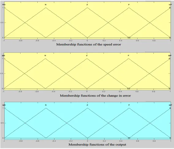
The four units are Fuzzification which convert the input non-fuzzy data to suitable linguistic variables. The second is fuzzy inference which make a decision for input according to a set of rules provided by the third unit which is rule base. The forth unit is defuzzification which convert the output fuzzy signal to a non-fuzzy output suitable to apply to a plant or to a system. [5] In this study the Mamdani type of fuzzy logic controller is used. Two inputs of FLC are speed error (e) and the change in speed error. By comparing the actual and reference speed the error is calculated. The major important thing in FLC is the if-then rules and the design of membership function for the input and output. [2] In this study the five membership functions are used for input and output which is shown in Fig. 4.Where MN is for more negative value, N is for Negative value, Z is for Zero value, P is for Positive value, and MP is for more positive value. In this study five membership functions are used, and of triangular shape for simplicity.
Now the rules will be defined. The 25 rules will be used in this study for controller simplicity and for its fast response. These rules are defined in Table 1.
Table 1. FLC Rule Table
Membership Functions
Change in Error
MN N Z P MP
E R R O R
MN MN MN N N Z
N MN N N Z P
Z N N Z P P
P N Z P P MP
MP Z P P MP MP
IV.SIMULATION &RESULTS
The Simulink is used for simulation of the system.
A. Simulation of DC Motor model with PI Controller
DC motor model with PI controller is simulated by Simulink as shown in Fig.5.
Fig. 5.Simulink diagram of DC Motor model controlled by PI controller
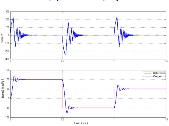
The circuit is simulated for a reference of 100 rad/s for up to 0.5 sec, -50 rad/s for 0.5 to 1 sec and 50 rad/s for 1 to 1.5 sec of time. The simulation result is shown in Fig.6.
Fig.6.Simulation result for PI controller
B. Simulation of DC Motor model with Fuzzy Logic Controller
DC motor with Fuzzy logic controller is simulated by Simulink as shown in Fig.7.
Fig.7.Simulink diagram of DC Motor model with Fuzzy Logic Controller
The circuit is also simulated here like for PI controller for a reference of 100 rad/s for up to 0.5 sec, -50 rad/s for 0.5 to 1 sec and 50 rad/s for 1 to 1.5 sec of time. The simulation result is shown in Fig.8.
Fig. 8.Simulation result for Fuzzy logic controller
C. Comparison of PI and Fuzzy Logic Controller
To decide which controller is better, the result of both controllers are combined in a graph and compared. The combined result is shown in Fig. 9.
Fig. 9.Combine result of PI & Fuzzy logic controller
V. CONCLUSION
Speed response characteristics of dc motor were obtained by Simulink. The result for PI controller have a settling time and have ripples. These defects are overcome by Fuzzy logic controller which have less settling time comparing to PI and also have less ripples. At starting time the FLC have good response than PI and for variation in load torque the PI controller have good performance but have problem of high starting overshoot and high settling time. As a result it is concluded that FLC has clearly better performance for providing rise time, overshoot and steady state error compare to PI controller. FLC also has more sensitivity to disturbance in load with respect to PI controller.
VI.APPENDIX
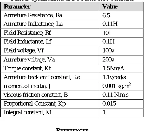
Table 2. Specifications of DC Motor & PI Controller
Parameter Value
Armature Resistance, Ra 6.5
Armature Inductance, La 0.11H Field Resistance, Rf 101
Field Inductance, Lf 0.1H
Field voltage, Vf 100v
Armature voltage, Va 200v Torque constant, Kt 1.5Nm/A Armature back emf constant, Ke 1.1v/rad/s moment of inertia, J 0.001 kg.m2 viscous friction constant, B 0.11 N.m.s Proportional Constant, Kp 0.015 Integral constant, Ki 1
REFERENCES
[1] A. B, Yildiz, (2012). Electrical equivalent circuit based modeling and analysis of direct current motors. International Journal of Electrical Power & Energy Systems, vol. 43, pp. 1043-1047.
[2] A. H. A. Hassan, D. Ishak and M. F. Z. Abidin, (2011). A comparative study of PI, fuzzy and hybrid PI-Fuzzy controller for speed control of brushless dc motor drive. Proceedings of Computer Applications and Industrial Electronics (ICCAIE), 2011 IEEE International Conference, place Penang, p. 189-194
[3] A. Ahmed, A. Chauhan, P. Sharma and Y. Mohan, (2013). Comparative Study of Speed Control of DC Motor Using PI, IP, and Fuzzy Controller. International Journal of Advanced Research in Computer and Communication Engineering, vol. 02, p. 2693-2697.
[4] K. A. Mohamad and W. I. Hameed, (2012). Speed Control of Separately Excited DC Motor Using Fuzzy Neural Model Reference Controller. International Journal of Instrumentation and Control Systems (IJICS), vol. 02.
[5] C. Chengaiah and K. Venkateswarlu, (2014). Comparative Study on Dc Motor Speed Control Using Various Controllers. International Journal of Advanced Research in Electrical, Electronics and Instrumentation Engineering, vol.03.
[6] H.A Smolleck, J. J. Wakileh, N. R. Prasad and S. Saneifard, (1998). Fuzzy-logic-based speed control of a shunt DC motor. Education, IEEE Transactions on, vol. 41, p. 159-164.
[7] H. M. Ertunc, S. Aydemir and S. Sezen, (2004). Fuzzy logic speed control of a DC motor. Proceedings of Power Electronics and Motion Control Conference, place Xi'an, p. 766-771.