© 2016, IRJET | Impact Factor value: 4.45 | ISO 9001:2008 Certified Journal | Page 1369
Mitigation of Voltage sag and Current Harmonics Using UPQC base PEMFC
ch.sumathi anjana rani
1,
Simhadri.swapna
2, k.srinu
31 PG Student, Department of EEE, BITS VIZAG , Visakhapatnam, Andhra Pradesh, India 2 Assistant Professor, Department of EEE, BITS VIZAG, Visakhapatnam, Andhra Pradesh, India
3 Assistant Professor, Department of EEE, Pydah College of Engineering, Visakhapatnam, Andhra Pradesh, India
---***---Abstract -
Power quality problem deals with multitude of individual types of power system disturbances. The presence of harmonics in power supply network poses a severe power quality problem that results in greater power losses in the distribution system, interference problems in communication systems and sometimes in operation failures of electronic equipment. This paper presents a three -phase UPQC base integration of proton exchange membrane fuel cell (PEMFC) . Which consists of a series compensator and a shunt compensator. Synchronous Reference Frame (SRF) theory is implemented for the generation of reference current signals for the controller. Matlab/Simulink is used for simulation. Simulation results confirms that the filter topology is capable of compensating the harmonics in load current, holding the voltage distortion within the stipulated limits as laid down by the IEEE 519 standard.Key Words: Shunt active power filter, series active power filter, voltage harmonics, current harmonics, nonlinear load.
1.INTRODUCTION
Power-electronics circuits are widely used in industrial equipment, such as frequency changers, motor-drive systems (AC voltage controller, chopper), etc. Such equipment presents nonlinear impedance to the utility, generating large harmonic currents and voltages withwell-known adverse effects, such as low power factor, low efficiency and destruction of other equipment. Also, some precision instruments and communication equipment will be interfered with the EMI.The effects of current harmonic distortion are poor utilization of distribution wiring and plant, increased power loss, high current flow in the neutral line and dangerous cable overheating. Voltage harmonic interrupts the proper operation of digital electronics mainly communications and process control, which needs sinusoidal supply voltage. Harmonic problem may result in mal-operation of protection equipment, which does not; itself draw harmonic currents from the supply.
Unified Power Quality Conditioner (UPQC) is a multi-function power conditioner that can be used to compensate various voltage disturbance of the power supply, to correct voltage fluctuation, and to prevent harmonic load current from entering the power system. It is a custom power device designed to mitigate the disturbances that affect the performance of sensitive and/or critical loads. UPQC has shunt and series compensation capabilities for (voltage and current) harmonics, reactive power, voltage disturbances (including sag, swell, flicker etc.), and power-flow control .Normally, a UPQC consists of two voltage-source inverters with a common dc link designed in single-phase, three-phase three-wire, or three- phase four-wire configurations. One inverter is controlled as a variable voltage source in the series compensator(APF or DVR).The other inverter is controlled as a variable current source in the shunt active power filter (APF). The series compensates for voltage supply disturbances (e.g. ,including harmonics, imbalances, and negative and zero sequence components, sag, swell, and flickers).The shunt APF converter compensates for load current distortions (e.g., caused by harmonics, imbalances) and reactive power, and perform the dc link voltage regulation.
© 2016, IRJET | Impact Factor value: 4.45 | ISO 9001:2008 Certified Journal | Page 1370 2. CONFIGURATION OF THE PROPOSED SYSTEM
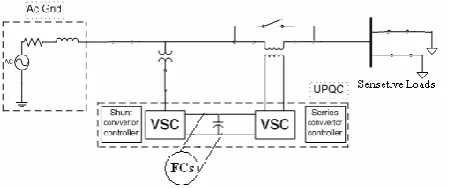
The proposed topology consists of a series and shunt active power filter. The active filter connected in series to a source acts as a harmonic isolator between the source and load whereas the shunt active filter is connected in parallel with a load and suppresses the harmonic current produced by the load.The PEMFC based UPQC compensates the voltage flaws and harmonics in the system and it is almost sustained to the reference value. The balanced and unbalanced voltage sag/swell and controller harmonics are mitigated with a closed loop controller
Fig -1: Combined operation of UPQC and PEMFCs
The proposed PEMFC based UPQC is analysed with the balanced and unbalanced voltage disturbances in MATLAB/Simulink
3. PROTON EXCHANGE MEMBRANE FUEL CELL
PEMFC uses a solid polymer electrolyte which has an exemplary behaviour in proton absorption an electron rejection. At the anode, hydrogen atoms split into electrons and positive ions in the presence of platinum catalyst . The positive ions travel through the membrane and are engrossed to the cathode, while the electrons ramble through the external load, generating a voltage across the load. Recombination of positive and negative ions takes place again with the help of the catalyst. The schematic diagram of PEMFC is taken from and is shown in fig. 2. The chemical reaction entangled in the PEMFC is given by the equ. (1), equ. (2) equ. (3).
H2 = 2H+ + 2e- (1) ½ O2 + 2 H+ + 2e- = H2O (2) H2 + ½ O2 = H2O (3)
The number of fuel cells are combined together to form a fuel cell stack. Fig. 2. Schematic diagram of PEMFC Due to the chemical reactions involved in the fuel cell, charged layers of opposite polarity are formed across the periphery of the porous cathode and the membrane. These layers are known as electrochemical double layer which behaves like a super-capacitor and stores electrical energy.
Fig -2: PEMFCs
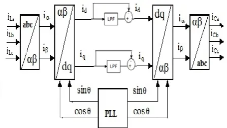
4.1 SRF-BASED CONTROLLER FOR CURRENT COMPENSATION
In this method the measured load currents are transformed into the rotating reference frame (d-q frame) that is synchronously rotating at the line voltage frequency using (4) and (5).The line frequency components of the load currents become DC quantities and the harmonic components are frequency shifted by ωt in the d-q reference frame.
4.1.1 Clark’s Transformation
It transforms sensed source current signal from a-b-c stationary to α-β stationary coordinate system by following equation
42 1 2 1 2 1
2 3 2
3 0
2 1 2 1 1
3 2
cc cb ca
o I
I I
[image:2.595.326.535.213.383.2] [image:2.595.49.274.302.396.2]© 2016, IRJET | Impact Factor value: 4.45 | ISO 9001:2008 Certified Journal | Page 1371 4.1.2 Park’s Transformation
Now this signal α-β is converted in d-q frame by using equation
5
cos
sin
sin
cos
I
I
t
t
t
t
I
I
q dA low pass filter in the d-q frame, with a cut-off at the line frequency can be used to extract the DC components as show in fig
4.2.2 Reverse Park’s Transformation (α-β to d-q)
6 cos sin sin cos q d I I t t t t I I Currents to transform them back to original frame, the inverse transformation from d-q to α-β frame, and then to a-b-c frame is carried out utilizing (6) and (7). 4.2.3Reverse Clark’s Transformation (d-q to a-b-c)
7 .. 2 1 2 3 2 1 2 1 2 3 2 1 2 1 0 1 3 2 I I I I I I c b aReference compensating currents(ica*,icb*,icc*) generated using current SRF controller which shown in fig 3
Fig 3 Reference compensating currents generated using SRF theory
4.2 SRF METHOD FOR VOLTAGE SAG SIGNAL GENERATION
In this method the measured voltages are transformed into the rotating reference frame (d-q frame) that is synchronously rotating at the line voltage frequency using (1) and (2).The line frequency components of the voltages become DC quantities and the harmonic components are frequency.
By using Clark’s and park’s the voltage signals va,vb,vc are converted to vd,vq (stationary quantity)equ(3)and equ(4) . This stationary quantity vd,vq is used to calculated volt1age sag signals. This voltage equation .the voltage vdq
varies with the grid voltages then the voltage sags can be detected from value of Vdq . Vdq is filtered by high pass filter (HPF) for 2ω or 100-Hz . As shown in figure The output of high pass filter is subtracted from vdq. .compared to low pass filter by using high pass filter we are getting better results mainly in current imbalances . The comparator output is a sag signal, which initiates a voltage sag compensation process when the voltage sag occurs.
Fig 4.Reference compensating sag voltages signal using modified method
5.HYSTERESIS CURRENT CONTROLLER
[image:3.595.320.552.455.515.2] [image:3.595.52.276.551.677.2]© 2016, IRJET | Impact Factor value: 4.45 | ISO 9001:2008 Certified Journal | Page 1372 The actual current with in this hysteresis
[image:4.595.313.558.53.218.2]band. The reference and actual current or voltage is compared with respect to hysteresis band which decides switching pulse of voltage source inverter
Figure 5.Hysteresis Controller
As the current crosses a set hysteresis band, the upper switch in the half-bridge is turned off and the lower switch is turned on (Figure 5). As the current exceeds the lower band limit, the upper switch is turned on and the lower switch is turned off. The switching frequency depends on how fast the current changes from upper limit to lower limit and vice versa. This, in turn depends on voltage vd and load inductance.
[image:4.595.62.265.169.244.2]6.SIMULATION RESULTS
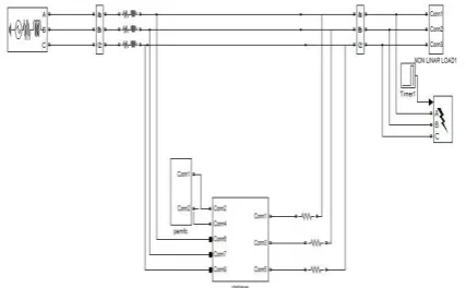
Fig 6.1 simulation model without compensator
Fig 6.2 simulation model with upqc with PEMFC
Fig 6.3 voltages sag in line without compensator
Fig 6.4 voltages sag in line with compensator
Fig6.5 current harmonics in line without compensator
[image:4.595.45.278.437.524.2]Figure 6.6 FFT analysis for current wave without compensation
[image:4.595.55.269.581.713.2] [image:4.595.319.547.612.688.2]© 2016, IRJET | Impact Factor value: 4.45 | ISO 9001:2008 Certified Journal | Page 1373 Figure 6.8 Current in line with compensator
Figure 6.9 FFT Analysis for current wave with compensator
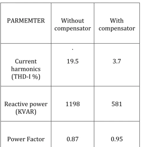
6.1: Results
PARMEMTER Without compensator
With compensator
Current harmonics (THD-I %)
.
19.5 3.7
Reactive power (KVAR)
1198 581
Power Factor 0.87 0.95
Table 1 comparison of without compensation and with compensation
7.1 CONCLUSION
The proposed PEMFC based UPQC is capable of reducing the voltage sag and current harmonics. After compensation of current harmonics, the source current is Sinusoidal waveform, having THD 3.7%. It compensates harmonics present in the power system
and the percentage of current thd values is reduced and reactive power is decreased and power factor is improved.
8. REFERENCES
[1] Bajpai R.S., Gupta R., “Series compensation to mitigate harmonics and voltage sags/swells in distributed generation based on symmetrical components estimation”, In IEEE conference on Industrial electronics (ISIE); 27-30 june 2011 pp: 1639-1644 .
[2] Omar R, Rahim NA, “Voltage unbalanced compensation using dynamic voltage restorer based on supercapacitor”, IntElectrJ Power Energy System
2012;43(1) pp:573–81.
[3] Jowder FAL, “Design and analysis of dynamic voltage restorer for deep voltage sag and harmonic compensation”, IET Generation, Transmission and Distribution. 2009;3(6) pp:547–60.
[4] Palanisamy K, Kothari DP, Mahesh K Mishra, Meikandashivam S, Jacob RaglendI, “Effective utilization of unified power quality conditioner for interconnecting PV modules with grid using power angle control method”, Int J Electric Power Energy System 2013;48:131-8.
[5] Rajakumar P, saravanakumar R, Thirumalaivasan R, “Power quality enhancement using photovoltaic based dynamic voltage restorer”, In IEEE conference on Advances inElectrical Engineering (ICAEE); 9-11 jan pp:1-4.
[image:5.595.35.273.395.643.2]