CDMA BASED SECURITY FOR WARM-HOLE ATTACKS IN
UNDERWATER WIRELESS SENSOR NETWORK SYSTEM
1K.DURGA DEVI Member IEEE, 2M.MENAKA
1
Assistant Professor, Department of Computer Science & Engineering C.Abdul Hakeem College of Engineering and Technology
Melvisharam - 632509, TamilNadu, India.
2
Assistant Professor, Department of Computer Science & Engineering Kingston Engineering College
Chittoor Main Road, Vellore 59, TamilNadu, India.
E-mail: [email protected] , [email protected] ,
2
ABSTRACT
Regular activity of the human is being extended to marine and sub-marine regions. Invention of war activity and marine research on minerals and bio-diversity is leading to install wireless sensor devices in deep underwater system. The underwater sensors and network areas are applied through a number of applications like research, water games, self-defense against enmity, finding of minerals and study of the effect of soil erosion, bio-diversity, and greenhouse effect. Marine weather is having a strong impact on the transmission system. Marine weather imposes highly corrosion, multipath fading, high delay, limiting bandwidth, multi-path fading on the transmission system. Worm-hole is one of the multi paths fading error in underwater sensor technology. A wormhole is caused by the mirror image effect of transmission system from one device to another device. Wormhole causing serious problem like fading of important data, adverse effect on the neighbor devices present in underwater system, illegal data transmission and using valuable bandwidth. To avoid the warm - hole effect on under water network system this method proposes a CDMA based transmission which is having a numbering system for every device present in the network, every node is having a controller which can detect it through calculation method. This technique is an efficient error detecting technique without any overload of extra hardware device and complex protocol.
Keywords:Underwater Sensors, Worm-Hole, CDMA Technology, And Authentication Check
1. INTRODUCTION
The Earth is a water planet. Around 70% of the surface of earth is covered by water. This is largely unexplored area and recently it has fascinated humans to explore it [1]. The presence of human culture is on land areas only. Long range transmission is increasing on its dependability on day to day life. Wireless communication satellite is one of the solutions for long range data transmission. Communication through wireless satellite is costly as well as inefficient in huge data transmission case. Physical structure of material present in current scenario is unable to show zero error. Long range transmission is mandatory as continents are divided through the oceans. A number of wireless sensors are present in the sea level. Underwater sensors were having a lot of problems at the time of data transmission. Generally
the errors are link failure, flow of data in any route, unwanted delay in transmission, bandwidth loss due to the presence of high wave energy. To avoid this kind of problem networks are deploying a number of devices like routers and repeaters. But in case of wireless sensors and data transmission one more problem is coming named worm hole which is due to mirror image of nodes present in the network.
1.1.Architecture
communications with the deployed UW-sinks. Some of the architectures supporting underwater sensor networks are static two-dimensional under water acoustic sensor networks (UW-ASNs), static three dimensional underwater acoustic. Sensor networks and three dimensional networks of autonomous underwater vehicles are given in [12]. Static two-dimensional UW-ASNs are constituted by sensor nodes that are anchored to the bottom of the ocean. Static three-dimensional UW-ASNs include networks of sensors and are used for surveillance applications or monitoring of ocean phenomena (ocean bio–geochemical processes,
water streams, pollution). Three-dimensional
networks of autonomous underwater vehicles (AUVs) networks include fixed portions composed of anchored sensors and mobile portions constituted by autonomous vehicles. [2]
1.2 Applications
Natural or man-made disasters that took place over the last few years have aroused significant interest in monitoring oceanic environments for scientific, environmental, commercial, safety, homeland security and military needs. The shipbuilding and offshore engineering industries are also increasingly interested in technologies like wireless sensor. [1] [2] [5] Wireless underwater networking is the enabling technology for ocean
applications. Long term non-time critical
application concerned with long term non-time critical applications. Networks of sensors and
underwater vehicles can perform synoptic,
cooperative adaptive sampling of the coastal ocean environment. Underwater acoustic sensor networks (UW-ASNs) can perform pollution monitoring (chemical, biological and nuclear) [7]. Monitoring of ocean currents and winds, improved weather forecast, detecting climate change, under-standing and predicting the effect of human activities on marine ecosystems, biological monitoring such as tracking of fishes or micro-organisms, are other applications. Underwater sensor networks help to detect underwater oil fields or reservoirs, determine routes for laying undersea cables, and assist in the
exploration for valuable minerals. Another
application is supporting groups of underwater
autonomous robots. Applications include
coordinating adaptive sensing of chemical leaks or biological phenomena (for example, oil leaks or phytoplankton concentrations), and also equipment
monitoring applications. The simultaneous
operation of multiple underwater acoustic vehicles with acoustic and optical sensors can be used to perform rapid environmental assessment and detect
mine-like objects [8]. The self-reconfigurable UWSN tolerates more faults than the existing
tethered solution.Sensor networks measure seismic
activity from remote locations. They can provide tsunami warnings to coastal area and study the effects of submarine earthquakes (seaquakes). Sensors can be used to identify hazards on the seabed, locate dangerous rocks or shoals in shallow waters, mooring positions, submerged wrecks, and to perform bathymetry profiling. Autonomous underwater Vehicles (AUVs) and fixed underwater sensors can collaboratively monitor areas for surveillance.
1.3. Issues
Major challenges encountered in the design of underwater acoustic networks are as follows [11] [12].
1. The available bandwidth is severely
limited.
2. The underwater channel is impaired
because of multi-path and fading.
3. Propagation delay in underwater is five
orders of magnitude higher than in Radio Frequency (RF) terrestrial channels, and variable.
4. High bit error rates and temporary losses
of connectivity (shadow zones) can be experienced.
5. Underwater sensors are characterized by
high cost because of extra protective sheaths needed for sensors and also relatively small numbers of suppliers (i.e., not much economy of scale) are available.
6. Battery power is limited and usually
batteries cannot be recharged as solar energy cannot be exploited.
7. Underwater sensors are more prone to
failures because of fouling and corrosion. The real challenges came into play at the time of Deploying and retrieving and using the sensors is labor intensive; Collecting the data is subject to very long delays. The manual aspects of using the sensors lead to error. The spatial scope of data collection with individual sensor is limited; Individual sensors are unable to perform operations that require cooperation, such as tracking relative movement and locating events. [3]
1.4. Differences between Wireless Sensor Network (WSN) and UWSN
(large delay, long distance of communication) of network, the communication is relied on physical means like acoustic sounds to transmit the signal. Traditional RF networks do not work efficiently in underwater networks. Due to distinct network dynamics, existing communication protocols for terrestrial networks are not suitable for the underwater environment. Low bandwidth and large latency result in long end to end delays. Terrestrial networks are becoming inexpensive due to advancement in technology but underwater sensors are still expensive devices. This is due to the extra protection required for underwater environment and more complex transceivers needed. Terrestrial networks are densely deployed, whereas in underwater networks the deployment is sparser due to the challenges involved in deployment and also the cost involved in deployment. In terrestrial networks, due to higher distance of communication, type of media being used for communication, signal processing techniques involved at the transceivers, the power required is more and more complex as compared to terrestrial sensor network. In case of terrestrial network nodes mobility can be predicted whereas in the underwater networks prediction of mobility of the node is difficult, because of the density and flow variation of the water. Underwater sensors need to have a large memory compared to terrestrial sensors as the underwater channel is intermittent. Readings taken from terrestrial networks with sensors are often correlated but this is not the case in underwater networks as the distance is more among the sensors.
To avoid above mention worm hole problem this method purposes a CDMA based calculation for worm hole detection in under water wireless sensor network. The basic thing of techniques is selected as a transmission system network system. Every node in the network system has its identity as some number. Some mathematical calculation as well as some authentication checking table present at the nodes help to determine about the wormhole attack and identify the exact location of the attack.
This method gives some introduction about the wormhole with the architecture of the underwater wireless sensor network. Then this method provides some applications and errors relates to under water sensor network. This proposal proceeds to describe some earlier work done in the literature part, which is present in section-2. Then the proposal is described in an elaborated manner in section-3. Finally this paper gives the result of CDMA based security for wormhole detection in underwater sensors through an analysis and conclusion.
2 LITERATURE REVIEW
2.1 Visualization Of Wormholes In Underwater Sensor Networks
The author [1] focus on the detection of wormhole attacks. The sensors use a shared acoustic channel to send information in underwater environments; the malicious nodes can eavesdrop on the packets, tunnel them to another location in the network, and retransmit them. This attack generates a false scenario that the original sender is in the neighborhood of the remote location. The author proposes an algorithm called Dis-VoW. Using the distances measured by the propagation delay of acoustic signals, every sensor reconstructs the local network topology using multi-dimensional scaling. Dis-VoW detects wormholes by visualizing the distortions in edge lengths and angles among neighboring sensors. A normalized variable wormhole indicator is defined based on these distortions to identify fake neighbor connections
Dis-VoW can detect most of the fake neighbor connections without introducing many false positive alarms, even when there are multiple wormholes in the network. Since Dis-VoW reconstructs networks and detects wormholes in a distributed manner, the scheme will introduce a limited amount of computation and storage overhead to the sensors.
Extensions to Dis-VoW are under construction. The author plans to apply the distributed detection mechanism to land-based sensor networks in 3D environments. The author investigates the joint impacts of multiple wormholes on localized network reconstruction. The research leads to a more accurate, robust, and efficient solution to
defend against wormhole attacks.
2.2 Security In Wireless Sensor Networks
security layers, for example; if a sensor is somehow captured or jammed in the physical layer, the security for the overall network breaks despite the fact that, there are some efficient security mechanisms working in other layers.
A holistic approach [8] aims at improving the performance of wireless sensor networks with respect to security, longevity and connectivity under changing environmental conditions. The holistic approach of security concerns about involving all the layers for ensuring the overall security in a network. By building security layers as in the holistic approach, protection established for the overall network.
2.3 A Query Result Merging Scheme For Providing Energy Efficiency In Underwater Sensor Networks
[10] The authors suggest a multiple query result merging scheme solution for problems in underwater sensor network data transmissions. The proposed framework is a technique for providing data on-demand from an underwater sensor network to multiple-users simultaneously in an
energy-efficient manner. “A Query Result Merging
Scheme for Providing Energy Efficiency in Underwater Sensor Networks scheme” doesn’t require processing capabilities greater than those of a conventional ubiquitous sensor node. The proposed query models are simple and don’t store data history, thus consuming only a limited space of memory. The query condition merging process in the QRP is also a succession of reasonably arduous logical processes manageable with microprocessors of regular capacity, so the proposed query management scheme asks for no more than the processing capability of a regular sensor node The current technology is too vulnerable to underwater environments for practical time synchronization to happen. Developing a method for effectively distributing queries or query sets to the target nodes can significantly enhance the performance of frameworks. Increasing query functionality by adding other relational operations (the “join” operation, for example) would also be meaningful.
3. PROBLEM IDENTIFICATION AND PROPOSED SCHEME
3.1 Problem Definition
Underwater sensor network is coming under major network erosion. One of the main problems
is worm-hole. Worm-hole is caused by the mirror image concept. As under water has high wave energy alternates the flow of the data under high wave energy. The existing detection methods present on the land surface are unable to detect worm hole present in the network. Some existing technology present in [1] is unable to detect the black hole in a real scenario. It is limited to two dimensional surfaces only. Underwater surfaces are not playing in nature. So the demand of adoptions 3D network is mandatory in deep under-water network. The proposal given in [6] extends to different layers of the network. This proposal needs
a complicated synchronization technology.
Working in different layer is leading more delay while delay is a major area to focus on the security of under water is delayed. Although the proposal given through multi query result merging scheme in [10] is able to put reliability in under water wireless sensor technology, it is using the bandwidth just to detect the right data packet. Availability of bandwidth in underwater system is among one of the major problems. Pressure on bandwidth leads to low rate data transmission.
Proposed method
Before going to the bottom part of the problem of worm-hole solution method, here this method is describing a general architecture of underwater sensor network. Underwater networks are in random arrangement. The detail arrangement is given in figure-1. Here the network consists of several numbers of nodes. Each node can communicate with each other node. The nodes are identified through a unique identification number
(Uid). This is equal to the MAC (medium access
control) in the device. The Uid of all devices
installed at the time of initialization of network.
Here the Uid is CDMA code of the specific node
To avoid the above problem, this method follows a CDMA based calculation method for worm hole detection in the underwater network system. Here below a an architectural diagram of this solution is given. The architectural diagram divides the under water network in to three sets of logical area. First one is sender, second one is intermediate nodes, third one is receiver nodes. All these three sets are related with each other through the protocol, which is used to avoid worm hole.
(Figure-2 Showing The Architectural Diagram For
Worm Detection)
For eliminating unwanted data packets using CDMA technology this method assumes some points. The nodes are communicating with each other using CDMA technology. In CDMA technology all the nodes are given a unique code [15] [16] [17]. All the nodes in a cluster those are communicating with each other should have the authnication of getting the data from a specific number of nodes which cannot be changed automatically. There is a predetermined index table is present at the receiver nodes. The set of authenticated sender Is present in the index table.
3.2 Generation Of Data Packet
Data is generated at the sender node. The data packet is described below.
(Figure-3: Shows The Data Packet Structure)
In the above data packet header carries the receiver's address and sender node’s address. Counter function (CF) is the function which is
related destination as the source. This was decided at the time of initialization of the network for the static field present at the destination node. At the time of sending the data packet the sender added a special field starting with 0. CDMA codes are the codes given to every node, which are used for network linking and identification. Here CDMA codes are taken as numeric values. CDMA values are fixed at the during the data packet transmission in a network. At the sender CDMA code for prior node is zero. Summation of CDMA from prior node to current node is CDMA code of the sender. The data packet carries the useful data to be transferred or original information in another field of the data packet. So the data packet is
(Figure-4: shows the data packet structure)
3.3 Regeneration Of Datapacket At Inter Mediate Node
When a node receives a data packet it first checks the receivers address. If the receiver is not matching with its own id (which is the CDMA
number given to it) of intermediate it makes an
alteration in the data packet. At the intermediate node the data packet is changed. The changed data packet carries the fields of the header and data as same the received data packet. The fields like CDMA code of previous node and summation of CDMA codes are changed. The summation of CDMA code is given by summation of CDMA code of previous node to the current node. The counter function is increased by 1 at each intermediate transmission. The data packet will be
(Figure-5: Shows The Data Packet Structure)
The algorithm of generation of the data packet is given by
At sender
Int [] generateDatapacket ()
{
Private Int CDMA=CDMA code; //
prefixed
Void generateDATA (); // data generation module
Int finalDatapacket [] =null; //initialization phase
Constant Int header= header; // previously determined
finalDatapacket=finalDatapacket. Concate (header);
finalDatapacket=finalDatapacket. Concate (counterfunction);
finalDatapacket=finalDatapacket. Concate (data);
finalDatapacket=finalDatapacket. Concate (summation [0]);
Return finalDatapcket [];
}
At intermediate node-
1. Receives data packet (int dataPacket []);
2. Check address field (int dataPacket [])
{
If (adress=own id)
{
Call
Destination (int dataPacket []);
}
Else
Call intermediate node (int dataPacket []);
}
3.4 Error checking method present at the destination
This paper focuses error checking method at destination node. The destination node has data table which carries some static values as well as some dynamic values. Static values was determined at the time of initialization of the network. In the index table the sender nodes address, counter function and a predetermined summation of CDMA values is fixed or static. While the received counter function and summation of CDMA codes will be dynamic. These two field will be entered in the index table at reception of each data packet. Counter function and sending node confuguration can be different. The table is given below
Counter function (value of
c)
Sender node
Summation of CDMA
code
Received counter function
Received summation
of CDMA values
Status (accepted/rejected)
……….. …….. ………… ……… …………. ……….
………….. ………. ……. ……….. …….. ……..
(Figure-5 Showing The Worm Hole Detection Table Present At Destination Node)
The destination node sets the status according to the results from the index table present at the destination node. Here counter function and summation of CDMA is checked according to the
sender node’s Uid values. The worm hole is detected
the following combinations.
Sender node&& (static summation of CDMA code. Equals to (received summation of CDMA codes)) && (static counter function. Equals to (received counter function))
If the above value comes negative then the transmission is detected as a worm-hole attacked.
Worm-hole is detected from the following scenarios
Having same senders address
• Same static counter function and received
counter function but different static
summation of CDMA codes and received summation of CDMA codes.
• Same summation of CDMA codes in
received field and received field but different values in static counter function and received counter function.
• Different values of counter functions at
received field and static field and different values at summation of CDMA codes at static field and received field.
Procedure for worm-hole detection
1. Create an index table at the time of
and summation of CDMA codes present with respect to the senders address.
2. When a data packet is received by the
destination or end node it first gets the counter function, summation of CDMA codes and sender’s address.
3. Counter function and summation of
CDMA code is stored at their respective place.
4. Through comparison method worm-hole is
detected which is described above.
Steps to be followed
1. All the devices present at under water
sensors are modified to be capable of CDMA technology transmission.
2. The sender node generates the data packet
as given in section 3.1.
3. Then the data packet is sent through the
long range data packet transmission system.
4. When a node gets a data packet it first
checks whether the current node is intermediate node or destination or end node.
5. If it is an intermediate node then the does
necessary modification given at section-3.2 and regenerates the data packet. After generating the data packet the intermediate node forwards the data packet towards the destination.
6. The destination node is having an index
table with them.
7. The destination or the end node accepts or
rejects the data packet going through the process of authentication given in section 3.3.
8. If the data packet is rejected, then the
destination node issues worm-hole attack signal.
Example
To better understand this paper is considering the figure-1 condition. In this case if a data packet is required to travel from 1 to 12 then the packet should go through 2, 3, and 4,5,11. In this case the data packet travels through only 2 and 11. Using CDMA technology we can create the different nodes identification. Suppose the CDMA code of node 2 is 121 and node 1 is 119and 3 is 100 and 5 is 110 and 8 is 112 and 11 is 115. This paper introduced a count function at node 1. In the count
function there is a variable c which is initialized to 0. Suppose the count function adds 1 each time when it passes through a node (we can use different type of complex function for more security). The index table which is pre-determined and stored at 12 is
Counter function (value of c)
Sender node
Summation of CDMA
code
4 2 558
5 1 777
If node 12 gets packed from node1 where the counter function is 5 and summation of CDMA is 777 then the packet at 12 is accepted. If the packet is traveled through only 2 and 11 then the counter function is 2 and summation of CDMA code is 236. Looking into the table node 12 without having a match in the index will simply discard the packet. Before going to the node 12 the wormhole can be detected at node 11. It stops further processing of data.
4. SIMULATION RESULTS
4.1 Simulation Parameters
The proposed CDMA Based Security
(SecCDMA) for Warm-hole Attacks in UWSN is simulated using NS2 [18]. In this simulation, the channel capacity of mobile hosts is set to the value of 2 Mbps.
In the simulation, the number of nodes is 50. The mobile nodes move in a 1000 meter x 10 meter square region for 50 seconds simulation time. In our simulation, the number of attacker are varied as 5,10,15,20 and 25.
[image:7.595.318.496.210.276.2]The simulation settings and parameters are summarized in table 1.
Table 1 Simulation Parameters
No. of Nodes 50
Area 1000 X 10
MAC UnderwaterMac
Simulation
Time 50 sec
Channel UnderwaterChannel
Range 100m
Attackers 5,10,15,20 and 25
Mac
[image:7.595.329.502.612.746.2]Routing Protocol
Vector based Forward Antenna
Type Omni Antenna
Initial
Energy 10000 J
Transmission
power 2.0
Receiving
Power 0.75
Idle Power 0.008
Filters Gradient Filter
Frequency 25Khz
4.2 Performance Parameters
We compare the SecCDMA with the Normal Attack scenario. We evaluate performance of the SecCDMA mainly according to the following parameters.
Average end-to-end delay: The end-to-end-delay is averaged over all surviving data packets from the sources to the destinations.
Average Packet Delivery Ratio: It is the ratio of the number of packets received successfully and the total number of packets transmitted.
Energy: It is the amount of energy consumed for the data transmission
.The simulation results are presented in the next section.
4.3 Simulation Results
A. Based on Attackers
In our experiment we vary the number of attackers as 5, 10, 15, 20 and 25.
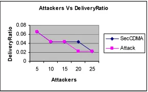
Attackers Vs DeliveryRatio
0 0.02 0.04 0.06 0.08
5 10 15 20 25
Attackers
D
e
liv
e
ry
R
a
ti
o
[image:8.595.87.512.73.341.2]SecCDMA Attack
Fig 6: Attackers Vs Packet Delivery Ratio
Attackers Vs Delay
0 5 10 15
5 10 15 20 25
Attackers
D
e
la
y
(S
e
c
)
SecCDMA Attack
Fig 7: Attackers Vs Delay
Attackers Vs EnergyConsum ption
0 500 1000 1500
5 10 15 20 25
Attackers
E
n
e
rg
y
(J
)
[image:8.595.86.284.105.285.2]SecCDMA Attack
Fig 8: Attackers Vs Energy
From figure 6, we can see that the delivery ratio of our proposed SecCDMA is higher than the existing Attack scenario.
From figure 7, we can see that the delay of our proposed SecCDMA is less than the existing Attack method.
From figure 8, we can see that the energy consumption of our proposed SecCDMA is less than the existing Attack scenario.
5. CONCLUSION
Using the above described technology of CDMA based security for worm-hole detection in underwater wireless sensor networks. It is easy to avoid the unwanted packets at the receiver node. So it decreases the network traffic. As it is not considering the amount of packets; it will sustain against large amounts of wormhole attacks. No need of adding more number of hardware at the nodes. The counter function carries a simple algorithm. This method does not provide any solution in the cost of bandwidth and delay. This method can be applied on three dimensional areas.
[image:8.595.117.262.582.672.2]REFERENCES
[1] Weichao Wang, Jiejun Kong, Bharat Bhargava, Mario Gerla “Visualisation of wormholes in
underwater sensornetworks: a distributed
approach”2008.
[2] Manjula.R.B, Sunilkumar S. Manvi “Issues in Underwater Acoustic Sensor Networks”, 2011. [3] Carrick Detweiller Iuliu Vasilescu Daniela Rus,
“An Under-water Sensor Network with Dual Communications, Sensing, and Mobility” , 2007.
[4] Javier Lopez, Rodrigo Roman, and Cristina
Alcaraz,” Analysis of Security Threats,
Requirements, Technologies and Standards in Wireless Sensor Networks”, 2010
[5] Vivekanand Jha1 ,Preeti Gupta2 and Urvashi Ahuja” QoS Issues In Underwater Sensor Networks”2006
[6] Al-Sakib Khan Pathan , Hyung-Woo Lee, Choong Seon Hong “Security in Wireless Sensor Networks: Issues and Challenges” 2007 [7] Gunilla Burrowes and Jamil Y. Khan
“Short-Range Underwater Acoustic
CommunicationNetworks”2011
[8] Ra´ul Palacios Trujillo “Interference
Cancellation and Network Coding for
Underwater Communication Systems”2010. [9] Petar Djukic, Yifeng Zhou, Myl`ene Toulgoat
“Localization for Electromagnetic Radio
Underwater Sensor Networks”, 2011
[10] Yunsung Kim 1 and Soo-Hyun Park “A Query Result Merging Scheme for Providing Energy Efficiency in Underwater Sensor Networks” 2011. www.mdpi.com/journal/sensors
[11] Jun-Hong Cui1, Jiejun Kong2, Mario Gerla2, Shengli Zhou3” Challenges: Building Scalable Mobile Underwater Wireless Sensor Networks for Aquatic Applications”2006.
[12] Ian F. Akyildiz *, Dario Pompili, Tommaso Melodia” Underwater acoustic sensor networks: research challenges”2005
[13] Mohammad Ali Shamalizadeh, Shahaboddin Shamshirband, 1 2 3Mohsen Amiri, 4Samiria
Kalantari “Security in Wireless Sensor
Networks Based On Service-Oriented
Architecture”
[14] Dimple Juneja, Neha Arora “ An Ant Based Framework for Preventing DDoS Attack in
Wireless Sensor Networks”, 2010
[15] YU-TENG CHANG, CHENG-I HOU,” A STUDY ON CELLULAR CDMA-BASED FOR NEW GENERATION MOBILE RADIO SYSTEM”, Journal of Theoretical and Applied Information Technology
[16] ramjee prasad, delft university of technology tero ojanperä, nokia telecommunications,” an overview of CDMA evolution Towardwideband
CDMA”,ieee, Communications,
www.comsoc.org/pubs/surveys
[17] By Enrico Zanoio and Steve Urvik,” White Paper: CDMA Network Technologies: A Decade of Advances and Challenges” Monitoring
and Protocol Test, Tektronix, Inc. [18] Network Simulator: