GRID INTERFACE OF A PMSG BASED WIND ENERGY
CONVERSION SYSTEM WITH POWER QUALITY
IMPROVEMENT FEATURES
1R.KARTHICK, 2S.MANOHARAN, 3S.RAJKUMAR 1
Asstt Prof. and Research Scholar, Department of Electrical Engineering, SNS College of Technology, Coimbatore, India.
2
Prof., Department of Electrical Engineering, Karpagam College of Engineering, Coimbatore, India.
3
PG Scholar, SNS College of Technology, Coimbatore, India
E-mail: [email protected], [email protected], [email protected]
ABSTRACT
Renewable Energy Sources are nowadays rapidly growing popularity at the distribution level which employs power electronic converters, which ensures reliable operation to customers. Among the RES, wind energy is now firmly established as a mature technology for electricity generation. This paper discusses the role of ac/dc/ac power converter for grid interface of wind energy. The generator side converter incorporates the maximum power point tracking algorithm to extract maximum energy from wind turbine system. The grid side converter plays a dual role of interfacing the wind energy to grid as well as to supply reactive power as demanded by the non-linear load connected at the PCC. A simple model of the proposed system is developed and simulated in MATLAB environment. The effectiveness of the system is validated through extensive simulation results.
Keywords:Permanent Magnet Synchronous Generator (PMSG), Maximum Power Point Tracking (MPPT), Dc-Dc Converter, Grid Side Inverter, Power Quality.
1. INTRODUCTION
In recent years, due to the fast depleting conventional energy resources and the concerns over climatic changes, the renewable energy sources are gaining popularity around the globe. Among the available renewable energy sources, the wind energy and the solar energy are the most mature technologies for power generation. The main advantage of renewable energy is that it is clean and inexhaustible. But the major disadvantage is that it is interim in nature and depends on seasonal pattern [1]. Therefore it is difficult to operate the power system only with renewable energy due to their characteristic difference and their uncertainty of availability. The potential of renewable energy sources is fully extracted by interfacing them to the existing grid.
Power electronics, being the technology of efficiently converting electric power, plays a vital role in integration of renewable energy sources into the electric grid to achieve high efficiency and performance in power system [2]. By doing so, the system has to supply power to the grid and also support the grid during any kind of fault. Moreover voltage variations, flickers, harmonic generation
and load unbalance are the important power quality problems that need an immediate attention. The conventional WECS uses a Statcom as voltage compensators at PCC. This results in the overall cost of the system. The main idea behind this work is to extract maximum power from the wind and fully utilize the inverter, not only to interconnect the power to the grid but also to address the power quality problems. Almost all the commercial inverters for hybrid systems inject only active power to grid. It is possible to incorporate the power quality capabilities for reactive power compensation and eliminate the load current harmonics thereby maintaining the grid current almost sinusoidal.
supplying reactive power as demanded by the non-linear loads at PCC. The simulation results show that maximum power is harvested and the inverter injects real power to the grid as well as mitigate the power quality issues.
The paper is organised as follows: the wind energy conversion system is discussed in section 2. The control and MPPT for WECS is discussed in section 3. The inverter side control along with dc link control is discussed in section4. Section 5 gives the simulation results on MATLAB platform. The conclusion is discussed in section 6.
2. SYSTEM DESCRIPTION
2.1 Wind Energy Conversion System
The wind generator system using Permanent Magnet Synchronous Generator is shown in fig.1. The kinetic energy produced by the wind turbine is the most desirable type of energy which is converted into electrical power which can be stored in batteries or linked to a utility power grid [5]. The useful power available from wind is given by
(1) where ‘ρ’ is the air density which depends on air pressure and moisture, ‘A’ is the circular swept area, ‘v’ is the wind velocity. The power coefficient Cp is usually given as a function of the tip speed
ratio λ’ and the blade pitch angle ‘β’.
An important parameter of wind of wind rotor is the tip speed ratio λ which is the ratio of the circumferential velocity of the blade tips and the wind speed.
(2)
where ‘D’ is the outer turbine diameter and ‘Ω’ is the angular rotor speed. The power coefficient, denoting the power extraction efficiency is given by,
(3) where
The power from the wind is maximized when the power coefficient is at its maximum. This occurs at a defined value of the tip speed ratio λopt. Hence for
each wind speed there is an optimum rotor speed where maximum power is extracted from the wind.
Thus by controlling the rotor speed, the power output of turbine is controlled.
2.2 Electrical Generator:
Recently, the commercial trend of wind power generation is in using variable speed wind turbine driving a Permanent Magnet Synchronous Generator (PMSG). PMSG is considered in many research articles, a good option to be used in WECS due to its self-excitation property, which allows operation at high power factor and efficiency. The salient pole of PMSG operates at low speed and thus the gearbox can be removed. This is a big advantage of PMSG based WECS as the gearbox is a sensitive device in wind power systems. The mathematical model of a PMSG is similar to that of a wound rotor synchronous machine and is expressed in the rotor reference frame (dq frame) [3].
(4)
(5) The total input power into the machine is given by,
(6)
Neglecting the zero sequence quantities, the mathematical output power Pout is given by,
(7)
Neglecting the zero sequence quantities, the mathematical output power Pout is given by,
(8) where ‘λm’ is magnetic flux, ‘Ld’ is direct axis
inductance, ‘Lq’ is quadrature axis inductance.
characteristics of a typical turbine is shown in Fig2, from which we understand that the maximum power point is obtained when,
(9)
The generated electric power is given by,
(10)
Vdc is proportional to the generator phase voltage
Va.
Maximum power is at
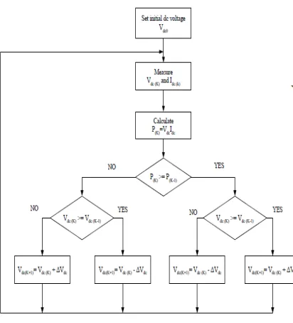
The maximum power is tracked by searching the rectified dc power rather than environmental conditions. In order to search for maximum power at any wind speed, four conditions must be met. The maximum power searching process is initiated by setting an arbitrary dc side voltage reference Vref. The controller then measures both the dc side
current and voltage, and calculates the initial electric power
Po= VdcIdc. Next, the reference voltage Vref is
increased by ΔVdc so that.
(11)
Fig.1. Grid connected WECS with MPPT controller
The flow chart for the MPPT is shown in fig 3. If P(k) is bigger than P(k - 1), the maximum power point has not been reached therefore, the voltage reference needs to be increased by ΔVdc and the dc
power needs to be compared. This process will repeat until maximum power is reached. And if P(k) is less than P(k - 1), the dc voltage reference is then decreased by ΔVdc. In order to search for
maximum power at any wind speed three conditions must be met [7].
(1). If P(k)≥P(k-1) and Vdc(k)≥Vdc(k-1), the dc side voltage reference need to be increased by ΔVdc.
This condition is met when the turbine operates on the low speed side of the power curve as shown if Fig.4.
(2). If P(k)≥P(k-1) and Vdc(k)˂Vdc(k-1), the wind turbine is being operated in the high speed side and the dc reference voltage needs to be decreased by
ΔVdc.
(3). If P(k)≥P(k-1) and Vdc(k)≥Vdc(k-1), the dc side voltage reference need to be increased by ΔVdc.
Fig. 2. Wind Turbine Characteristics
Fig.4. MPPT Tracking process
3. POWER ELECTRONIC INTERFACE
3.1 DC-DC converter controller
The AC output voltage from the wind generator is rectified using a three phase bridge rectifier. The DC output is then fed to a DC-DC converter whose main purpose is to increase the variable dc voltage from the diode rectifier to a constant DC voltage which is fed into the inverter. The circuit for the boost converter is shown in the Fig 5, which works
by storing enough energy in the inductor so that the output is the desired voltage throughout the switching action. When the switch is closed, the energy is stored in the inductor. Then the energy is transferred to the capacitor when the switch is open [6]-[7]. The switch is controlled by a PWM signal generated by the MPPT controller. The duty cycle of the PWM signal determines the output voltage,
(12)
[image:4.595.293.518.339.472.2]where Vi is the input voltage, Vo is the output voltage and D is the duty ratio.
Fig.5. DC-DC Boost Converter
The DC-DC converter uses a simple feedback controller. The DC voltage reference is compared with the actual DC voltage, and the error signal is fed to a PI controller. The output signal is compared with a triangular waveform to generate the pulse which will turn ON or OFF the MOSFET switch.
4. GRID SIDE INVERTER CONTROLLER
[image:4.595.85.291.370.597.2]Fig.6. Grid Side Inverter Control Structure
(13)
(14)
Since the three-phase grid voltages are with constant amplitude and with constant frequency, Vd
and Vq are constant. In a balanced three-phase
system, active and reactive powers in the d-q reference frame can be expressed as:
(15)
(16)
Since the rotating reference frame is aligned with the d-axis, Vq is zero, the above equation can be
expressed as,
(17)
(18)
The power transferred via the DC link should be equal to the power fed into the grid. Therefore,
(19)
From the above equation, it can be seen that the active power control can be achieved by controlling direct axis current id.
The reactive power is also implemented in the control, iq* is set according to the reactive power Q
and Vd. Because the reactive power cannot be
according to the need of the grid. Fig.6 shows the grid side inverter control scheme.
From equation (4) and (5),
(20)
(21)
From equation (1) and (2),
(22)
Since [ ]
(23)
where Vsd* and Vsq* are the reference output
voltages for the grid-side inverter. Vsd* and Vsq* are
then transformed to Vα* and Vβ* using dq-αβ
transformation. Finally Va*, Vb*, Vc* are calculated
using inverse transformation ie, αβ-abc transformation with the help of grid voltage phase angle θ. The grid synchronizing phase angle is extracted using the PLL technique. The reference voltages are then applied to the PWM controller to generate control signals for grid side inverter.
5. SIMULATION RESULTS AND DISCUSSION
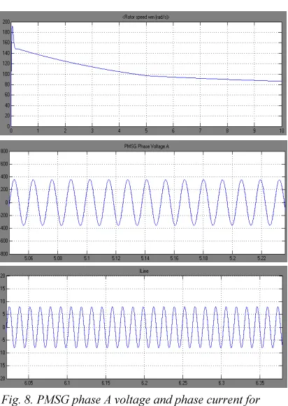
[image:6.595.249.512.79.549.2]The proposed system consisting of PMSG based variable speed WECS is simulated using MATLAB/SIMULINK. The results of simulation are shown in fig 7. It is seen from the figure that the power from the generator increases as the speed of the wind increases, which is indicated by an increase in magnitude of PMSG phase voltage and phase current. It is also seen that the input current of the rectifier is in phase with the voltage waveform, therefore leading to unity power factor. The current controller voltage source inverter is actively controlled to achieve the balanced sinusoidal signals even in the presence of non-linear loads. The waveforms of grid voltage, grid currents and inverter output are shown in Fig 8.
Fig. 7. Wind Speed profile
Fig. 8. PMSG phase A voltage and phase current for wind speed 6m/s.
[image:6.595.313.519.267.558.2]is proved using simulation, a hardware can be constructed in order to implement the controller in real time. Further the maximum power point tracker can be implemented for bigger generators.
Fig. 9. PMSG Phase A Voltage And Phase Current For Wind Speed 8m/S
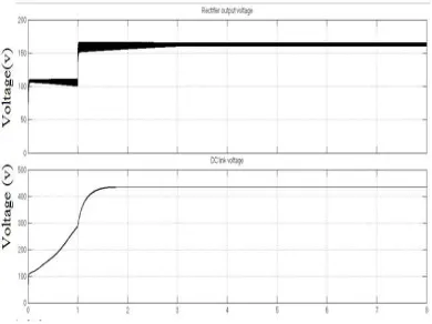
[image:7.595.93.287.197.377.2]Fig.10. DC Link Voltage.
[image:7.595.88.283.431.577.2]Fig.12. THD of load current
6. CONCLUSION
The performance of PMSG based WECS incorporated with MPPT is presented for varying wind conditions. The various components of the proposed system like the wind turbine, dc-dc converter and grid interfacing inverter are modelled first in MATLAB. The complete system is tested for different wind speeds. The MPPT controller achieves its objective of extracting maximum power from the wind at any speed without the knowledge of wind speed. The grid side inverter synchronizes and interfaces the wind energy to the existing grid. The grid interfacing inverter is able to inject real and reactive power into the grid and simultaneously compensates the harmonics and reactive power, thus improving the power quality and maintaining the grid currents balanced and sinusoidal at unity power factor.
REFRENCES:
[1] Sannino.A, “Global power systems for sustainable development”, IEEE General Meeting, Denver, CO, Jun 2004.
[2] Carrasco J.M, Franquelo L.G, Bialasiewicz J.T, “Power-electronic systems for the grid integration of renewable energy sources: a survey”, IEEE Trans. Ind. Electron., vol.53, no.4, 2006, pp.1002-1016.
[3] Singh.M, Khadkikar.V, and Chandra.A, “Grid synchronisation with harmonics and reactive power consumption capability of a permanent magnet synchronous generator based variable sped wind energy conversion system”, IET Power Electron, vol.4, no.1, 2011, pp.122-130. [4] Mukhtiar Singh, Vinod Khadkikar, Ambrish
Chandra, and Rajiv K.VArma, “Grid Interconnection of Renewable Energy Sources at the Distribution Level with Power-Quality Improvement features”, IEEE Trans. on Power Delivery, vol.26, no.1,Jan 2011, pp.307-315. [5] Heier.S, “Grid Integration of Wind Energy
Conversion Systems”, Hoboken, NJ, Wiley, 1998.
[6] Koutroulis.E, and Kalaitzakis.K: “Design of a maximum power tracking system for wind energy conversion applications”, In: IEEE Transaction on Industrial Electronics, vol.53, no.2, April 2006, pp. 486- 492.
[7] Kesraoui.M, Korichi.N, and Belkadi.A, “Maximum power point tracker of wind energy conversion system”, Renewable Energy, vol.36, no.2011, April 2010,pp. 2655-2662.
[8] Sharad W. Mohod, and Mohan V. Awar, “A STATCOM-Control scheme for Grid connected Wind Energy Systems for Power Quality Improvement”, IEEE Systems Journal, vol.4, no.3, Sep 2010, pp.346-352.
[9] Md. Enamul Haque, Michel Negnevitsky, and Kashem M.Muttaqi, “A novel control strategy for a variable speed wind turbine with a Permanent Magnet Synchronous generaor”, IEEE trans. on Ind. App., vol.46, no.1, Jan/Feb 2010.