DATE: PROJECT: CHARGE NO:
SYSTEM DESIGN SPECIFICATION AND
USERS GUIDE
12/11/79
nOCMP MULTIPLEXER M416-E0300-37622
·REV 1.1
BY
1.0 1.1 1.2 1.3 2.0 2.1 3.0 3.1 3.2 3.3 4.0 4.1 4.2 4.2.1 4.3 4.4 4.5 4.5.1 4.5.2 4.5.3 4.5.4 4.5.5 4.5.6 4.5.7 4.5.8 4.5.9 4.5.10 4.5.11 INTRODUCTION PURPOSE
TABLE OF CONTENTS
REQUIREMENT SUMMARY
DESIGN GOALS AND CONSIDERATIONS USER VIEW OF SYSTEM
USERS VIEW OF WHAT HAPPENS PDP11 INTERFACES
BUFFER DESCRIPTOR LIST (BDL) DEFINITION CSR INPUT COMMANDS TO KMC
CSR RESPONSE COMMANDS FROM KMC KMC INTERNAL DESIGN
SECTION OVERVIEW
DETAILED EXAMPLE OF MESSAGE TO BE TRANSMITTED DETAILED INTERNAL VIEW OF INTERACTIONS
MEMORY DEFINITION
BLOCK DIAGRAM OF THE SYSTEM TABLES, QUEUES AND BUFFERS LINE STATUS TABLE
LINE OUTPUT STAT~TABLE (LOST) LINE INPUT STATE TABLE (LIST) CSR QUEUES
NPR INPUT REQUEST QUE NPR OUTPUT REQUEST QUE
MESSAGE CHARACTER ADDRESS BUFFERS MESSAGE WAITING RESPONSE QUEUE RETRANSMIT QUEUE
INTERMEDIATE DATA BUFFERS CONTROL MESSAGE QUE
1.0 INTRODUCTION 1.1 PURPOSE
The purpose of this document is to provide a design overview of KMC DDCMP multiplexer and its interaction with a host PDPll processor. It is also 'intended to provide the PDPll user with the required knowledge to
interface the PDPll host to the KMC multiplexer. 1.2 REQUIREMENT SUMMARY
*
Detailed below is a summary of the Requirements, Goals and non goals of the DDCMP multiplexer. The Functional Specification should be referred to for a complete
definition of multiplexer functionality.
KMC DOCMP MULTI-LINE CONTROLLER
WHAT ARE THE MAJOR OBJECTIVES OF MULTIPLEXER?
Provide 8 lines at 'full or half duplex with'speeos up to 9600 BPS.
DDCMP communications protocol implemented in
firmware providing high reliability and throughput with low host processor overhead.
Provide communications between KMCll and other synchronous interfaces that support DDCMP protocol in a point to point environment.
16 Bit NPR (DMA) transfers for minimum interference with host processor operation.
*
*
WHAT ARE ITS GOALS?
Line level compatability with present DMClI. Support greater than seven (7) outstand'ing messages.
*
WHAT THE MULTIPLEXER IS NOTNot a DMClI modified to JUST scan 7 more lines. Will not provide support of line speeds greater
than 9600 BPS.
Will not support local on board diagnostics.
(Note: Since KMC is loadable, diagnostics can be separately loaded into the KMC). '
Will not support automatic recovery from powerfail.
DESIGN GOALS AND CONSIDERATIONS
CSR control is the same as COMM rOP-DUP.
Note commands differ but interface control is the same.
CSR transfers from KMC to host PDPll take priority over CSR transfers from PDPll to KMC.
Body of all messages reside in PDPlI host. All message headers reside in KMC.
All inquiry control messages reside in KMC. System is primarily a state system.
The states in the -system are controlled by a series of queues, tables and buffers.
Data reception takes priority over data transmission.
Attempt to make the system somewhat self regulating (It won't accept more work than what it can
1.3 DESIGN GOALS AND CONSIDERATIONS
Listed below are some design considerations of the DOCMP multiplexer in relation to other products, interfaces
and internal control. The speed calculations define the max.imum slice of time or state size that may be executed
for each line per character per second.
SPEED CALCULATIONS
KMC
=
5,000,000 instructions per second.CHARACTER RATE
=
8 lines X 9600 BPS=
9600 characters/second8
bits per characterINSTRUCTIONS/CHAR/SEC
=
5,000,000 instr/sec=
520.8 instr/char/sec9,600
char/sec520.8 instructions/character/sec for 1/2 duplex line.
NOTE: The 520.8 instruction/character/sec is for a one way (l/2 duplex) line to arrive at a full duplex two way communication divide 520.8 by 2.
FULL DUPLEX
=
520.8=
260 instructions/character/second2.0 USERS VIEW OF SYSTEM
Below is a visual description of the system from the PDP1l users point of view. All major components of the system are identified.
VISUAL DESCRIPTION OF SYSTEM
I 6 BUFFER TO TRANSMIT
I~---~---~--~---~
I 7 APPLICATION
I-~---~---~~-1---
I B.D.L.I 51 ..
·---~---~--J D R I V E R
4 PDPll
UNIBUS MEMORY
---~----~--~---~-J
I 1 KMC
- - - I 2 MEMORY
---I 31 - LINE STATUS TABLE IN KMC (LST) CONTAINS CURRENT LINE DEFINITIONS 2 LINE OUTPUT STATE TABLE IN KMC (LOST)
CONTAINS CURRENT STATE, HEADER AND NEXT CHARACTER INFO
3 - INTERMEDIATE BUFFER IN KMC (IB) CONTAINS BUFFER OF 8 CHARACTERS TO BE TRANSMITTED
4 - DRIVER INTERFACE IN PDPll
5 - BUFFER DESCRIPTOR L-IST AREA IN PDPl1 6 - DATA BUFFER TO BE TRANSMITTED
2.1 USERS VIEW OF WHAT HAPPENS
The following is a description of the general processes that occur from a users point of view in the
transmission of a message. The reception of a message has a similar process to that of transmission.
WHAT HAPPENS
I 6 BUFFER TO TRANSMIT
I---~--f 7 APPLICATION
I---~---~-~---
I-~---I B.D.L.I 5
1-.... ---D I
R I
---1
II
UNIBUS V I
---1
EI
I R
t
---I
----~--~---~
1
I LST---1 1 !(MC
I LOST I 2 MEMORY lIB.
I
34 PDP;tl MEMORY
Application program (7) passes to driver (4) a request for ·a message to be transmitted. It specifies the BDL MEMBER (5) that contains the address and character count of the buffer to betransmitt~d.
The driver (4) passes the information to the !{MC. The KMC first builds the header information in the L.O.S.T. Table (2).
The KMC then retrieves the BDLMember (5) which defines where in PDP memory the data buffer (6) is and how big
it is.
The KMC then retrieves the first eight characters of the data buffer (6) and places them in the intermediate
The KMC then transmits the header information from the L.O.S.T. (6) table and updates the line status table
(3) •
After the header has been transmitted, a header eRC is transmitted.
Following the header CRC transmission, a character is retrieved from the intermediate buffer (1) and
transmitted and a character from the data buffer (6) is requested to take its place (remember 7 other characters will be t~ansmitted before the character requested is transmitted). The L.S.T. (3) is updated as is required. The previous step is repeated until all characters have been transmitted. the data CRe is then generated and
the LOST (2) is updated.
Upon reception of an ACK or NAK, (after seven retries), the BDL (5) member is set as free and a notification is sent to the driver (4) as to what has happened and the KMC tables and buffers 1,2,3 are updated.
3.0 PDPll INTERFACES
This section discusses the interfaces between the KMC and PDPll. There are three areas of interaction. The Buffer Descriptor List Definition Table in the PDPlI, CSR Input Commands to the KMC from the PDPll and CSR Response Commands from the KMC to the PDPll.
3.1 BUFFER DESCRIPTOR LIST (BDL) DEFINITIONS
In the PDPII an ~rea must be set aside to hold
definitions of messages to be transmitted or received. What is a Buffer Descriptor List? It is a four word entry in PDPll memory that defines to the KMC and the PDPl1 where in PDPII memory a data message is," how many characters are in the message, the line number and
ADDRESS
PDPll BUFFER DESCRIPTOR LIST DEFINITION TABLE
X
X+l X+2 X+3 X+4 X+S X+6 X+7
I STATUS I I
IBUFFER START ADDRESS I
I I NUMBER OF CHARACTERS 14 BITS I
1 MESSAGE I __ ~I~ __________ ~I
'STATUS I I
r-BUFFER~S~TA~R~T~A~D~D~R~E~S~S---~I I INUMBER OF CHARACTERS 14 BITS
I
LMESSAGE 1_----:11...-_ _ _ _ _ ...:..1MEMBER 1
MEMBER 2
X+(N*4-4) I STATUS I I
X+(N*4-3) IBUFFER START ADDRESS I
X+ (N* 4-2) 1 1 NUMBER OF CHARACTERS 14 BITS
I
MEMBER NX+(N*4-l) i-MESSAGE 1
I
I
MESSAGE t
=
DDCMP Message Number from KMC Controller STATUS = The status area is for use' by the PDPl1for keeping track of which BDLs ar~ in use and assigned to transmit and receive lines which are free.
BUFFER START ADDR
=
Start Address of Message Data to be Transmitted.LENGTH = Character Count of Message to be Transmitted.
3.2 CSR INPUT COMMAND TO KMC
The KMC and PDPl! communicate with each other via
Control Status Registers (CSRs). Since both the KMC and PDPll can read and write the CSRs, a control mechanism is required to prevent one CPU from writing while the other CPU is reading.
All input commands to the KMC are issued by an application program to a driver program which is
completed in a series of steps. The driver·program sets RQl to request the use of the CSRfor transfer of data and then waits for the RMC to set RDYl. This wait can be implemented through a delay loop or can wait for an interrupt. The delay loop is not recommended. The KMC will then set RDYl when it is ready to accept an input. After the RDYI has been set by the KMC.
The PDPl1 driver loads the CSRs with the command and its assoc iated parameter·s.When the parameters have been loaded into the CSR, the RDYI is cleared to inform the KMC that the parameters may be read.
15 14. 13
TRIBUTARY NO.
KMC CONTROL INPUT COMMANDS
GENERAL FORMA'!'
B 7 6 5 4 3
BJI BESERVm NOT COMMAND IEI tISE:D StmCODE
LINE NUMBER NO'!'
PASSWORD/BDLAODRESS PASSWORD!BOL ADDRESS
COMMAND VALUE
o
1 2 3· COMMAND VALUE 0 0 0 0 0 0 0 0 COMMANDSOB CODE
0 1 2* 3 4 5* 6 7
COMMAND ~ES
COMMAND
DESCRIPTION
Master Control
LineControl'-Message Control
st.atus
MASTER CONTROL COHHANDS
·COMMAND .
DESCRJ:P1'ION
~itSystem
..."...~/ ....
. 'ro 'lPANSMIT .
PARAMETERS
N/A
..
Reset/Set to. DDCMP Mode LN' , TRIB • Enter HOP Mode LN
t,
TlaBI,PASSWORD
Ter.minateActivity Set Line Scan Length
(No. of Lines to Scan) Set HOP Mode Password
for ForceaEntry
Set BDL Base Address
Set Modem CSR Address . (Note ~ also enables
modem . control for all
lines.
LNt, TRIB
t
LN.
LN . , PASSWORD
BDL ADORESS, 'l'RANS., RCV.
CSR Address of
modem· control
COMMAND VALUE 1 1 1 COMMAND VALUE 2 2 COMMAND VALUE 3 3 3
LINE CONTROL COMMANDS COMMAND
SUB CODE DESCRIPTION PARAMETERS
0 Set Line Up LN # (TRIB #) 1 Set Line 1/2 Duplex LN #
2 Set Line Down LN # (TRIB #)
MESSAGE CONTROL COMMANDS COMMAND
SUBCODE
o
1
DESCRIPTION PARAMETERS
Transmit Message LN i,BDL Member
i of messages, TRIB #
BDL Member for use BDL Member, in Message Reception LINE i
STATUS CONTROL COMMANDS COMMAND SUB CODE
o
1 2 DESCRIPTION Request Line Status ReadKM'C Memory write KMC Memory(Note an automatic read of the data store will take place- for verifi-cation.
PARAMETERS
(LN i, . (TRIB # 1) )
KMC Data Mem'ory Address
KMC Data Memory Address & Value to be stored.
15
HlN __ .. _ ...
1'RZBC'TARY NO.
I<MCCONTROL l:NPOT COMMANDS
RESET/SET DDCMPMODE
8 7 6 5· 4 3
LINE NDMBER N01'
•
EMC CON'l'ROL INPUT COMMANDS
ENTER MOP MODE
15 14·13
KIN __ .. __
. ~RIBOTARY NO. '. LINE .NOMBER
PASSWORD CB.A.MCTElt2
PASSWORD CB.A.MC'l'ER 4
,. 7
6
5 4 3,
PASSWORD CHARACTER 1
PASSWORD CHARACTER 3
15 14. 13
XMC CON'l'ROL INPUT COMMANDS TEBHINA'l'E .~~IVI'l'Y
8 7 6 5 4 3
EMC CONTROL INPO'l' COMMANDS SET LINE SCAN LENGTH
8 7 · 6
5
,
3
iQI ReSER\1!!DNOT COMMAND :tEI
tJSED ·St1SCODE
TRIBUTARY NO.
KMC CONTROL INPUT COMMANDS MODEM CONTROL CSR ADDR
8 7
RJI
LINE NUMBER NOT
6 5 4 3
RESERVED NOT COMMAND lEI USED 1 SUB ODE 1 RESERVED ROY! ~ NOT CCM-WID
. 'ED E CODE :
15 14·
13
Me CONTROL INPUT COMMANDS BOL BASE ADDBESS
8 7 6 5 4 3
15 14. 13
TRIBUTARY NO.
mc
CON'l'ROL INPtT'l' COMMANDSSE~ LINE UP
8 7 '6 5 4 3
15
BON .,...._11. ..
TRIBO'l'ARY NO.
XMC CONTROL INPO'l' COMMANDS SE'l' LINE ~ DUPLEX
8 7 6 S 4 3
RJI RESER\lED NO'l'COMMANl) I;EI
OSED S.UBCODE
15 14. 13'
TRIBUTARY NO.
XMC CON'l'ROLINPO'l' COMMANDS SE'l'LZNE DOWN
8, 7 6 5 4 3
~ \3LCEi!CEk,ft.'IP\ NO'!' COMMAND
~.. ~v..., CSED StlBCODE IEI
15
mc
CONTROL INPOT COMMANDSTRANSMIT MESSAGE
,
8 7 6 S .. 3
SDL MEMBER NO.
COMMAND
me
CONTROL INPUT COMMANDSSOL MEMBER FOR OSE IN MESSAGE RECEPTION
15
14
13· S 7 6 5 4 3NO'!'
coMMAtm
HJN "aJI BESIE2VEO IEI
tlSED OSUBSODE 1
KMC CONTROL INPUT COMMANDS READ KMCll DATA MEMORY
15 8 7 6 5 4 3
RON
RJI
RFSERVED USED NOT IEINOT
US
KMC CONTROL INPUT COMMANDS WRITE KMCll DATA MEMORY
lS 8 7 6 5 4 3
RON R'JI RESERVED NOT COMMAND lEI
USED OSUB· ODE 0
TRIBUTARY NO. NOT CCMWID
DE .
15 14 · 13
RON
t.rRnOWUtY NO.
bC CONTROL J:NPOT COMMANDS
REQUEST LINE S~ATOS
•
8 7 6 5
BJI
IRESERVEDLINE NUMBER . Ncr.t'
4 3
1:1OT . COMMANJ)
I~I
3.3 CSR RESPONSE COMMANDS FROM KMC
Corresponding to the CSR input commands there are a
series of output commands. Commands from the KMC to the PDPllalways take priority over an input command
request. The method used for implementing output commands are as follows:
The KMC loads the CSRs with the parameters required for a given command;
theRDYO bit is set and an interrupt is generated to the PDPll indicating thePDPll should read the CSRs:
the driver programs retrieves the CSR data and clears the RDYO bit to indicate the transfer is complete.
15 14. 13 KJN a - .. _ _
'mIBt11'ARY NO.
1Q1C CON'1'ROL 00'1' COMMANDS
GENERAL FO:RMA~
8 7 6 5 4
...
--
IEO
3 COHMAND • NOTStmCODE trSED
BDL·MEHBER NO.
. MESSAGE NO. /ltEASONCOMMAND
VALUE
o·
12
3
.
.
COMMANl)"ftPES
DESCRIPTION
Positive Responses
Control-Negative Bespoztses.Control
Message Reception
Control
Status Responses
COMMAND VALUE 0 0 0 0 0 COMMAND VALUE 1 1 1 COMMAND VALUE 2 2
POSTIVIE RESPONSE CONTROL COMMAND
SUB CODE DESCRIPTION 0 Init Complete
1 Set/Reset Complete 2 Activity Terminated 3 MOP Mode Entered* 4 Message Acknolwedged
NEGATIVE RESPONSE CONTROL COMMAND
SUBCODE DESCRIPTION 3 Error Threshold
Reached
5 Messaged Naked 6 Returned too many
receiver buffers for line
MESSAGE RECEPTION CONTROL COMMAND
SUBCODE
o
1
DESCRIPTION Message Received Request BDL Member for Reception of Message
PARAMETERS N/A
LN #, 'TRIB t LN i, TRIB i
LN i, TRIB :3
Message i, BDL t
PARAMETERS LN i, TRIB t
LN i, TRIB i, BDL Member LN i, MEMBERt
PARAMETERS LN ',TRIB i, BDL MEMBER MSG t
STATUS COMMAND COMMAND
VALUE SUBCODE DESCRIPTION PARAMETERS
3 0 1st 4 bytes of line LINt TRIB
status table for Bytes 0-3 of LST specific line. for line.
3 1 Last 4 bytes of .LINt ·TRIB
line status table Bytes 4-7 of LST for specific line. for line.
3 2 Dump of specified Oata Memory
DC CON'l'ROLOU'l' COMMANDS
INITIALIZATION COMPLETE
15 14. 13 8 7 6 5
COMMAND TYPES
4
IEO COMMAND SOBCODE 1JSED NOT
COMMAND VALUE DESCRIPTION
g
1
2
3
Positive "Responses Control Negative Responses Control Message Reception Control
15
BON
a-._ ...
TRIBUTARY NO.
I<MC CON':ROL 00': COMMANDS
SET/RESET COMPLETE
8 7 6 5 4 3
lEO LINE NtlKSER
COMMAND
SOBCODE
NO'!'
15 14. 13
'l'RIBtl'I'ARY NO.
DC CONTROL OUT COMMANDS
ACTIVITY TE~NATED
8 7 6 5 4 3
NOT lEO COMMAND Ncn
KMC CONTROL OO~ COMMANDS MESSAGE ACKNOWLEDGED
15 8 7 6 5 4 3
LINE .NOMBER
BDL MEMBER NUMBER MESSAGE NUMBER
NOT
15
KlN ... _ ....
'.rRIBOTARYNO.
I01C CONTROL OOT COMMANDS SET/RESET FAILED
8 7 ' 5
4
3
NOT
IEO COMKANJ) SUSCODE
15 14. 13
RlN ... _ ....
EMC CONTROL OOT COMMANDS ERROR THRESHOLD REACHED
8 7 6 5 4- 3
:IEO
, . ' NOl'L KJ!O PJ:ISERVEC .
NOT,
1.0 1.1 1.2 1.3 2.0 2.1 3.0 3.1 3.2 3.3 4.0 4.1 4.2 4.2.1 4.3 4.4 4.5 4".5.1 4.5.2 4.5.3 4.5.4 4.5.5 4.5.6 4.5.7 4.5.8 4.5.9 4.5.10 4.5.11
INTRODUC'l' I ON PURPOSE
TABLE OF CONTENTS
REQUIREMENT SUMMARY
DESIGN GOALS AND CONSIDERATIONS USER VIEW OF SYSTEM
USERS VIEW OF WHAT HAPPENS PDP11 INTERFACES
BUFFER DESCRIPTOR LIST (BDL) DEFINITION CSR INPUT COMMANDS TO KMC
CSR RESPONSE COMMANDS FROM KMC KMC INTERNAL DESIGN
SECTION OVERVIEW
DETAILED EXAMPLE OF MESSAGE TO BE TRANSMITTED DETAILED INTERNAL VIEW OF INTERACTIONS
MEMORY DEFINITION
BLOCK DIAGRAM OF THE SYSTEM TABLES, QUEUES AND BUFFERS LINE STATUS TABLE
LINE OUTPUT STATE TABLE (LOST) LINE INPUT STATE TABLE (LIST) CSR QUEUES
NPR INPUT REQUEST QUE NPR OUTPUT REQUEST QUE
MESSAGE CHARACTER ADDRESS BUFFERS MESSAGE WAITING RESPONSE QUEUE RETRANSMIT QUEUE
KMC CONTROL OUT COMMANDS
MESSAGENACKED
15 14. 13 8 7 ' 6 5 4 3
lIJN a -.. _ ....
no
.. fL
LINE NmmER
m,
.~, ~t.rRIB01'AltY NO.
SDL MEMBER ~~ER REASON
COMMAND SOBCODE
N01'
!(MC CONTROL OOT COMMANDS . .
TO MANY RECEIVE BUFFERS
15 14. 13 8 7 6 5 4 3
lEO
TRIBUTARY NO. LINE ·.NTJMBER
BDL MEMaER.NUMBER
KMC CONTROL OUT COMMANDS
STATUS RESPONSES FORMAT 1
15 8 7 6 5 4 3
- RON NOT- lEO
TRIBUTARY NO. LINE NUMBER a»m.ND
=
3LINE FLAGS - .. . .LINE 'STATUS'
"
. .
:. ":NEXT -MSG # 1£0 BE:.TRANSMITTED· TEMP.DATA
STATUS RESPqNSES FORMAT 2
15 8
'.rRIBOTAltY NO.
LINE NUMBER
.
#-.MSGS RECEIVED iNAKS SENT
7 6 5 NOT
4
lEO
3
COMMAND NOT
SUBCODE =1 USED
# ACKRCVD FOR MSG·SENT
•• '" ' 0 . . . .
KMC CONTROL OUTPUT COMMANDS READ KMCll DATA MEMORY
8 7 6 5 4 3
Nor'
MAR PAGE MAR LOW
l(MC CONTROL OUT COMMANDS MESSAGE RECEIVED
15 8 7 6 5 4 3
NOT
lEO
~RIBOTAltY NO. LINE NOMBER
,
-BDL MEMB~R WOMBER MESSAGE NUMBER
NOT
4.0 4.1
- 4.2
KMC DESIGN
The KMC DDCMP multiplexer is a state driven system, based on a series of queues, tables and buffers. Each state per line is less than or equal to 260 KMC
instructions. The following sections describe the KMC memory organization, tables and queues used in the operation and control of the multiplexer.
The secion starts out with a detailed example of a message transmission and steps involved. This is
followed by a memory map, and block diagram of the sytem and definition of tables. The last section contains a definition of various states the system may be in. DETAILED EXAMPLE OF MESSAGE TO BE TRANSMITTED
1. Application program passes-to driver BDL Base address.
2. PDPll driver passes BDL base to KMC.
3. Application program request a transmission of a message providing PDPll Driver with BDL member
control address of message data and. numbe.r of messages to be transmitted.
4. PDPll Driver requests CSR transfer.
s.
KMC acknowledges request when input que is available.6. KMC retries CSR/Retransmit data and places data in input.
7. KMC command interpreter sees input data in queue. It determines from queue data line data is to be ,t'ransmitted on. If line is busy., it leaves data in
que and waits to check it next time around. It then dertermines if a control message is in the control out que. If so, it is prepared for
transmission. Else it sets the line to output state I and places CSR data into output me sage charac·ter address buffer • The command interpreter state is then sat back to O.
8. The KMC then waits unt-il select flag is set. If set, the KMC then builds the message header.
9. TheKMC then builds a BDL address and places a read request into the output NPR queue and set BDL flag. 10. The KMC then performs THE NPR states which request
11. After completion ,of the read, the message address contained in the BDL is placed in. the Output
message character address table.
12. An output.request is placed in the NPR queue to set the BDL as in unuse by the KMC.
13. The!(MC then requests that the first four words 8 character of the message be stored in the
intermediate buffer.
14. After eight characters are buffered, the LST is updated, the header of the message is then
transmitted.
15. After the header and eRC of the header is transmitted, the first character of the da~a
message is transmitted.
16. After every even character of the message has been transmitted from the intermediate buffer, an NPR INPUT QUEUE request is made to get two more
characters from the PDPll for transmission until entire message has been retrieved •
•
17. At this point in time, if multiple messages (pipelined messages) are to ~e transmitted, the next BDL address is calculated the BDL and next message flags are set and th. address of the next message is retrieved. An NPR INPUT queue request
is then made for a charcter pair of the next
message while the current message is finishing its transmision.
18. Upon completion of the transmission of the message, the message pending flag is set and the BDL member
i, line t and tributary t are placed in the message waiting response que.
19. If the message is acked, then the entry in the message pending que is cleared. A request is
placed in the OUT NPR Queue to release the BDL. A transmit complete eSR output request is placed in the eSR output que.
20. If the message is nacked,the entry in the message pending que is removed and placed in the 'retransmit que. An error counter is then incremented.
.
DC 'rBANSMI'l'S HEADER FROM LINE STATE QUEUE
---
---~l
,
.I RETRIEVES CBABACTER
: FROM IDl
I . .
I
I
. I·
PLACE IT IN 'l'RANSMIT'l'ER AND TRANSMIT
1
BE'rRIEVE CBABAC'l'ER FROMID
1
.
PLACE IN TRANSMITTER
I
___ . _ _ _ _ ...l
I
t
!
REQUES INPUT NPR QUEtJE II I CHARACTER 1 ' R A N S F E R J
I I :
I
I,"
,- - - -
-NPR iREQUES1---"'--- ----'"
"
1 I ' I'.rB
"
'
,...
-.-
-
-
-
--..,
II
r
BUILD NEJb. MESSAGE CHARACTERI
I
.!
.
ADDRESS ~OFFERL_J~I-'''''
- - - - -
J
\..._---.
PLACE BDL MEMBER, LN
t,
TRIB i, MSG i IN WAITING. RESPONSE QUEUEt
I
..
1
,. -- - ·WAIT
'''--"'1
l
i
WAI'r
•
:- - -
~ ~
FRpM WAI'!' :RESPONSEI I "I I I I I I I I
+
PLACE IN RETRANSMIT QUEOE
I
,
,
----"
..
I WAI'!' COMMAND INTERPRETER
\ (Retrans. priol:ity over CSR Queue)
'---
-.'
I+
RETRANSMIT MESSAGE
---~
UPDATE LST ACK/NAK
I
I
~
NPR OOTPUT REQUEST QUE BOt. MEMBER
RELEASED - - -
-I
I
..
REQUEST CSR OUTPUT QUEUE TRANSFER a "
I
+
POPll
... UPDATE BOL LIST
'l'YPE., MSG I, BDL MEMBER - - - -;. PDPll DRIVER ACCEPTS PARAMETERS
!
4.3 MEMORY DEFINITION
.0 777 LINE STATUS TABLE (LST)
1000 - 1077 LINE OUTPUT STATE TABLE (LOST) 1100 - 1177 LINE INPUT STATE TABLE (LIST)
1200 - 1277 INTERMEDIATE TRANSMIT BUFFERS(ITB) 1300 - 1466 SPARE
1467 - 1477 CSR INPUT BUFFER
1500 1677 CONTROL MESSAGE OUTPUT OUE 1700 - 2077
2100 - 2207 2210 - 2317 2320 - 2427
CONTROL MESSAGE INPUT QUE
PRIMARY OUTPUT MSG ADDR BUFFER SECONDARY OUTPUT MSG ADDR BUFFER PRIMARY INPUT MSG ADDRESS BUFFER 2430 - 2547 SECONDARY INPUT MSG ADDRESS BUFFER 2550 - 2777
3000 - 3377 3400 - 3777 4000 - 4377 4400 - 4777 5000 - 5110 5111 - 6977 6400 - 6777 7000 - 7640 7640 - 7661
SPARE
NPR OUTPUT REQUEST QUE
MSG WAITING RESPONSE QUEUE 1ST HALF
NPR INPUT REQUEST QUEUE
CSR OUTPUT QUEUE TIMEoRS
SPARE
MESSAGES WAITING RESPONSE QUEUE 2ND HALF RETRANSMIT QUE
~.4
BLOCK DIAGRAM OF SYSTEMLINE SE~CT
I
I
1
bENERAL~OUSE
FLEANING ~ND AAIN'l'. I !'I IF
DLE STATES ~, REQUEST NPR/CSR FUNCTION REQUEST OUTPUT • MESSAGE l1li
1
.
INPUTSCAN
,
...
-
...
, IF
ENO STATEE} ' . . , .. f
...
REQUEST NPR/CSR FUNCTIO~ REQUEST OUTPUTI
MESSAGE , I '. NPR.';;·. STATES <II' SOH STATES ~...
~. ...••
REQUEST NPR/CSR FUNCTION REQUEST OUTPUT ~MESSAGE ~
NPR CSR
STATES STATES
---'.
_ ..---
....
-
....
.... _ _ _ _ .11... _ _ . . -_ _ _ _ - . . '.
1
I'
REQUEST
NPR
. STATE
. REQUEST OUTPUT MESSAGE EXECUTION COMMAND NPR
agQUEST REQUEST CSR
MEMORY LAYOUT LINE STATUS TABLE
MEM ADDR TRIB t
LINE t
LINE 0 0 0 0 123 4 5 6 7
TRIB 1 0 1 0
TRIB 2 0 2 0 TRIB 3 0 3 0 TRIB 4 0 4 0
TRIB 5 0 5 0
TRIB 6 0 6 0 TRIB 7 0 7 0
LINE 1 1 0 0 1 2 3 45 6 7 TRIB 1 1 1 0
TRIB 2 1 2 0 TRIB 3 1 3 0 TRIB 4 1 4 0
TRIB 5 1 5 0 TRIB 6 1 6 0
TRIB 7 1 7 0
LINE 7 7 0 0, 1 2 34 56 7 TRIB 1 7 1 0
TRIB 2 7 2 0 TRIB 3 7 3 0 TRIB 4 7 4 0 TRIB 5 7 5 0 TRIB 6 7 6 0 TRIB 7 7 7 0
LINE TRIBUTARY ENTRIES
o
= LINE/TRIB STATUS
1
=
LINE/TRIB FLAGS 2 = FLAGS3
=
NEXT MESSAGE TO BE TRANSMITTED4
= NUMBER OF ACKS RECEIVED
,5
=
NUMBER OF MESSAGES RECEIVEDLINE STATUS BYTE MEANINGS
BYTE NAME BIT t DEFINITION
0 LINE BIT 0 0
=
LINE DOWN 1=
LINE UP STATUS BIT 1 0=
DDCMPMODE 1=
MOPBIT 2 0
=
XMIT NOT ACTIVE 1=
ACTIVE BIT 3 0=
RECEPTION NOT ACTIVE 1=
ACTIVEBIT 4 0
=
NO START PENDING 1=
START PENDINGBIT 5 0
=
SPARE 1=
SPAREBIT 6
o =
FULL DUPLEX 1=
1/2 DUPLEX BIT 7 SELECT FLAG FOR 1/2 DUPLEX TURN AROUND0
=
NO 'XMIT1 LINE BIT 0 0
=
NO START RCVD 1=
START RCVD FLAGS 1 BIT 1 0=
NO NAK RCVD 1=
NACK RCVDBIT 2 0
=
NO REP RCVD 1=
REP RCVDBIT 3 0
=
NO XMIT CONTRO MSG 1=
XMIT CONTROL MSG BIT 4 0=
NO ACKRCVD 1 = ACK RCVDBIT 5' 0
=
NO STACK RCVD 1= STACK RCVD
BIT 6BIT 7 0 = NO START PENDING 1
=
START PENDING 2 TEMPORARY DATA MSG tFROM ACK OR NAK3 NBRNXT NEXT MESSAGE NUMBER TO BE TRANSMITTED 4 NBRACK NUMBER OF ACKs RECEIVED FOR MESSAGE SENT 5 NBRRCV NUMBER OF MESSAGES RECEIVED
4.5 TABLES AND QUES AND BUFFERS
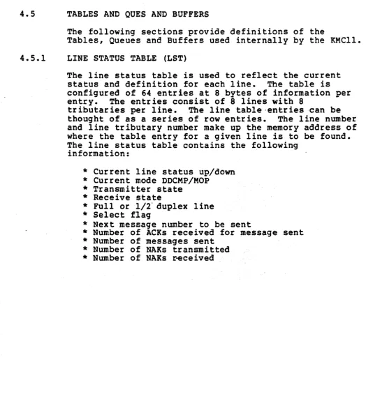
4.5.1
The following sections provide definitions of the
Tables, Queues and Buffers used internally by the KMC11.
LINE STATUS TABLE (LST)
The line status table is used to reflect the current status and definition for each line. The table is configured of 64 entries at 8 bytes of information per entry. The entries consist of 8 lines with 8
tributaries per line. The line table·entriescan be thought of as a series of row entries. The line number and line tributary number make up the memory address of where the table entry for a given line is to be found. The line status table contains the following
information:
*
Current line status up/down*
Current mode DDCMP/MOP*
Transmitter state*
Receive state*
Full or 1/2" duplex line*
Select flag*
Next message number to be sent*
Number of ACRs received for message sent*
Number of messages sent [image:52.617.43.568.77.672.2]4.5.2 LINE OUTPUT STATE TABLE (L.O.S.~.)
ADDR
The Line Output State Table consists of eight subtables. One for each output line. Each subtable contains eight entries which contain the current state of the line and the header of the current output message except CRC values. The first byte of each subtable is the current state of the line. This state value is used as an indexed branch to execute the =next series of instructions to keep the line operating properly. The remainder of the table contains the header data of the current message being transmitted.
LINE OUTPUT STATE TABLE LINE
TRIB
BASE BASE BASE WORK
STATE BDL LOW UP BDL BOL
*
MSGS1000 1 2 3 4 5 6 7
1010 STATE BDRl HDR2 HDR3 HDR4 CRC1/NEXT CRC2/NEXT CHAR IN CHAR AVAIL.
1077 n n
..
"
"
LINE OUTPUT STATE TABLE CONTROL MSG
1 2 3 4 5 6 7
STATE ACK t LSTL LSTH INDEX NAK COUNT 4.5.3 LINE INPUT STATE TABLE (L.I.S.T.)
STATES AD DR
The Li~e Input State Table is configured exactly as the Line Output
State Table except that it is used for input rather than output. LINE INPUT STATE TABLE
1100 1 2 3 4 5 6 7
STATE HDRI HDR2 HDR3 HDR4 CRCI/NEXT CRC2/NEXT CHAR IN CHAR AVAIL •
.
1170
"
n.4~5.4 CSR QUEUE
CSR OUTPUT QUE ENTRIES
BYTE 0
=
SUBCOMMAND 1=
LINE &TRIB # 2=
DATA BSEL 3 3 = DATA BSEL 4 4=
DATA BSEL 5 5 = DATA BSEL 6 6 = COMMAND TYPECSR INPUT QUEUE
BYTE 0
=
COMMAND (BITS 0,1)1
=
SUBCOMMAND (BITS 2,3,4)2
=
LINE # (BITS 0-3) & TRIB # (BITS 4-7) 3=
BDL ADDRESS MIDDLE BYTE/DATA .4
=
BDL ADDRESS LOWER BYTE/DATA4.5.5 NPR INPUT REQUEST
The NPR input request queue is the only interface that allows NPR input transfers between the KMC and the PDPll. There are two basic types of input NPR transfers in the system: message data and B.D.L. data. To request a BDL transfer, the line number is entered into the NPR Que with BDL bit set (bit 4) and with either the primary or
secondary message character buffer bit set (bit 5). Bits 0-3
indicate the line number that is requesting the transfer and point tc the message character buffer u~ed. Bit 4 if on requests that the contents be placed not in the intermediate buffer for the line, but
in the message character address buffer. Bit 5 indic~tes whether the BDL data is to be in the primary or ,econdarymessage character
address buffer. For a simple message character input only, the line number is entered and the retrieved data characters are placed in the intermediate buffer for the requesting line.
4.5.6 NPR OUTPUT REQUEST QUEUE
The NPR output request que operates similar to that of the input
ENTRY 1 ENTRY 2 ENTRY 3
LINE
*
ENTRY 1ENTRY 16
NPR CHARACTER INPUT REQUEST QUEUE LINE'
ENTRY 2
LN.
ENT.3
LN.
ENT. 15
NPR CHARACTER OUTPUT REQUEST QUEUE
CHARACTER A CHARACTER B ADDR
II
"
"
"
"
"
CHARACTER" A CHARACTERB ADDR
LINE #
4.5.7 INPUT/OUTPUT MESSAGE CHARACTER ADDRESS BUFFERS
The Output Message Character Address Buffers are the main interface to the NPR queue. These buffers contain the address of where the next two characters for transfer from the PDPll are stored.,· It also contains the character count of the message and the count of the number of characters retrieved from the PDPll. The tributary number and current message transmit number are also stored in this buffer. An example of its use is after a character pair is transmitted, the line number is placed in the input NPR queue. The input NPR 'queue accesses the output message character address buffer to find the address of the next character pair to be transmitted.
There are four message character address buffers - two (2) for input a'nd two (2) for output. Th'=e reason for redundancy is to save time during pipelined input or output messages. The "next" Input/Output Message Character Address buffer is readied during use of the primary buffer. As soon as the primary buffer is complete, a buffer flip flop takes'place and the secondary is now the primary buffer
OUTPUT DATA CHARACTER ADDRESS BUFFER
BYTE 0 1 2 3 4 5 6 7 8
TRIB 31 BOL ADDR CHAR COUNT I t OF CHAR IBOL tl t OF
LINE 1 1 1 I TRANSFERRED I I MSGS
LINE 2 I I I I 1 I
LINE 3 I
. I
I
I
I I•
,
II
I
. I
I
LINE 8 I I I I I I
INPUT DATA CHARACTER ADDRESS BUFFER
BYTE 0 1 2 3 4 5 6 7 8
BDL
t
BDL ADOR CHAR COUNT I t OF CHAR IODD BYTEtLINE 1 I I RECEIVEDS I RECEIVED'
LINE 2
I
I'
II
I fLINE 3
,"
I I I I.
I I I I I jLINE 8
I
I
II
II
WAITING RESPONSE BUFFER
LINE t TRIB t MSG t IBDL MEMBER I
ENTRY 1 I
I .
ENTRY 2
I
'I
ENTRY 3
I
I
• f I
• I I
•
I
I
4.5.8
4.5.9
4.5.10
MESSAGE WAITING RESPONSE QUEUE
After a message has been transmitted, its line number, tributary number, message number and BDLnumber are entered into the waitin response queue. This queue is a holding area containing all
pertinent information concerning the message until the message disposition can be determined. If the message is acked, the BDL member is released, the queue entry cleared, and the PDPll is notified of the transmit. If the message was naked and seven retries have not occurred, the queue entry will be cleared and tl data will be entered into the retransmit que.
RETRANSMIT QUE \
This queue contains informatidn required to retransmit a message that was NAKED or failed to get an acknowledgement. This queue j
examined and takes priority over the CSR input 'request que from the PDPll.
INTERMEDIATE TRANSMIT BUFFER
There is one intermediate buffer per line in the system. This buffer area provides an input buffering function between
characters being sent from the PDPll. The ITB keeps eight (8) characters buffered ahead of the transmitter such that if a
ADDR 120 121 122
• • •
•
127
ADDR 130 131 132
•
•
• •
137
INTERMEDIATE TRANSMIT BUFFER
0 1 2 3 4 5 6 7
DATA DATA rATA DATA ~ DATA DATA DATA
n II II n ft
"
"•
•
..
,ft II tI ftINTERMEDIATE RECEIVE BUFFER
0 1 2 3 4 5 6 7
4.5.11 CONTROL MESSAGE QUEUE
The control message queues are used to hold control messages that are to be transmitted as soon as the line
is free. There are two (2) queues - one for input message reception and the second is for message
transmission. Position in the queuedefi~es line and tributary, thus entry nine in the que Is for line one, tributary one. To determine the line and tributary number, the queue entry is divided by eight. The
integer from the dIvision gives the line number and the remainder is the tributary number. Each queue entry is two bytes long_ The first byte defines the message type and the second the subtype.
,..
LINE 0 LINE 0 LINE 1 LINE 1 LINE 2 LINE 3 LINE
•
Type O,S Bi'b Type Sub1YPe Type ~ '-'YpeS~
LINE 4 LINE 5 LINE 5 LINE 6 LINE 6 LINE j LINE 7
~ Type SUb~ Type ~ Type SubType
4.6 SYSTEM STATES