JUDUL:
Saya
PSZ 19:16 (Pind. 1/97)
UNIVERSITI TEKNOLOGI MALAYSIA
BORANG PENGESAHAN STATUS TESIS·
THE EFFECT OF ECCENTRICITY AT BEAM SUPPORT
TO BEAM STIFFNESS
SESI PENGAJIAN: 2005/2006
AHMAD ZURISMAN BIN MOHD ALI (HURUF BESAR)
mengaku membenarkan tesis (PSMISaIjanaIDelEler Falsafah)* ini disimpan di Perpustakaan Universiti Teknologi Malaysia dengan syarat-syarat kegunaan seperti berikut:
I. Tesis adalah hakmilik Universiti Teknologi Malaysia.
2. Perpustakaan Universiti Teknologi Malaysia dibenarkan membuat salinan untuk tujuan pengajian sahaja.
3. Perpustakaan dibenarkan membuat salinan tesis ini sebagai bahan pertukaran antara institusi pengajian tinggi.
4.
*
* Sila tandakan (v'')D
SULnD
TERHAD[2]
TIDAK TERHADP
(Mengandungi maklumat yang berdaIjah keselamatan atau kepentingan Malaysia seperti yang termaktub di dalam AKTARAHSIARASMII972)
(Mengandungi maklumat TERHAD yang telah ditentukan oleh organisasilbadan di mana penyelidikan dijalankan)
Disahkan oleh
(TANDATANGAN PENULIS) (TANDATANGAN PENYELIA)
Alamat tetap:
45 .fALAN 4A,
DR REDZUAN ABDULLAH
AMPANG JAYA,
68000 SEL4lSGORDARIIL EHSAN Nama Penyelia
Tarikh:
CATATAN:
OKTOBER 2005 Tarikh: OKTOBER 2005
*
Potong yang tidak berkenaan.** Jika tesis ini SULIT atau TERHAD, sila lampirkan surat daripada pihak berkuasalorganisasi berkenaan dengan menyatakan sekali sebab dan tempoh tesis ini perlu dikelaskan sebagai SULIT atau TERHAD.
Signature
Supervisor
Date
*
Delete as necessary....
~
... .
Dr. Redzuan Abdullah
THE EFFECT OF ECCENTRICITY AT BEAM SUPPORT TO BEAM STIFFNESS
AHMAD ZURISMAN BIN MOHD ALI
A project report submitted in partial fulfillments ofthe
requirements for the award of the degree of
Master of Engineering (Civil- Structure)
Faculty of Civil Engineering
Universiti Teknologi Malaysia
I declare that my project report entitled "The Effect of Eccentricity at Beam Support
to Beam Stif.foess" is the result of my own research except as cited in references. The
project report has not been accepted for any degree and is not concurrently submitted
in candidature of any other degree .
Signature
Name
Date
...
~
... .
Ahmad Zurisman bin Mohd Ali
III
rro
my 6efO'Vea sister, 6rotfiers ana refatives, tfianlq for endless support.rro
my parents, )lffafiyarfiamafi J{jfi CJ?szfiimafi Sufaiman ana)lffafiyarfiam :Mofia)lli' 'J{apiafi, our wontfetju[ memories togetfier were tfie inpsiration for me to move
forward.
Acknowledgement
Alhamdulillah, in completion of this projet report, i'm blessed with so many
contacts which provide useful guidance. I wish to express my highest gratitude to my
supervisor Dr Redzuan Abdullah from Structure and Material Department, Faculty of
Civil Engineering, Universiti Teknologi Malaysia, for his wonderful ideas,
guidances, advises, critics and encouragement.
I'm also indebted to Kolej Universiti Teknologi Tun Hussein Onn (Kuittho) for
providing the opportunity and funding me to further my study. Appreciation for
lecturers in Faculty of Civil Engineering, Universiti Teknologi Malaysia for
marvellous learning experience.
To my fellow graduates students,my housemates, colleagues and others, thank you so
ABSTRACT
A beam reacts to loading through bending action. Therefore, beam bending stiffuess
can be represented by deflection. Theoretically, beam stiffuess is governed by span
length, elastic modulus, moment of inertia and support type. In the analytical
analysis, beams are assumed simply supported or fixed supported However, based on
real cases and lab experiments there are other factors that are not included theoretical
equation but effect to the beam stiffuess Factors such as eccentricity between beam
neutral axis and beam support (vertical eccentricity), pour stop stiffuess in composite
beam/slab effect and column size effect were analyzed in this study. The effects were
studied using plane stress element finite. Pour stop stiffuess were modelled using
spring element. From the analysis, vertical eccentricity does not give significant
effect to beam stiffuess and it can be neglected. The pour stop provides stiffuess of
25000kN/m at the outer support. Beam deflection is independent with column
ABSTRAK
Rasuk bertindak balas terhadap pembebanan me1alui lenturan. Oleh itu, kekukuhan
lenturan rasuk boleh diwakili oleh pesongan. Secara toeri, kekukuhan rasuk
dipengaruhi oleh panjang rentang rasuk, modulus e1astik, momen sifat tekun dan
jenis penyokong. Di dalam analisis, rasuk dianggap disokong secara sokong mudah
atau sokong tegar. Bagaimanapun, terdapat beberapa faktor yang mempengaruhi
kekukuhan rasuk yang tidak termasuk di dalam persamaan teori berdasarkan kes-kes
sebenar dan eksperimen makmal. Faktor seperti kesipian antara paksi neutral rasuk
dan penyokong (kesipian tegak), kekukuhan acuan hujung rasuk pada papak
komposit, dan saiz tiang di analysis dalam kajian ini. Kesan-kesan ini di kaji dengan
menggunakan tegasan satah unsur terhingga. Acuan hujung di model dengan
menggunakan unsur spring. Daripada analisis unsur terhingga, didapati bahawa
kesipian menegak tidak memberi impak yang signifikan terhadap kekukuhan rasuk
dan ianya boleh diabaikan. Acuan hujung mempunyai nilai kekukuhan sebanyak
25000kN/m pada bahagian luar penyokong papak komposit. Pesongan rasuk tidak
dipengaruhi oleh pesongan tiang apabila lebar tiang bersamaan tiga kali kedalaman
vii
TABLE OF CONTENTS
CHAPTER TITLE PAGE
DECLARATION 11
DEDICATION iii
ACKNOWLEDGEMENT IV
ABSTRACT V
ABSTRAK vi
TABLE OF CONTENTS vii
LIST OF TABLES x
LIST OF FIGURES xi
LIST OF SYMBOLS / ABBREVIATIONS XV11
LIST OF APPENDICES xx
1 INRTRODUCTION
1.1 Background of the research
1.1.1 Beam Support 2
l.2 Statement of the problem 4
1.3 Objectives 5
2.1.1 Double Intergration Method 6
2.2 Beam Support 10
2.2.1 Example of the Experimental on Side 11
Effect on Failure of Bond Splices of Steel
Bars in Concrete Beams
2.2.2 Example of the Experimental on the Effect 12
on Failure of Concrete Beam With and
Without Steel Fibers
2.2.3 Example of the Experimental on The Flexural 12
Strength and Behavior of Babadua-Reinforced
Concrete Beam
2.2.4 Example of the Experimental on Experimental 13
and Analytical Reexamination of Classic
Concrete Beam Test
2.2.5 Example of the Experimental on Experimental 13
Evolution and Analytical Modeling of Shear
Bond in Composite Slab
3 METHODOLOGY
3.1 Modelling 15
3.2 Modelling for Effect of Vertical 15
Eccentricity
3.3 Modelling for Effect of Wide Support 20
As Oppose to Point Support
3.4 Modelling for Effect of Column Size 24
4 RESULTS AND DISSCUSSIONS
4.1 Result
4.2 Effect of Vertical Eccentricity
4.3 Effect of Wide Support as Oppose to
Point Support
4.4 Effect of Column Size to Beam
Stiffuess
5 CONCLUSIONS AND RECOMMENDATIONS
LIST OF TABLES
TABLE TITLE PAGE
3.1 Beam model properties 16
3.2 Steel Deck Properties 21
3.3 Concrete Properties 21
4.1 Maximum Vertical Displacement 28
4.2 Mid Span Deflection 31
4.3 Maximum Column Deflection for Beam Depth O.4m 34
4.4 Maximum Column Deflection for Beam Depth O.5m 34
xi
LIST OF FIGURES
FIGURE TITLE PAGE
1.1 Roller Support 3
1.2 Pin Support 3
1.3 Fixed End Support 4
2.1 Beam Deflection (Ahmad, 1999) 7
2.2 Test Setup by Sener et. aI., (1999) 11
2.3 Test Setup by Sener et. aI., (2000) 11
2.4 Test Setup by Kankam (2000) 12
2.5 Test Setup by Vecchio and Shim (2004) 13
2.6 Test Setup by Abdullah, (2004) 14
3.1 8-Node Plane Stress Element 16
3.2 Modelling setup for Support 2D A 17
3.3 Modelling setup for Support 2D B 17
3.4 Modelling setup for Support 3D A 18
3.5 Modelling setup for Support 3D B 18
3.6 Simply Supported Beam 19
3.7 Pour Stop Location (Abdullah, 2004) 20
3.8 Cross Section of Steel Deck 21
3.9 Lab Test Setup by Abdullah, (2004) 22
3.10 Composite Slab Modelling Setup 24
3.11 Typical Beam-Column Joint in a Building 25
3.12 Modelling Setup for Column Size Effect to Beam Stiffness 26
4.1 Displacement in Y-Direction Contour and Deformed 28
Mesh for 2D A Support and Beam Depth O.4m
Load versus Mid Span Deflection Graph 32
4.5 Values from Deformed Mesh for Maximum Column 33
Deflection
4.6 Maximum Column Deflection versus 36
Ls
M
n
p
LIST OF SYMBOLS/ABBREVIATIONS
Steel Deck Cross Section Area
Beam Width
Steel Deck Depth
Distance from Top Slab to Centre of Steel Deck
Elasticity Modulus
Elasticity Modulus of Concrete
Elasticity Modulus of Steel Deck
Moment of Inertia
Equivalent Moment of Inertia of Concrete
Moment of Inertia of Steel Deck
Span Length
Shear Length
Moment
(EJEc)
Total Load (kN)
LIST OF APPENDICES
APPENDIX TITLE PAGE
A Example of Analytical Solution 40
B Composite Slab Neutral Axis Yee Calculation 41
C Equivalent Moment of Inertia, Ie Derivation, 42
Calculation and Equivalent Concrete Cross Section
Width Calculation
INTRODUCTION
1.1 Background of the research
Beam is a main element in structural system. It is horizontal member that
carries load through bending (flexure) action. Therefore, beam wiIl deflect when it is
loaded. Beam transfers the loading from slab to columns walIs or girders. GeneralIy,
beam carry gravitational loads but can also be used to carry horizontal loads (i.e.
loads due to a gust of wind or an earthquake).
Beams are characterized by their profile (shape of their cross section) their
length and their material. In contemporary construction, beams are typicalIy made of
steel, reinforced concrete or wood. One of the most common types of steel beam is
the I-beam or wide flange beam, commonly used in steel- frame buildings and
2
Internally, beams experience both compressive and tensile stress as a result of
the loads applied. Under gravity loads, the top of the beam is under compression
while the bottom of the beam is under tension, having the middle layer ofthe beam
relati vel y stress-free.
Beam will deflect when it is loaded. Deflection is an important issue to the
beam. Large deflection could lead to beam failure (Ahmad, 1999). There are several
methods that can be used for beam analysis. The methods include Double
Integration Method, MacCaulay Method, Moment Area Method, Virtual Work
Method, Super Imposed Method, Coupled Beam Method, Energy Method and
Castigliano Theorem (Ishak and Sulaiman, 1999). These methods can be considered
as analytical solution. In analytical solution, it is assumed that beam supports were
located at the beam neutral axis. On the effect of wide support, there are several
composite slab experimental tests that use pour stop or end stop at the edge ofthe
slab or beam. One example of this condition was obtained from Abdullah, R (2004).
The pour stop at the outer side ofthe support may provide some stiffuess to bending.
While in fixed end condition, beam is rigidly connected to supports such as columns
and therefore its stiffuess increases.
1.1.1 Beam Support
Generally, there are three types of beam support that are idealized in design
and analysis which are roller, pin and fixed.
i) Roller
- Roller provides resistance in one direction only. Figure 1.1 shows roller
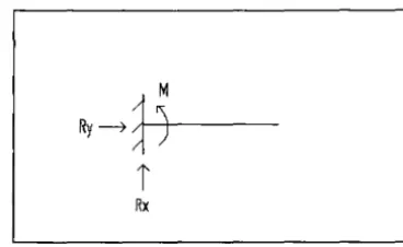
ii) Pin
Pin joint will prevent beam to move in y direction and x direction, but
allow beam to rotate. Therefore, no moment induce in this connection.
Ry
~"---4-t
[image:22.602.249.374.156.243.2]i
Rx [image:22.602.232.387.408.507.2]iii) Fixed end
Fixed end provide resistance in both x and y direction and rotation and
therefore able to persist moment.
Ry
~
1,f\)-l'
[image:23.604.215.399.207.320.2]Rx
Figure 1.3: Fixed End Support
1.2 Statement of Problem
Traditionally, analytical methods assumed beams to be supported at their
neutral axes. In these methods, eccentricity between beam support and beam neutral
axis is neglected. However, in most bending tests, beam specimens are supported at
the bottom face. This produces a vertical eccentricity between beam support and
beam neutral axis. Beams are also rested on wide support as oppose to point supports
Pour stops were introduced at the outer side of support in most of composite slab
test. For monolithically joint beam, column size effect beam stiffuess. What are the
The obje~tives of this project are
i) To determine the effect of eccentricity between beam support and
neutral axis to beam stiffness.
ii) To determine the effect of wide support as oppose to point support.
iii) To determine the effect of column size to beam stiffness.
1.4 Scope of Work
The scope of the work carried out in this study is limited to:
i) Linear stress analysis of hypothetical beams
ii) The models are 2-D Finite Element in plane stress condition, using
linear elastic materials
iii) Beam and column materials were made from concrete unless stated.
iv) Analysis are performed to examine
o The effect of vertical eccentricity at support.
o The effect of restraining the beam, ends at supports on the beam
stiffness.