Comparison Study in Various Controllers in
Single-Phase Inverters
Abstract-This paper explains the comparison of the controllers that suitable to be used in single phase inverter for studying purposes. This controller can easily been developed and tested using MATLAB/Simulink and implemented on the real time application. The controllers that have been developed are the Proportional Integration (PI)-dq controller, Proportional Resonant (PR) controller, and PR- Repetitive controller. The controller output will be connected to the pulse width modulation (PWM) generator to generate signal to the single phase inverters. All these controllers have been tested with the same load and simulation time.
Keywords- PI, PR, PWM
I. Introduction
Single-phase inverters are the converter which transform the DC input to the AC output. The inverters can be cascade to be 3-phase inverters, which is suitable for grid connection. The outputs for the single-phase inverter are the voltage output (VO) and the inductor current (IL) and by controlling the IL the inverter can be used as a grid connection. This paper is focused on the current control method which is used in the renewable energy application.
The current control for AC signal is not easy to implement due to time invariant current [1]. Other issues need to be consider are to maintain the stability and power quality [8] when it is connected to the renewable energy in achieves good grid connection. The best solution is to has an active feedback control with current feedback.
This feedback control can be model in many ways. As been reported, its used deadbeat control, sliding control, state feedback control, and dq transformation with the PI control as the classic approach to the control current [3]. As known, the outputs are the AC signal which is related to the frequency that not suitable for PI control if no changing has been made on the controller mode.
This paper analyses the single-phase inverter which is known as Voltage Source Inverter (VSI). This has been chosen because it is widely used and easy to develop. The controllers presented in this paper are the PI-dq controller, the PR controller and the PR-Repetitive controller. For the first controller it is based on Park transformation where it is used in three phase system but with some modification in order to obtain time-invariant variables [2] in single phase. This transformation creates the new imaginary signal [1] in the frame. It can be generated by the Phase Look Loop (PLL) application
The second controller is the PR control and is based on the resonant frequency of the inverter output, where it has 50Hz frequency. This controller gives an
advantage in performance at the fundamental frequency and ignore other frequency [3]. For the third controller it is based on the PR-Repetitive control that has ability to synthesize the error to minimize the low-order harmonic to the control signal [3,5]. This controller has ability to minimize the periodic error appear in the single phase PWM inverter [4].
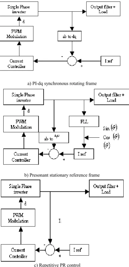
Fig. 1 shows the controller diagrams that have been used in this paper.
a) PI-dq synchronous rotating frame
b) Presonant stationary reference frame
[image:1.595.316.532.308.754.2]c) Repetitive PR control
Figure 1: Various controllers
Shamsul Aizam Zulkifli
*. Md Zarafi Ahmad
***Department of Electrical Engineering and Electronics, University of Liverpool, UK. Email:[email protected]
**
Jabatan Kejuruteraan Kuasa Elektrik, Universiti Tun Hussein Onn Malayia, Malaysia. Email: [email protected]Proceedings of 2010 IEEE Student Conference on Research and Development (SCOReD 2010), 13 - 14 Dec 2010, Putrajaya, Malaysia
II. System Description
A. LCL filter design
[image:2.595.62.262.165.256.2]The circuit diagram of the single-phase inverter is shown in Fig. 2 which consists of full bridge inverter, inductor (L), filter (C) and the load (R). The dead time effect and inevitable loss for every part have been ignored.
Figure 2: Single Phase Inverter
Table 1 shows the values that have been used in this study.
Symbol Description Value
L Inverter inductance 1.5mH
C Filter capacitance 10uF
[image:2.595.333.530.402.482.2]R Load Reistance 20
Table 1: Components
The area of interest in this paper is on the inductor current (IL). The transfer function of the inverter form inductor current to voltage source (IL/Vs) is given by,
R
SL
CRL
s
s
V
L
I
+
+
=
2
1
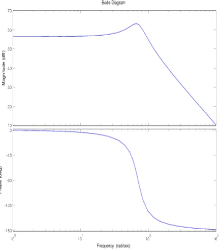
(1) [image:2.595.67.288.493.740.2]This transfer function generates the bode diagram shown in Fig.3. This bode diagram has a very high gain at the beginning and it will make the system to be unstable.
Figure 3: Single-Phase Inverter bode diagram
III. Controller Design
A. DQ single-phase current control.
The transformation to the dq frame requires the orthogonal components. The inverse transformation is shown in Eq. 2 .
⎥⎦
⎤
⎢⎣
⎡
⎥⎦
⎤
⎢⎣
⎡
⎥⎦
⎤
⎢⎣
⎡
−
=
β
α
θ
θ
θ
θ
)
cos(
)
sin(
)
sin(
)
cos(
q
d
⎥⎦
⎤
⎢⎣
⎡
⎥⎦
⎤
⎢⎣
⎡
⎥⎦
⎤
⎢⎣
⎡
−
=
q
d
)
cos(
)
sin(
)
sin(
)
cos(
θ
θ
θ
θ
β
α
(2)Both of these equations cannot be applied directly to the single-phase inverter because there only has one variable. This problem can be solved using a method proposed by [1] which know as fictions input current. As been explained in the previous section, this signal can be generated using the PLL. PLL generates three outputs which are angle (θ), cos(
ω
t)and sin(ω
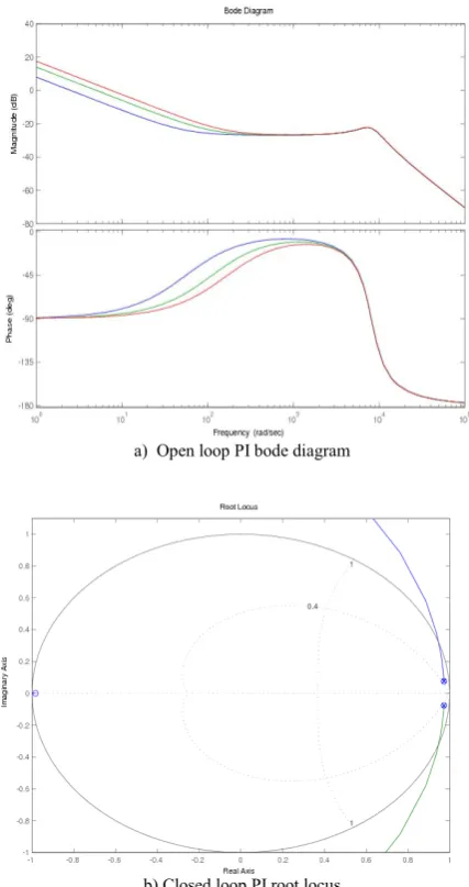
t). The last part is known as the fictions input current [1]. The control block for the dq transformation can be modelled by following equation, d I L pwmq V Ls V dt q di q I L pwmd V L s V dt d di pwm V o V dtL di L ω ω + − = − − = = + (3)This equation shows the control variables are DC quantities (d and q). The block diagram of the controller is shown in Fig.4 with the PI controller after the dq transformation. The PI controller is used because it gives no steady state current error in dc signal. The bode diagram and the root locus of the inverter with the PI controller is shown in Fig. 5.
[image:2.595.308.540.586.732.2]Proportional (Kp) Integration (Ki)
22 150
a) Open loop PI bode diagram
[image:3.595.65.279.77.481.2]b) Closed loop PI root locus
Figure 5: Bode diagram and root locus of PI control
The Kp value has been selected regarding to the closed loop root locus shown in Fig 5b where the target damping ratio is 0.4. The value has been selected because it will generate less then 5% overshoot on the step response of the system. In general the PI controller will be looked likes the low pass filter by reducing the magnitude/gain of the system while Ki value is based on the Fig 7 that gives bigger bandwidth.
Table 2: Kp and Ki value
For PI-dq bode diagram it shows that the controller is behaved like the low pass frequency filter. This not helps in reducing the THD on the overall performance. This controller is stable because all the poles are located inside the circle which is range from –1 to 1. This value is calculated in discrete time for easy observation.
B. P-Resonant controller
[image:3.595.307.534.298.445.2]The PR controller has been designed based on the frequency output of the IL. As known the output is 50Hz. The aim of this controller is to control the sinusoidal variable which has resonant frequency at 50Hz and in the same time reject others frequencies. Using only PI control alone which has pole at zero which gives infinite gain at zero frequency is not able to solve it. Due to this disadvantage, the PR controller is used where it has high gain at the resonant frequency [3]. Fig. 6 shows the PR controller block. This controller needs to have two controllers side which response to d and q components. The references values for d and q are 1 and 0. At the end of this control process the d and q can be sum together to generate the periodic signal that is used to generate the PWM signal to the inverter.
Figure 6 : PR controller block diagram
The transfer function of the PR controller is given by
2 2+ω
+ =
s s i K p K PR
C (4)
where ω = 2πf
The bode diagram for PR controller is shown in Fig. 7 where high gain is generated at the resonant frequency. The best gain value is selected when it has bigger bandwidth at the resonant frequency. This is because the bandwidth hopefully can cover the range of the resonant frequency between 48Hz to 52Hz. The values for Kp and K i are the same in Table 2. In the PR resonant control, the controller is based on the stationary rotating frame. The transformation between the single phase to the
αβ is given by
) sin(
) cos(
t t
ω β
ω α
= =
(5)
Figure 7: PR resonant bode diagram
Fig 7 shows that the PR resonant give high peak at the 50Hz.
C. PR-Repetitive Control
The repetitive control provides an alternative to minimize the measured error for the PWM generation [4]. It is able to give better performance for the steady state when the reference input signal is periodic. Repetitive control is able to modify the reference command by adding with the periodic compensation signal [5] to the input command to the controller. Generally the controller can be connected with PI,.PR or PID.
[image:4.595.306.534.166.475.2]In this paper the repetitive control is model based on the low past frequency combine with the repetition of the previous sample of the inductor current error. It calculates the correction component [5] which is shown in Fig. 8. This repetitive control affected to the odd frequency of the LC filter.
Figure 8: Repetitive –PR clock diagram
The value of the low pass filter is based on the resonant frequency. Because of the system is 50Hz output and the switching frequency is 10kHz the range of the frequency must base on the highest THD which is 31 where it equivalent to the 1500Hz and to the switching
frequency. In this paper the value that has been chosen is 10kHz where it is expected to eliminate most of the frequency. The repetition (1/ZN) is based on the sampling
of the signal where 200 points sampling has been used
.
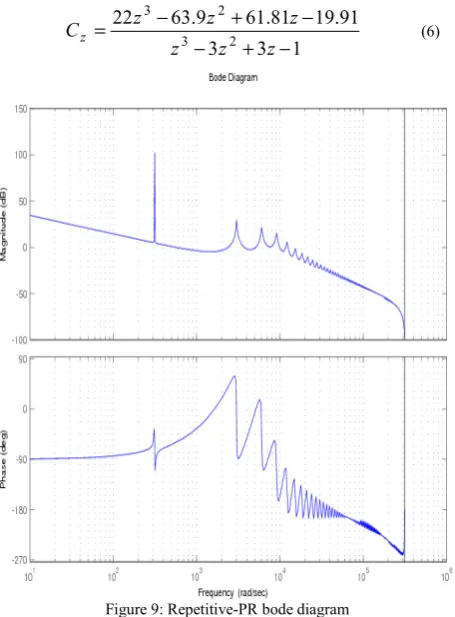
Fig 9, shows the repetitive response at odd harmonics of the system. By combine with PR controller, the controller can affects more accurately. The transfer function of the repetitive- PR control can be written in discrete time as,1 3 3
91 . 19 81 . 61 9 . 63 22
2 3
2 3
− + −
− +
− =
z z z
z z
z
Cz (6)
Figure 9: Repetitive-PR bode diagram
Fig 9 shows the repetitive response. It shows that the reputation is happen at odd harmonics. At his point it generated some gain regarding to the harmonic and it makes the harmonic to has zero steady state. This helps in reducing the THD of the system where it not be discussed in this paper.
IV. Simulation results
This section discussed the performance of each controller on the single-phase inverter. Each controller has been modelled in discrete time model and it ready to download in real time application. This paper will not discuss about real time implementation. The simulation measures three components, which are the (IL), (Vo) and the e (current error). All the controllers must have the ability to control the (IL) at the desired value which is 1A and to has minimum current error.
A. PI-dq control
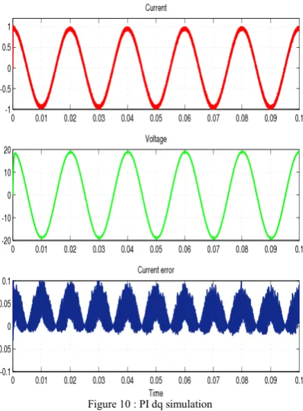
[image:4.595.58.285.567.681.2]Figure 10 : PI dq simulation
Fig. 10 shows the simulation result of the controller. The controller is able to control (IL) at the target value. For the current error graph the error is small which indicate that the Pi-dq controller can be used to minimize the difference between the reference signal and the measured signal while reducing the THD effect.
B. P-Resonant control
Figure 11: PR simulation
Fig.11 shows the simulation result for the PR controller. It shows the current is maintained at the 1A condition and the current error is limited at the range of the target. As known the PR controller is responded to the frequency and the current error will have sinusoidal affect. This indicates that the controller able to follows the resonant frequency. The advantage of this controller is the current shape is smoother and it is indicated the controller able to eliminate certain harmonics in the system.
[image:5.595.309.526.207.455.2]C. Repetitive-PR control
[image:5.595.63.285.495.744.2]Figure 12: Repetitive PR simulation
Fig. 12 shows the repetitive controller response on the single-phase inverter. In this result there has a delay on the generate output either on the IL and Vo. This is because in designing the controller the delay time/ repetition has been considered that will have more accurate responded to the system. In this result shows the target IL has been achieved but the main advantage of this controller is the current error is less compared to the previous controllers, which it range of –0.05A to 0.05A.
V. Conclusion
As a conclusion, this paper shows that single-phase inverter can be controlled by using different controller topologies such as PI-dq, PResonant and Repetitive PR with the current feedback loop. The Repetitive-PR gives better response in tracking the reference value that is allowed to generate better current at the output. It also gives better output and it is suitable to use in grid connection where it requires less THD.
VI. References
[1] U.A Miranda, M.Aredes, and L.G.B. Rolim, “A DQ Synchronous Reference Frame Control for Single Phase Converters”, IEEE 36th Power
[2] J.Salaet, S.Alepuz, A.Gilabert, and J.Bordonau, “Comparison between Two Methods of DQ Transformation for Single Phase Converters Control. Application to a 3-Level Boost Rectifier”, 35th Annual IEEE Power
Electronics Specialists Conference, 2004, Germany, vol.1, pp 214-220
[3] T. Hornik, “Control of Grid-Connnected DC-AC Power Converters for Distributed Power Generation Systems”, unpublished
[4] C.Rech, H. Pinheiro, H.A. Grundling, H.L.Hey, J.R.Pinheiro, “Analysis and Design of a Repetitive Predictive –PID Controller for PWM Inverters”, IEEE 32nd Annual Power Electronics Specialista
Conference, 2001, vol. 2, pp 986-991
[5] S.Duan, B.Liu, Y.Kang, J.Chen, “ Repetitive PD control strategy with inverse transfer function compensation for CVCF inverter”, Journal of Control Theory and Applications, vol.2, pp 121-125, 2004
[6] M.Jamil,S.M.Sharkh, M.Abusara, R.J. Boltryk, “Robust Repetitive Feedback Control of a Three Phase Grid Connected Inverter”, IET International Conference on Power Electronics, Machines and Drives 2010, pp 1-6
[7] Z.Xuesong, S.Daichun, M. Youjie, C. Deshu, “ Grid-connected control and simulation of single-phase two-level photovoltaic power generation system based on Repetitive control”, International Conference on Measuring Technology and Mechatronics Automation, 2010, pp 366-369