DYNAMIC CALIBRATION OF A GYROSCOPE USING A COMPOUND PENDULUM
I KTAN SEfC TEE, MOHAMMED AWAD, ABBAS DEHGHANI
School of Mechanical Engineeting, Un~versily ofLeeds Leeds, LS2 9JT, United Kingdom.
DAVID MOSER, SAEED ZAHEDI
Chas A Blatchford & Sons Lld, Lister Road, Basingslob, Elampshire, RG22 4AH, United Kingdom.
A novel method of dynamic calibration of a MEMS type gyroscope 1s presented in this paper. A compound pendulum installed w ~ t h a potentiometer as angular and angular speed reference was used to justify the scale factor and zero bias of a gyroscope Two gyroscopes, i.e. IDG300 and lDG500, were studied. It was found thal scale factor of
IDG300 matched with the manufacturer's datasheet while IDG5OO did not matched
1. Introduction
2. Methodology
2.1. Test Rig
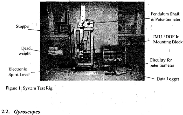
The test rig as shown in Figure 1 consists of a compound pendulum installed with a potentiometer as angular and angular speed transducer, a customized data logger, an TMU-5DOF and a stopper to initiate consistent release angle. A electronic spirit level is used to align the test rig platform horizontally.
Dead,
Electronic
-
Spir~t Level
Pendulum Shaft
& Potcntlometer
Mountlng Block
Clrcu~try for potentlometer
[image:2.525.121.437.268.467.2] [image:2.525.131.410.516.583.2]Data Logger
Figure 1 : System Test Rig
2.2. Gyroscopes
Two types of TMU-5DOF (SparkFun, Inc.) in the form of PCB-breakouts were used as shown in Figure 2. In this paper, gyroscopes (XR-axis, YR-axis), i.e. lDG300[12] and TDG500[13] (InvenSense, Tnc.) were studied and compared.
(a) (b) (c)
Figure 2 . (a). ADXL330 & lDG300, (a). ADXL335 & IDGSOO, (c). Axes Assignment
2.3. Simulation of A Second Order Damped System
Damping ratio, f and the natural frequency, w,, can be identified according to the method recommended by Ogata[lQ]. By using Laplace Transform, angular displacement, 0(t) can be solved as a function of time. The 1" and 2"* derivation would produce angular speed, 0(t) and angular acceleration,0(t). Simulation results would provide an approximation to the actual outputs in the potentiometer and the gyroscope.
2.4. Experiment Protocol
A differential op-amp was used to build the main circuitry for the potentiometer. Its output was fed into the data logger. Firstly, the potentiometer is calibrated as an electronic protractor over the angle range -40' to +40°. A regression equation of voltage versus angles was modeled. For each trials, the gyroscope was aligned in a specific plane such as Y-Z plane for XR axis or Z-X plane for YR axis. For convenient purpose, Z-X plane (YR axis) is explained throughout the paper. The pendulum was released at -40' specified by the stopper. Data logging starts from the release angle until the pendulum stops gradually. The same procedures were repeated for both gyroscopes in two planes.
3. Results
The potentiometer was statically calibrated and the average result of five trials were plotted as shown in Figure 3. Maximum standard deviation, 0.01 1178 was observed throughout the trials, indicating highly repeatability in the device.
Potent~omeler Volt vs Angle Max Sld = 0 011178
3 r - . . . . , - . l
0 l " " " ' l
40 30 20 10 0 10 20 30 40 Angle (Degree)
F~gure 3 Stat~c Cal~brat~on of Potentlometer
purpose, zero phase delay FIR low pass filter (ZPLP) was applied to pendulum angular speed. For the same release angle, TDGSOO exhibits inverse output and nearly half the amplitude as compared to IDG300.
Cmparlson of IDG300 & IDGSOO Pendulum LPLP Angular Speed
250
I
200 150
100
50
0
50 100
150
200
5 10 15 20 25
T~me (s)
(b)
Flgure 4 (a) Angular Speed - YR, (b) Angular Speed - Pendulum
The gyroscope in any axis is formulated as Eq. (1).
where V is gyroscope output in volt, Kc
is
scale factor (rn~/O/s) to be determined, w pis
pendulum angular speed in unit of '/s andZB,,is
average voltage of the gyroscope output.F~gure 5: (a). Gyro-YR scale factor in a trial, (b) Frequency Distribution
As shown Figure 5(a), scale factor, Kc was calculated and plotted. However, Kc
frequency distribution rl-iethod is proposed. The scale factor, I(, is located at the maximum frequency.
Calibrated scale factor, Kc of IDG3OO and IDGSOO were compared to the
manufacturer specification. TDG300 performs near to the given specification while IDG500 is less than half of the specification.
4. Results
A 2"* order damped system provides an approximation view of the angle, angular speed and angular acceleration of the pendulum, enhancing the confidence of the following analysis. Noises are generated due to 1'' derivative and 2"* derivative of the original signal. Improper design of a low-pass filter might attenuate or amplify the signal. It is a subjective procedure to adjust the cut-off frequency and stop frequency of a zero phase FIK low pass filter (ZPLP). Simulation results provitle a guide so that no underestimation nor overestimation of the signal. The range of the pendulum angular speed can be slightly increased by releasing at a bigger angle. Adding dead weights at the end of the pendulum would reduce the damping ratio, meaning that the pendulum will swing longer at slower damping rate. The pendulum is working on the gravity and it is not easy to acquire higher speed range without major mechanical design changes. It is most convenient and cheap for calibration of low range of angular speed such as for the application of gait analysis.
5. Conclusion
MEMS type gyroscope is popular in many applications. A simple dynamic calibration was proposed using a compound pendulum to identify its scale factor and zero bias. A 2"* order damped system was simulated and was providing the guide in the analysis. Two gyroscopes are calibrated and their difference with respect to the manufacturer specification were compared. It was found that IDG500 did not match the specification and a new scale factor was proposed.
Acknowledgments
References
D. H. Titterton and J. L. Weston, "Strapdown Inertial Navigation Technology," 2 ed: Institution of Engineering and Technology 2004. M. Brodie, A. Walmsley, and W. Page, "Fusion motion capture: a prototype system using inertial measurement units and GPS for the biomechanical analysis of ski racing," Sports Technology, vol. 1, pp.
17-28,2008.
J. Favre, B. M. Jolles, R. Aissaoui, apd K. Aminian, "Ambulatory measurement of 3D knee joint angle," Journal of Biomechanics, vol. 41, pp. 1029-1035 2008.
J. Rueterboriy, E. G. Spaich, B. Larsen, and 0 . K. Andersen, "Methods for gait event detection and ana'lysis in ambulatory systems,"
Medical Engineering, & Physics, vol. 32, pp. 545-552, 20 10.
W. T. Fong, S. K. Ong, and A. Y. C. Nee, "Methods for in-field user calibration of an ,inertial measurement unit without external equipment," Measurement Science and Technology, vol. 19, pp. 1-1 1 , 2008.
J. C. Lijtters, J. Schippe, P. H. Veltink, W. Olthuis, andlP. Bergveld, "Procedure for in-use calibration of triaxial accelerometers in medical applications," Sensors andqctuators A: Physical, vol. 68, pp. 221 -228, 1998.
1. Skog and P. Handel, "Calibration of a MEMS Jnertial Measurement Unit," in XVII llMEKO WORLD CONGRESS, Metrology for a . Sustainable DeveEopment, September, 17-22, 2006 Rio de Janeiro,
Brazil, 2006. I
F. Ferraris, U. Grimaldi, and M. Parvis, "Procedure for Effortless Tn- Field Calibration of Three-Axis Rate Gyros and Accelerometers,"
Sensors and Materials, vol. 7, pp. 3 1 1-330, 1995.
J. C. Hung, J. R. Thacher, and H. V. White, "Calibration of accelerometer triad of an IMU with drifting Z -accelerometer bias,"
Aerospace and Electronics Conference, 1989. NAECON 1989., Proceedings of the IEEE 1989Naliona1, vol. 1, pp. 153
-
158, 1989. A. Kim and M. IF. Golnaraghi, "Initial calibration of an inertial measurement unit using an optical position tracking system," inPosition Location and Navigation Symposium, 2004. PLANS 2004:
IEEE, 2004, pp. 96
-
101K. R. Britting, Inertial Navigation Systems Analysis: Wiley-
Interscience, 1971.
LDG300, "Integrated Dual-Axis Gyro," JnvenSense, Inc., 2006. IDG-500, "Integrated Dual-Axis Gyro," InvenSense, Inc., 2008. K. Ogata, System Dynamic, Fourth ed. New Jersey: Pearson Prentice
Hall, 2004.