THE APPLICATION OF IR AND PIC MICROCONTROLLER IN
EXPRESS BUS ARRIVAL AND IDENTITY NOTIFICATION SYSTEM
Ayob Johari, Chong .Wah .Kiat, Danial. Md. Nor, Mohd. Helmy. Abd .Wahab, Nik Shahidah Afifi Mohd Taujuddin, Mohd Erdi Ayob
Faculty of Electrical and Electronic Engineering Universiti Tun Hussein Onn Malaysia Parit Raja, Batu Pahat, Johor. MALAYSIA
Express Bus Arrival and Identity Notification System (EBAINS) is designed to create the convenience for the awaiting passenger in any express bus terminal. This system can provide hassle-free from going to the platform or counter to check the arrival of any particular bus. With this system, each bus has its own arrival indicator at the waiting lobby to indicate its arrival. Transmitters and receivers are installed at buses and platforms to facilitate the detection of bus arrivals. LCD that displays the number of the respective bus is utilized as the arrival indicator. Technically, infrared transceiver was used as transceiver in which the IR transmitter is installed on the bus whereas the IR receiver is installed at the platform. Signal will be encoded before being transmitted. With encoding, the bus is virtually given an identity as each bus is assigned a unique digital code. Besides, IR receiver at the platforms is common to every transmitter on the buses which implies that no matter which platform a bus stops, it can be detected. At the receiver, the received infrared signal is decoded. Decoded signal is then passed to PIC microcontroller chip which determines the number to be displayed accordingly. Basically, the display system for flight departure and arrival information of flight information display system (FIDS) is adapted in this project. Although the function of this system is not as complete as FIDS, it is cheaper and sufficient to solve this problem and satisfy the needs of a bus terminal. The implementation of EBAINS (Express Bus Arrival and Identity Notification System) will surely create a more comfortable express-bus-waiting experience.
Keywords: LCD, encoding, decoding, IR, transceiver, PIC microcontroller.
.
1. INTRODUCTION
In bus station, when an express bus ticket is bought, the information on the arrival platform, time and number of the bus will be given. When the arrival of that particular bus is not punctual we would have to wait at the platform or the waiting lobby. However, waiting at the lobby would require us to constantly check at the platform or counter the arrival of the bus. Due to this inconvenience, this project is oriented towards creating an express bus arrival and identity notification system. Obviously, this system is designed to create the convenience that passenger awaiting arriving express bus can avoid the hassle of going to the platform or counter to check the arrival of that particular bus. With this system, each bus has its own arrival indicator at the waiting lobby to indicate its arrival. Transmitters and receivers are installed at buses and platforms to facilitate the detection of bus arrivals. LCD display that displays the number of the respective bus is utilized as the arrival indicator.
2. PROBLEM
The unpunctuality of the arrival of express bus is a common phenomenon which often poses an inconvenience to the awaiting passenger. Passenger waiting at the lobby has to constantly check the arrival of the bus at the platform or ticket counter. Creating a system that can notify the passengers the arrival of the bus would certainly solve this problem. System that performs the similar function was studied before deciding on the system to be created. Flight Information Display System (FIDS) is a system that controls all passenger and airport information displays throughout an airport site. This primarily consists of displays for flight departure and arrival information, baggage reclaim information, check-in displays and gate displays throughout a terminal, terminal approach displays and other displays for internal airport users. The function of FIDS that is of concern is the displays for flight departure and arrival information. The display technology used can vary depending on the application and project budget and may include CRT monitors, plasma monitors, LCD display and LED display. The flight information display system has an automated interactive voice response system that provides up-to-date information for all scheduled flights arriving and departing airport. The system is updated automatically by a data feed that is provided by the actual radar data of the aircraft. Once the aircraft becomes airborne it is updated immediately. The only time an update must be made manually is when there is a delay on the ground. The display system for flight departure and arrival information of flight information display system (FIDS) is adapted to create the system of this project. With the adaptation, there will be LCD in the system of this project that displays the number plate of the respective bus upon its arrival. Transmitters and receivers will be installed at buses and platforms to facilitate the detection of the bus arrival in which the former is analogous to the radar of the aircraft and the latter is analogous to the receiver at the airport. Although the function of this system is not as complete as FIDS, it is cheaper and sufficient to solve this problem and satisfy the needs of a bus station.
2.1 Objectives
This project has the following objectives:
i) Study and understand the function of microcontroller and other important components of the system.
ii) To bring together hardware skills, electronics knowledge, with some software programming in building the system
iii) Design and construct an Express Bus Arrival and Identity Notification System by using suitable microcontroller.
2.2 Scope
a) Initial studies on PIC programming language which includes basic command and examples of PIC program were carried out. There were also some other software studied such as MPLAB.
b) Develop programs that are needed to perform certain functions in this system such as LED display.
3. INFRARED
Infrared transmission is for short distance communications which is up to several meters and limited to line-of-sight In this project, a system is to be designed to indicate the arrival and departure of bus. If RF transmission is utilized, the bus arrival and departure indication will not be precise as the RF signal will be detected from far distance whereas when infrared transmission is utilized, the indication of bus arrival will be activated only when the bus is in sight. Infrared signal is immune to most common interference. Hence, utilization of infrared signal is very suitable for bus station which environment contains different types of man-made and common interference such as cell phones and radio.
Infrared transmission allows multiple transmitters to be used in close proximity without interfering each other when operating. This makes infrared transmission a suitable mean of transmission for this project as in practical implementation; transmitter will be installed on buses that park closely to each other. Moreover, the receivers will be built in such a way that it is common to every transmitter on the bus. In practical implementation, these receivers will be installed on bus parking bay which is close to each other. With infrared transmission, signal intended for a particular receiver will not be detected for other similar receiver. In contrast, the utilization of RF transmission will cause signal intended for a particular receiver to be detected by another receiver as well. One of the limitations of infrared transmission which is the deterioration of range dramatically by sunlight is not a major issue in this project as the parking bays of bus station is roofed from sunlight.
4. METHODOLOGY
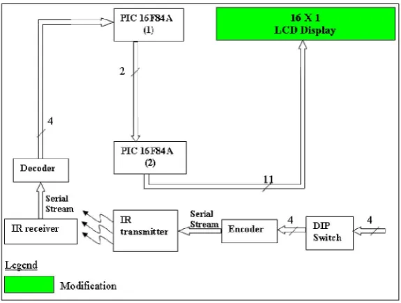
The system of this project is generally illustrated in the block diagrams in Figure 3.1. This system is mainly comprised of switch, encoder, decoder, IR transceiver, PIC16F84A, decade counter, 17 X 7 dot matrix LED display and common cathode 7-segment LED display.
4.1 Switch
To determine the pattern of the parallel 4 bits binary data to be passed to the encoder.
4.2 Encoder
Encoder functions as to encode the parallel digital signal into serial stream. HT12E is utilized as encoder in which 12 lines of information are serially sent upon receipt of a transmit enable (TE) signal. 8 lines of the 12 lines determine the address code while the other 4 lines is the data code.
4.3 IR transceiver
Figure 4.1 : Block Diagram of System
4.4 Decoder
To receive the serial stream and interprets 8 of the digits as address code. The remaining serial information is interpreted as 4 bits of data code.
4.5 PIC16F84A
PIC16F84A(1) accommodate 4 lines of input from the decoder as insufficiency of ports will occur if 1 PIC is utilized for reception of 4 lines input of decoder and display of bus number (11 lines). PIC16F84A (2) determines the numbers to be displayed.
4.6 16 X 1 LCD display
16 X 1 LCD display is used to display the bus number accordingly.
4.7 IR Receiver Circuitry
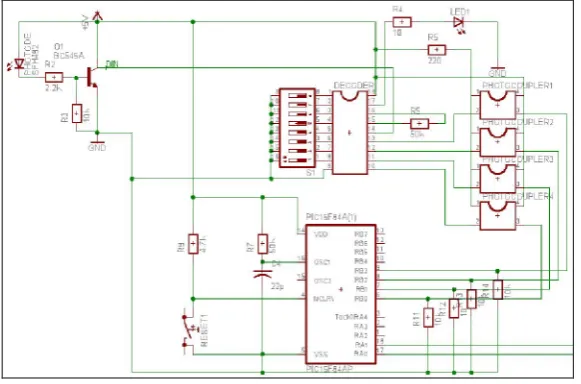
is much bigger than the input signal at the base. The amplified signal at collector of NPN transistor is fed to DIN of decoder. This a 212 decoder is paired with 212 encoders. The received serial addresses and data from the encoders at the NPN collector are fed to DIN of decoder. The decoders receive data that are transmitted by an encoder and interpret the first N bits of code period as addresses and the last 12_N bits as data, where N is the address code number. A signal on the DIN pin activates the oscillator which in turn decodes the incoming address and data. The decoders will then check the received address three times continuously. If the received address codes all match the contents of the decoders local address, the 12_N bits of data are decoded to activate the output pins and the VT pin is set high to indicate a valid transmission. This will last unless the address code is incorrect or no signal is received. LED1 is connected to VT for valid transmission indication. The HT12D provides 4 latch type data pins whose data remain unchanged until new data are received. The signals on these 4 data pins are fed to 4 photocouplers before RB0-RB3 of PIC16F84A (1). The photocouplers provides signal isolation for circuitry connected in between them. Besides, they are connected in such a way that signals from data pins are inverted before being fed to RB0-RB3 of PIC16F84A (1). Signal arrived at RB0-RB3 are then converted to 2 lines of output at RA0 and RA1. These 2 lines of output is fed to PIC16F84A(2) in which PIC16F84A(2) is to facilitate the displaying of bus number.
Figure 4.2: IR Receiver Circuitry
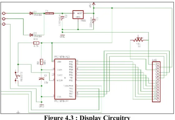
4.8 Display circuitry
Figure 4.3 : Display Circuitry
4.9 Source Code Implementation.
In this project, two programs were written for both PIC16F84A to perform the desired functions. These programs were written with reference to their respective flow chart
4.10 Header of the program
First of all, the program of this project is started with the definition of the microcontroller with its configurations, the declaration of variables and the origin of program. These configurations include the types of oscillator that has been used and the watchdog timer setting. Figure 3.4 shows the header of program for PIC16F84A(1) while Figure 3.5 shows the header of program for PIC16F84A(2).
Figure 4.4: Header of PIC16F84A (1) program
Figure 4.5: Header of PIC16F84A(2) program
4.11 Main Program of PIC16F84A(1)
btfss command. Code_1 performs the function to test port RB0. If RB0 is tested HIGH, Port A is set accordingly. Otherwise, subsequent input port B is tested using the similar method.
Figure 4.6: Integral Part of PIC16F84A (1) Main Program
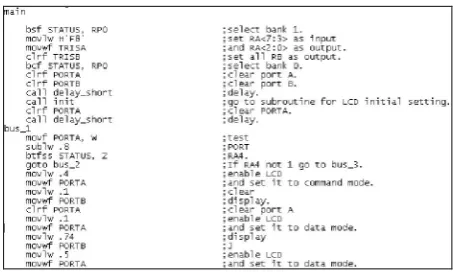
4.12 Main Program of PIC16F84A(2)
The integral part of PIC16F84A (2) main program is as shown in Figure 3.7. Port RA3 to RA7 is set as input while all port B is set as output. These ports are tested one by one by using sublw and btfss command. Bus_1 performs the function to test port RA4. If RA4 is tested HIGH, Port B is set accordingly to form the ASCII code for the character to be displayed. Otherwise, subsequent input port B is tested using the similar method. Program in Figure 3.7 shows that ASCII code of decimal 74 is set at port B for the display of J character. Generally, there are three steps in setting port B for the display of a character. Initially, RA0 is set HIGH so that HIGH signal can be fed to Rs of LCD to set it to data mode. Then, ASCII code is set at port B. Lastly, RA2 is set HIGH so that HIGH signal is fed to Enable pin to enable the LCD in order for J to be displayed.
Figure 4.7: Integral Part of PIC16F84A(2) Main Program
5.0 RESULTS AND DISCUSSIONS
[image:7.595.201.428.443.579.2]communication and allow multiple transmitters to be used in proximity without interfering each other.
However, initial plan was to use dot matrix LED display and 7-segment LED display for bus number display purpose. To display an alphabet using dot matrix LED display and number using 7-segment LED display, synchronization of timing between the clock of decade counter (4017) and PIC is required. Moreover, number and alphabet are displayed using two different PIC which require the synchronization of clocking between both PIC for proper display of bus number. Figure 5.3 illustrates the circuit configuration for dot matrix LED display which explains the need of accurate clocking synchronization between PIC and decade counter.
[image:8.595.93.461.329.452.2]Due to time constraint, LCD display is utilized instead. LCD display does not require the tedious process of tuning the synchronization of clock timing between decade counter and PIC as displaying through LCD is on ASCII code basis. The disadvantages of using LCD display is that it is not easily perceptible in comparison to LED display as it is passive display technology which means they do not emit light. However, if implemented practically, this shortcoming of using LCD display can be overcome by using a bigger size.
Figure 5.1: Transmitter board board
Figure 5.2: Receiver
.
[image:8.595.231.401.510.666.2]5.2 Probed signal
Following is the signal probed at important points of the circuit which prove and explain the functionality of this circuit.
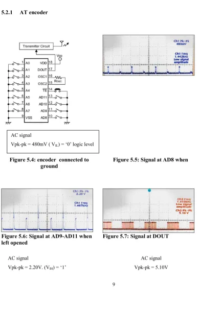
[image:9.595.92.484.170.776.2]5.2.1 AT encoder
Figure 5.4: encoder connected to ground
Figure 5.5: Signal at AD8 when
Figure 5.6: Signal at AD9-AD11 when left opened
Figure 5.7: Signal at DOUT
AC signal
5.2.2 At decoder
Figure 5.8: decoder Figure 5.9: Signal at D9-D11
5.2.2 Overall Comment
The above results prove the:
i) Successful transmission of data through IR transceiver :
[image:10.595.93.540.114.263.2]a. Signals at DOUT of encoder and DIN of decoder are of similar pattern. However there is an increment of 0.7Vpk-pk at DIN which is due to signal amplification by the transistor shown in Figure 4.10
b. D8-D11 at encoder = 0111 D8-D11 at decoder = 0111
ii) Successful encoding and decoding of data : D8-D11 at encoder = 0111
D8-D11 at decoder = 0111
5.3 The Ideal Angle and Distance For Effective Signal Transmission
Experiment through run test was done to measure the maximum distance and angle of signal could reach. During the run test, the IR receiver is fixed at a place, while the IR transmitter is fixed at a distance of 20 cm until 1m and different angle from the IR receiver. Result for this run test is as shown in Table 4.1
Table 5.1: The effective angle and distance for every 20cm increment
Distance (cm)
Vertica l angel (degree )
Horizont al angle (degree)
Transmissi on status
20 50 60 OK
40 40 50 OK
60 30 40 OK
80 20 30 OK
100 10 30 OK
120 - - No signal
DC signal
Vpk-pk = 5.28(VOH) = ‘1’ logic
[image:10.595.208.424.568.706.2]6.0 CONCLUSION AND RECOMMENDATION
On overall, the objectives of the project were achieved. The complex circuit has been reduced using the application of PIC microcontroller. It has been proven that this microcontroller able to perform the controlling task based on the instruction given. It can be used to replace complex digital and analogue circuit.
The main objective of this project to detect the express bus arrival and display its number plate is achieved. However it has drawback on its display part. The transmission of signal using IR transceiver is a success with maximum operating range and beam width is approximately 1m and 30 degree which serves its intent to facilitate line-of-sight communication and allow multiple transmitters to be used in proximity without interfering each other. LCD display is used instead in which it is not easily perceptible in comparison to LED display.
6.1 Recommendations
Improvement can be made to enhance this system. Encoder and decoder with greater number of data bits and PIC with greater number of ports can be used to increase the amount of bus that can be supported by the system. Besides, integration of this system with database will surely augment the intelligence of this system; departure time and destination of express bus can be displayed as well. Lastly, the utilization of LED display will prompt a clearer display of information.
REFERENCES
[1] Predko, Myke (1998). “Programming and Customizing The PIC Microcontroller.” McGraw Hill.
[2] S.O.Kasap (1991). “Optoelectronics and Photonics Principles and Practices.” Prentice Hall. [3] 16F84A 18-pin Enhanced FLASH/EEPROM 8-bit microcontroller datasheet
[4] A. R Jha (2000). “Infrared Technology.” Willey-Interscience
[5] Sid Katzen (2000). “The Quintessential PIC Microcontroller.” Springer [6] http://cnx.rice.edu/content/m11655/latest/