Numerical Investigation of Turning Diffuser Performance by Varying
Geometric and Operating Parameters
Normayati Nordin
1, a, Vijay R. Raghavan
2, Safiah Othman
1and Zainal Ambri Abdul Karim
31Faculty of Mechanical and Manufacturing Engineering, Universiti Tun Hussein Onn Malaysia, Parit Raja, 86400 Batu Pahat, Johor, Malaysia
2OYL R&D Center Sdn Bhd, Selangor, Malaysia
3Department of Mechanical Engineering, Universiti Teknologi PETRONAS, Tronoh, Perak, Malaysia
Keywords: Pressure Recovery, Flow Uniformity, CFD, Turning Diffuser, Geometric and Operating Parameters
Abstract: This paper presents a numerical investigation of pressure recovery and flow uniformity in turning diffusers with 90o angle of turn by varying geometric and operating parameters. The geometric and operating parameters considered in this study are area ratio (AR= 1.6, 2.0 and 3.0) and
inflow Reynolds number (Rein=23, 2.653E+04, 7.959E+04, 1.592E+05 and 2.123E+05). Three
turbulence models, i.e. the standard k- turbulence model (std k-), the shear stress transport model (SST-k-) and the Reynolds stress model (RSM) were assessed in terms of their applicability to simulate the actual cases. The standard k- turbulence model appeared as the best validated model, with the percentage of deviation to the experimental being the least recorded. Results show that the outlet pressure recovery of a turning diffuser at specified Rein improves approximately 32% by
varying the AR from 1.6 to 3.0. Whereas, by varying the Rein from 2.653E+04 to 2.123E+05, the
outlet pressure recovery at specified AR turning diffuser improves of approximately 24%. The flow uniformity is considerably distorted with the increase of AR and Rein. Therefore, there should be a
compromise between achieving the maximum pressure recovery and the maximum possible flow
uniformity. The present work proposes the turning diffuser with AR=1.6 operated at Rein=2.653E+04
as the optimum set of parameters, producing pressure recovery of Cp=0.320 and flow uniformity of
u=1.62, with minimal flow separation occurring in the system.
Introduction
There are various types of diffusers which are commonly classified by their geometries and applications. Study of the geometric and operating parameters that affect on the diffuser performance has been of fundamental interest to researchers in the area of fluid mechanics since decades and it continues to grow [1]-[12]. Basically, the performance of a diffuser is evaluated in terms of its pressure recovery and flow uniformity. The maximum possible pressure recovery and flow uniformity can be obtained by setting the geometric and operating parameters optimally. In the present work, a turning diffuser with 90o angle of turn is considered. Basically, the inner wall is subjected to the curvature induced effects, where under a strong adverse pressure gradient, the boundary layer on the inner wall (i.e.convex region) is likely to separate, and the core flow tends to deflect to the outer wall (i.e. concave region) [1], [7]. This eventually leads to the formation of pressure-driven secondary flows that thicken the inner wall boundary layer and makes it susceptible to flow separation.
Computational fluid dynamics (CFD) as a tool has been widely employed by scientists and engineers in flow studies. The total dependance on experimental methods can be reduced by implementing the CFD techniques. There is basically a challenge in assigning the best model to
represent the actual case particularly when involving a complex flow [10]. Bourgeois et al. [10] have considered four turbulence models to predict the mean flow fields of a fish tail-shape diffuser that was incorporated in the aero engine centrifugal compressor. The models analysed were the k- turbulence model, the shear stress transport (SST) model, a proposed modification SST model denoted as the SST-reattachment modification (SST-RM) and the Speziale, Sarkar and Gatski Reynolds stress model (RSM-SSG). The RSM-SSG and SST models gave more accurate predictions of mean flow fields as compared to the k- turbulence model and the shear stress transport (SST) model.
The standard k- turbulence is the model introduced by Jones and Launder [11], which has been
used widely in industry. This model has managed to predict the onset flow separation accurately [3]. There are several successful studies for predicting the flow within a diffuser, which have employed k-
turbulence model [3], [8], [12]. The k- and k- turbulence models have been used by Ibrahim et al. [13] to investigate the effect of curvature and cross-sectional transitioning on the performance of S-shape diffuser. Both models have shown good agreement with the experimental data. However, the shape of the core flow obtained by the k- model has provided slighly better accuracy.
The current work uses the commercial CFD code FLUENT to model and simulate the performance of turning diffusers. Three potential turbulence models, i.e. the standard k- turbulence model (std k-), the shear stress transport model (SST k-) and the Reynolds stress model (RSM), are assessed and validated with the experimental data. The best validated model is used to further investigate the effect of varying geometric and operating parameters on the pressure recovery and flow uniformity of turning diffusers. The optimum geometric and operating parameters setting that leads to a compromise between pressure recovery and flow uniformity is suggested.
Geometric and Operating Parameters
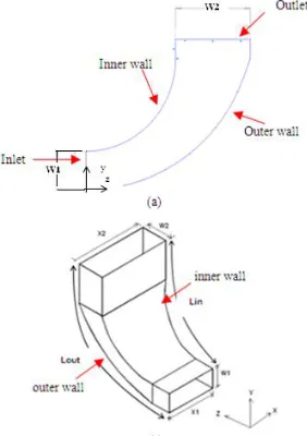
The turning diffuser with 90o angle of turn is considered in this study. The diffuser inlet is 130 mm x 50 mm. As shown in Figure 1 both inner and centerline are quadrant of a circle. The outer wall is shaped such that equal area distributions are established for the inner wall and outer wall relative to the centreline. In this study, the geometric and operating parameters considered are area ratio (i.e.
AR=1.6, 2.0 and 3.0) and inflow Reynolds number (i.e. Rein=23, 2.653E+04, 7.959E+04,1.592E+05
and 2.123E+05).
Fig. 1 - (a) 2-D geometric layout of turning diffuser with 90o angle of turn (b) 3-D geometric layout of turning turning diffuser with 90o angle of turn
Performance Parameters and Governing Equations
The performance of turning diffuser is evaluated in terms of outlet pressure recovery coefficient (Cp)
and flow uniformity index (u). Cp represents the kinetic energy that has been converted into pressure
[image:2.595.223.364.491.691.2]2 ) ( 2 inlet inlet outlet V P P Cp
(1)
where,
Poutlet = average static pressure at diffuser outlet (Pa)
Pinlet = average static pressure at diffuser inlet (Pa) = air density (kg/m3)
Vinlet = inlet air velocity (m/s)
The flow uniformity is evaluated by calculating standard deviations (u) of outlet velocity. The
least of absolute deviation corresponds to the greatest uniformity of flow. Standard deviation (u) can
be expressed as,
2 1 ) ( 1 1
N i ave iu V V
N
(2)
where,
N= number of measurement points Vi = local velocity (m/s)
Vave = average velocity (m/s)
Besides that, the performance of turning diffuser can also be described by means of the overall loss coefficient (K),
K1Cp (3)
The flow is assumed to be incompressible, two-dimensional (y and z direction), fully-developed, steady state and isothermal. The gravitational effect is negligible. By applying the boundary conditions, Reynolds Average Navier Stokes (RANS) equations as following are solved,
Continuity equation:
0
z w y v
(4)
y- momentum equation:
My S z w v y v z v y v y P z v w y v
v
1 ( 2) ( )
2 2
2 2
(5)
z- momentum equation:
Mz S z w y w v z w y w z P z w w y w
v
1 ( ) ( 2)
2 2 2 2 (6) ComputationalDetails
The 2-D geometric model, as shown in Figure 1, is created in GAMBIT 2.4.6. Triangular meshing shape with a pave scheme is generated, forming total of 3599 cells. The commercial CFD code FLUENT 6.3.26 is used to simulate the model by adopting the SIMPLE algorithm solution. Pressure is discretised using second order scheme, whereas momentum and the rest of turbulence parameters are discretised by means of second order upwind scheme. A convergence criterion of 1E-05 is applied. The description of applied boundary and operating conditions is in Table 1.
Validation between Computational and Experimental Works
The applicability of three turbulence models, i.e. the std k- model, the SST k- model and the RSM model, to simulate the flow in turning diffuser is assessed. The mean and outlet velocity profile obtained numerically is validated with the experimental results. A turning diffuser with AR = 2.0 operated at low inflow Reynolds number, Rein=23 is considered for the validation. Despite a slight
difference to the experimental, all the models manage to simulate meaningful and explainable outlet velocity profiles (see Figure 2(a)). The outlet velocity is fairly distributed when the Rein is low.
However, there is insufficient pressure energy built up, thus the diffuser makes a great loss of approximately K=5.9. By introducing the high Rein of 2.653E+05 the loss reduces to 0.6.
depicted in Table 2, the percentage of deviation between numerical and experimental result is considerably large up to 34.1%. This is mainly due to the assumption made in the simulation which the inlet velocity is fully developed and uniform. However, this is not the case in the actual as the inlet velocity is fairly distorted due to the imperfect duct joint and the abrupt change of the inlet cross-section introduced as shown in Figure 3(a) and (b).
Table 1- Description of boundary and operating conditions
Inlet:
i Type of boundary Velocity-inlet
ii Inflow Reynolds number (Rein) 23 (0.004 m/s)
2.653E+04 (5 m/s) 7.959E+04 (15 m/s) 1.592E+05 (30 m/s) 2.123E+05 (40 m/s)
iii Inlet turbulence intensity, Iin (%) 16(Rein)
-1/8
iv Inlet hydraulic diameter, Dhin (m) 4Ain/Pin
Outlet:
i Type of boundary Pressure-inlet
ii Pressure specified 0 Pa gage pressure
iii Outlet turbulence intensity, Iout (%) 16(Reout)-1/8
iv Outlet hydraulic diameter, Dhout (m) 4Aout/Pout
Inner and outer wall:
i Type of boundary Smooth wall
ii Shear condition No- slip
Working fluid properties:
i ii
Working fluid
Temperature (oC)
Air 30
iii Density of working fluid (kg/m3) 1.164
[image:4.595.113.485.452.606.2]iv Viscosity of working fluid (kg/ms) 1.872E-05
Table 2- Comparison of mean outlet velocity for numerical and experimental works
CFD models
Mean outlet velocity (x10-3 m/s)
Computational Experimental Deviation (%)
Std k-ε 1.642
2.464
33.3
SST k-
RSM
1.640 1.624
33.4 34.1
(a) (b)
Fig. 2 (a) Comparison between outlet velocity profiles obtained numerically, i.e. using std k- ε, SST k-, and RSM models, with the experimental (b)- Outlet velocity profile obtained numerically using
std k- ε, SST k-, and RSM models in the case of high Rein
(a) (b)
[image:4.595.125.468.662.764.2]Improvement to the existing rig is thus proposed. The settling chamber with multiple screens arrangement and contraction cone will be installed before the diffuser inlet. This is to ensure the flow entering diffuser is fully developed and uniformly distributed. The contraction cone is designed based on the fifth order polynomial proposed by Bell and Mehta [14]. In the present work, the std k-ε turbulence model appears as the best validated model since the percentage of deviation to the experimental is the least recorded. In fact, this model has been proven adequate to represent the flow phenomenon in diffusers [3], [8], [10], [12]. Therefore, further simulations to predict the effects of geometric and operating parameters on the pressure recovery and flow uniformity of turning diffuser are performed using this model. The closure coefficients applied are Cμ=0.09, Cε1=1.44, Cε2=1.92, k=1.0 and ε=1.3.
Effect of Area Ratio (AR) and Inflow Reynolds Number (Rein) on Pressure Recovery (Cp)
Results
Table 3 shows the effect of varying AR and Rein on the outlet pressure recovery. Negative pressure
recovery is obtained when the low inflow Reynolds number, Rein=23 is applied. Due to insufficient
[image:5.595.66.526.335.429.2]pressure energy provided at the inlet, the system fails to sustain the flow to get a good recovery.
Table 3. Effect of varying area ratio (AR) and inflow Reynolds number (Rein) on outlet pressure recovery (Cp)
Area ratio (AR)
Outlet pressure recovery (Cp) Maximum
percentage of improvement (%) Rein=23 Rein =2.653E+04 Rein =7.959E+04 Rein =1.592E+05 Rein =2.123E+05
1.6 -5.744 0.320 0.368 0.392 0.403 26
2.0 -4.861 0.373 0.425 0.448 0.458 23
3.0 -4.023 0.422 0.492 0.515 0.524 24
Maximum percentage of improvement (%)
32 34 31 30
According to Wang et al. [9], the high inflow Reynolds number, Rein>500 should be used in order
to improve the recovery. Hence, the effect of high Rein on pressure recovery is emphasized more in
this work. Results show that by varying the Rein from 2.653E+04 to 2.123E+05, the outlet pressure
recovery for a specified AR turning diffuser improves approximately 24% on average. On the other hand, by varying the AR of turning diffuser from 1.6 to 3.0 at specified Rein the outlet pressure
recovery improves approximately 32% on average. Therefore, the effect of varying AR is more significant than the effect of varying Rein on the improvement of pressure recovery.
Effect of Area Ratio (AR) and Inflow Reynolds Number (Rein) on Flow Uniformity (u) Results
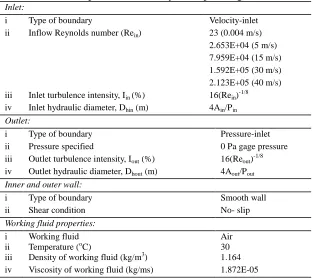
As depicted in Table 4, the flow uniformity is extremely distorted with the increase of Rein from
2.653E+04 to 2.123E+05 at specified AR maximum up to 669%. On the other hand, the increase of AR from 1.6 to 3.0 at specified Rein disrupts the flow maximum only up to 15%. The flow uniformity
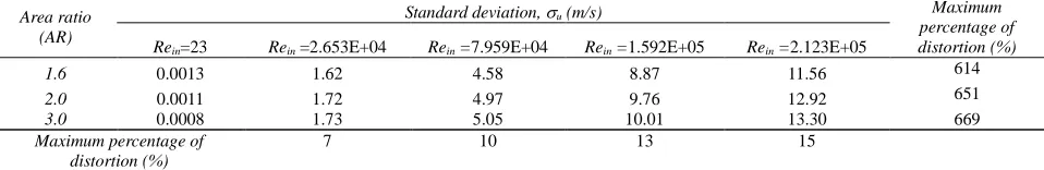
at the turning diffuser outlet is considerably distorted, with the core flow deflected much to the outer
wall section when the large AR and high Rein is introduced (see Figure 8). Under a strong adverse
[image:5.595.59.538.698.776.2]pressure gradient, the boundary layer on the inner wall is thickened. Ultimately, the flow detachment occurs because of the fluid particles at the near inner wall region experience a greater retarding shearing force than the pressure pushing it. Overall, the increase of AR less affects the flow uniformity, as compared to the increase of Rein.
Table 4. Effect of varying area ratio (AR) and inflow Reynolds number (Rein) on flow uniformity(u)
Area ratio (AR)
Standard deviation, u (m/s) Maximum
percentage of distortion (%) Rein=23 Rein =2.653E+04 Rein =7.959E+04 Rein =1.592E+05 Rein =2.123E+05
1.6 0.0013 1.62 4.58 8.87 11.56 614
2.0 0.0011 1.72 4.97 9.76 12.92 651
3.0 0.0008 1.73 5.05 10.01 13.30 669
Maximum percentage of distortion (%)
(a) (b)
[image:6.595.56.510.67.359.2](c)
Fig. 8- The effect of high Rein on the outlet velocity profile of turning diffuser (a) AR=1.6, (b)
AR=2.0 and (c) AR=3.0
Compromise between Pressure Recovery and Flow Uniformity
The maximum outlet pressure recovery could be obtained by adopting the large AR turning diffuser, that is operated at high Rein. However, this measure particularly whereby increasing the Rein could
substantially distort the flow uniformity. A compromise between the best produced pressure recovery and the maximum possible flow uniformity is always on the top when designing a turning diffuser. Figure 9 shows that by maximizing the area ratio from 1.6 to 3.0, considerable flow separation occurs on the inner wall, particularly when the AR=3.0 is considered, producing the maximum non-uniformity of u=13.3. Despite the best recovery provided, the turning diffuser with AR=3.0,
operated at Rein= 2.123E+05 cannot not be considered as the optimum design due to major flow
disruption. Basically, the flow separation is undesirable in many fluid systems as it would increase the pressure drag, decrease the core flow area, reduce the handling stability, generate noise and enhance the structural vibration [7]. For a turning diffuser with AR=2.0, the flow separation starts to occur even when it is operated at Rein= 2.653E+04.
As shown in Figure 9 (a), a turning diffuser with minimum area ratio of 1.6 seems to have relatively minor flow separation with the least non-uniformity of u=1.62 recorded when it is
operated at Rein=2.653E+04. The outlet pressure recovery provided by this system is Cp=0.320.
Guohui and Saffa [3] have proposed that the optimum area ratio for a straight pyramidal diffuser was from 1.73 to 1.95, giving the maximum pressure recovery of Cp=0.480, with no flow separation
occurred. In the present work, the maximum possible pressure recovery of Cp=0.403, with minimal
flow separation could be provided by turning diffuser of AR=1.6, operated at Rein= 2.123E+05.
However, the flow uniformity is highly distorted, u=11.56.
Hence, a turning diffuser with AR=1.6 operated at Rein=2.653E+04 is presently proposed to be the
most optimum set of geometric and operating parameter. With minimal flow separation occurred, this system could provide the maximum possible pressure recovery of Cp=0.320 without so much
(a) (b)
[image:7.595.97.494.68.357.2](c)
Fig. 9- Flow structure of turning diffuser with (a) AR=1.6, (b) AR=2.0 and (c) AR=3.0 operated at Rein =2.123E+05
Conclusion & Recommendation
The effect of geometric and operating parameters (i.e. AR=1.6, 2.0, 3.0 and Rein=23, 2.653E+04,
7.959E+04,1.592E+05, 2.123E+05) on the pressure recovery and flow uniformity of turning diffuser
with 90o angle of turn was investigated numerically. On the whole, the use of a large AR turning diffuser that is operated at high Rein could give a favourable effect to the pressure recovery. However,
the flow uniformity is considerably distorted. Therefore, a trade-off between good pressure recovery and flow uniformity has to be sought.
The present work proposes the turning diffuser with AR=1.6 operated at Rein=2.653E+04 as the
optimum geometric and operating parameters set, producing the pressure recovery of 0.320 and flow uniformity of 1.62 with minimal flow separation occurring in the system. In future, several more geometric and operating parameters will be considered. Besides, the effect of inner wall length (Lin/W1) on the performance of turning diffuser will be in detail investigated.
Acknowledgements
This work was supported in part by the Fundamental Research Grant Scheme (FRGS) of the Ministry of Higher Education, Malaysia. The PIV work was conducted in the Aerodynamics Laboratory, Universiti Tun Hussein Onn Malaysia (UTHM).
References
[1] R.W. Fox and S.J. Kline, “Flow regime data and design methods for curved subsonic diffusers,”
J. Basic Eng. ASME, vol. 84, pp. 303-312, 1962.
[2] C.J. Sagi and J.P. Johnson, “The Design and Performance of Two-Dimensional, Curved Diffusers,” J. Basic Eng. ASME, vol. 89, pp. 715-731, 1967.
[4] B. Majumdar and D.P. Agrawal, “Flow characteristics in a large area ratio curved diffuser,” Proc.
Instn. Mech. Engrs.,vol. 210, pp.65, 1996.
[5]E.G. Tulapurkara, A.B. Khoshnevis and J.L. Narasimhan, “Wake boundary layer interaction subject to convex and concave curvatures and adverse pressure gradient,”Exp. In Fluids, vol. 31, pp. 697-707, 2001.
[6] C.K. Nguyen, T.D. Ngo, P.A. Mendis and J.C.K. Cheung, “A flow analysis for a turning rapid diffuser using CFD,” J. Wind Eng., vol. 108, pp. 749-752, 2006.
[7] T.P. Chong, P.F. Joseph and P.O.A.L. Davies, “A parametric study of passive flow control for a short, high area ratio 90 deg curved diffuser,” J. Fluids Eng., vol. 130, 2008.
[8] W.A. El-Askary and M. Nasr, “Performance of a bend diffuser system: Experimental and numerical studies,” Computer & Fluids, vol. 38, pp.160-170, 2009.
[9] Y.C. Wang, J.C. Hsu and Y.C., Lee, “9],”Loss characteristics and flow rectification property of diffuser valves for micropump applications” Int. J. of Heat and Mass Transfer, vol. 52, pp. 328-336, 2009.
[10] J.A. Bourgeois, R.J. Martinuzzi, E. Savory, C. Zhang and D. A.Roberts, “Assessment of turbulence model predictions for an aero-engine centrifugal compressor” J. Turbomachinery, vol.133, pp.1-15, 2010.
[11] W.P. Jones, B.E., Launder, “The calculation of low-reynolds number phenomena with a two equation model of turbulence,” Int. J. Heat Mass Transfer, vol. 6, pp. 1119-1130, 1973.
[12] M.K. Gopaliya, M.Kumar, S.Kumar, S.M. Gopaliya “Analysis of performance characteristics of S-Shaped diffuser with offset” Aerospace Science and Technology, vol. 11, pp. 130-135, 2007.
[13] I.H. Ibrahim, E.Y.K. Ng, K. Wong and R. Gunasekaran, “Effects of centerline curvature and cross-sectional shape transitioning in the subsonic diffuser of the f-5 fighter jet”, J. Mechanical
and Science Technology, vol. 22, pp. 1993-1997, 2008.
Numerical Investigation of Turning Diffuser Performance by Varying Geometric and Operating
Parameters