BUBBLE AND DROP IN MULTIPHASE FLOW
Gosu Nagaraju ,K.L. Kishore, V.Srinivasa Rao
Abstract
: An attempt is made to study thehydrodynamics of drop and bubble under various boundary conditions (including adiabatic and non-adiabatic boundary condition) using numerical simulations. The effect of various parameters like: drop diameter, Reynolds no., position of drop on the dynamics are studied. The numerical analysis of the drop and bubble is done using Finite Volume Method (FVM) with Volume of Fluid (VOF) model. At first, the kinetics of a drop on a horizontal solid surface under air flow (considering no heat transfer) is studied. Then the same problem with heat transfer through solid surface is considered. At last the hydrodynamics of a helium bubble through a vertical channel is studied. For each case the Reynolds number is varied for a considerable range.
Keyword: Drop; Bubble; Hydrodynamics; Helium
bubble; Shear flow; Adiabatic Condition; Evaporation; Finite Volume Method (FVM; Volume of Fluid (VOF); Buoyancy.
1.INTRODUCTION
The controlled and manipulated movement of liquid drops and bubbles have many applications in various fields. When a liquid drop is placed on a solid surface or a bubble is introduced in some fluid medium, its shape, size and motion depends on a number of factors such as fluid properties, the type and nature of surface and the surrounding atmosphere. The factors that affect the behavior of a drop or a bubble while their movement on a solid surface or through a fluid medium include material properties, the type of interaction of a drop or bubble with the solid surface or the fluid medium, surface tension , contact angle , gravity effect , surrounding medium etc. In this study effort has been done to study about the effect of some of these factors on the behavior of drop and bubble. The study of the behavior of bulk fluid is different from that of the study of dynamics of drop and bubble because in case of drop and bubble inertial and viscous forces are dominated by the surface tension force. the dynamics of drop and bubble under shear flow with and without heat flow. The effect of parameters like Reynolds number, drop diameter
and location of the drop on the kinetics of drop and bubble has been analyzed. This paper also includes the study of evaporation phenomenon of the drop on a horizontal solid surface under shear flow with non-adiabatic conditions. Analysis of dynamics of helium bubble is also carried out by introducing a helium bubble in a long rectangular tube which is filled with water. To analyze the shape change and motion of the drop and bubble in a multiphase flow, volume of fluid (VOF) with 3D Finite Volume Method (FVM) has been considered.
.
2.
LITERATURE REVIEW
Study of drop and bubble dynamics is gaining immense importance all over the world now a days. Various analysis has been done to study the behavior of drop while it moves between parallel plates. To study the phenomena of droplet impact on a solid surface had been studied numerically first by Harlow and Shannon (1967). Then the analysis of the dynamics of molten droplet in thermal spray processes was done by Tsurutani et al. (1990) and Trapaga and Szekely (1991). A 3D model had been developed by Bussmann et al. (1999 and 2000) for the simulation of impacts of water droplets later on Pasandideh-Fard et al. (2002) modified the model to analyze the impact of any metal droplet.Staben et al., (2003)made the use of boundary- integral method to study the dynamics of spherical and ellipsoidal particles. They varied the size and location of the particle in the channel. For various particle sizes and particle location they calculated the rotational and translational velocities of the particles during their motion in the channel. Study of dynamics of drop through cylindrical tubes is related to our study has gained lots of attention because of its various applications. Its various fields of application include biomechanics, the movement of blood cells through nerves, study of gas bubble in the blood streams etc. The study of movement of drop through straight tubes had been carried out by olbricht and kung (1992).Martinez and Udell (1990) studied about the behavior of deformable drop which was placed in pressure-driven flow. Tsai and miksis (1994) performed their analysis on the dynamics of axisymmetric drop and bubble during their motion through a straight tube. They study the behavior of drop and bubble for various capillary number. The study of semi-infinite drop during its motion through a cylindrical tube was undertaken by hodges et al. (2004).
THEDYNAMICSOFDROP
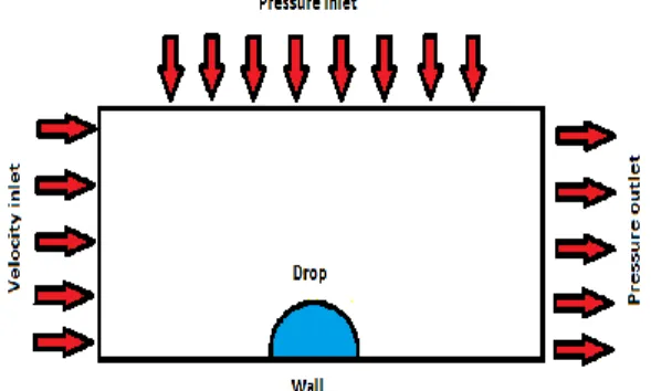
The study of drop dynamics has been studied numerically by considering three different types of problems. A rectangular parallelepiped of dimensions 30mm × 10mm × 20mm is taken. A hemispherical drop has been placed on the solid bottom surface of rectangular domain that is filled with air. The following boundary conditions have been given: Left plane of the domain as velocity inlet; Right side of the domain as pressure outlet; Top plane of the domain as pressure inlet; All other planes has been given the condition as
wall;
For the better analysis of the problem, three different cases have been considered as shown below:
Figure 1: Pictorial representation of problem with all the boundary conditions
The effect of Reynolds No. on the dynamics of the drop on flat horizontal plate under shear flow with adiabatic condition by considering three different sub-cases with drop diameter equals to 6 mm
1.1.1 In this section, the value of Reynolds number is taken as 1500, the drop is placed at X= 15 mm, Y= 0 mm, Z= 10 mm from the velocity inlet plane.
1.1.2 In this section, the value of Reynolds number is taken as 3000, the drop is placed at X= 15 mm, Y= 0 mm, Z= 10 mm from the velocity inlet plane.
1.1.3 In this section, the value of Reynolds number is taken as 4000,the drop is placed at X= 15 mm, Y= 0 mm, Z= 10 mm from the velocity inlet plane.
1.2 The effect of location on the dynamics of the drop on flat horizontal plate under shear flow with adiabatic condition by considering different sub-cases. 1.2.1 In this section, the diameter of the drop is taken as 6 mm. the drop is placed at X= 5 mm, Y= 0 mm, Z= 10 mm from the velocity inlet plane. The value of Reynolds number is taken as 3000.
1.2.2 In this section, the diameter of the drop is taken as 6 mm. the drop is placed at X= 15 mm, Y= 0 mm, Z= 10 mm from the velocity inlet plane. The value of Reynolds number is taken as 3000.
1.2.3 In this section, the diameter of the drop is taken as 10 mm. The drop is placed at X= 5 mm, Y= 0 mm, Z= 10 mm from the velocity inlet plane. The value of Reynolds number is taken as 3000.
1.2.4 In this, the diameter of the drop is taken as 10 mm. The drop is placed at X= 15 mm, Y= 0 mm, Z= 10 mm from the velocity inlet plane. The value of Reynolds number is taken as 3000.
1.3The effect of size on the dynamics of the drop on flat horizontal plate under shear flow with adiabatic condition by considering different sub-cases
1.3.1 In this section, the diameter of the drop is taken as 6 mm. the drop is placed at X= 15 mm, Y= 0 mm, Z= 10 mm from the velocity inlet plane. The value of Reynolds number is taken as 3000.
1.3.2 In this, the diameter of the drop is taken as 10 mm. The drop is placed at X= 15 mm, Y= 0 mm, Z= 10 mm from the velocity inlet plane. The value of Reynolds number is taken as 3000.
1.4The effect of heat flux on the dynamics of the drop on flat horizontal plate under shear flow with non-adiabatic condition by considering three different sub-cases.
1.4.1 In this case, heat flux equals to 1 MW is given to the bottom wall of the rectangular parallelepiped domain. Reynolds number is taken as 2000 to analyze how the drop evaporates while moving on the solid plate. The diameter of the drop is taken as 6 mm. The drop is located close to the velocity inlet plane i.e. X= 5 mm, Y= 0 mm, Z= 15 mm.
1.4.2 In this case, heat flux equals to 10 MW is given to the bottom wall of the rectangular parallelepiped domain. Reynolds number is taken as 2000 to analyze how the drop evaporates while moving on the solid plate. The diameter of the drop is taken as 6 mm. The drop is located close to the velocity inlet plane i.e. X= 5 mm, Y= 0 mm, Z= 15 mm.
1.4.3: In this case, heat flux equals to 100 MWis given to the bottom wall of the rectangular parallelepiped domain. Reynolds number is taken as 2000 to analyze how the drop evaporates while moving on the solid plate. The diameter of the drop is taken as 6 mm. The drop is located close to the velocity inlet plane i.e. X= 5 mm, Y= 0 mm, Z= 15 mm.
3.
NUMERICAL
SIMULATION
The advancement of high speed computing with high accuracy of numerical methods for the solution of physical problems, has made a big revolution in the way we approach fluid dynamics and heat transfer problems. Computational Fluid Dynamics (CFD) made the analysis of complex flow geometries much easier as compared to the earlier conventional methods. CFD provides a platform for combining fluid dynamics and numerical analysis. The need for CFD was realized in 1960s and 1970s
and was specifically developed for aerospace industries. Now a days the use of CFD can be seen in every disciplines such as mechanical, civil, electronics, electrical, chemical, ocean science, and biomedical engineering etc. CFD reduces the total cost and total time required for the analysis of a problem by replacing the analytical studies and experimental testing with numerical simulation methods.
CFD software consists of following three basic elements:
1. Pre processor 2. Main Solver 3. Post processor
The first step in CFD modeling is to understand the actual problem and define the computational domain. After mesh is generated which is a critical step of the pre- processing activity. This is the most important step of CFD because the accuracy of the solution and the computational time for the problem both depends on the mesh structure. Finer the mesh, more accurate the solution is but the mesh should not made very fine as that would take more time for computation. So an optimize grid size should be selected.
The role of the solver is to solve the equations as per the given information. It is consider to be the brain of the CFD software. The post- processor is the last step of the CFD software. It gives the useful data that can be used to get the final result and to draw some conclusion. The results that we get here may be in the form of vector plots of vector quantities such as velocity or in the form of contour plots of scalar quantities such as temperature, pressure etc.
3.1 GEOMETRY
As per the requirement of the problem, a rectangular parallelepiped domain has been created using workbench. Once the geometry is created with the given dimension, meshing operation is performed using workbench.
3.2 GRID PATTERN
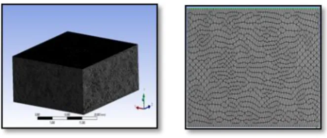
Uniform grid size of 0.5 mm has been chosen after performing a lengthy verification for various grid sizes. It has been further verified in Fluent for the shape of the drop and bubble. Tetrahedron grid pattern has been selected to solve this multiphase flow problem.
Figure 3.1: Figure showing the grid pattern used for this problem
3.3 SOLUTION STRATEGY
The modeling and meshing of all the problems have been done using workbench and hydrodynamic study has been carried out with the help of fluent. VOF model has been used for the analysis of the problem. Pressure-based 3-D solver has been used to numerically analyze the transient, non-linear, complex problems. The complex interface has been simulated using the Pressure Implicit Solution by Split Operator (PISO). Turbulent modeling, k-ϵ model is taken. Energy equation is switched off for all the cases of the 2.1 except 2.3.3 while it is switched ON for both the cases of 2.2.
3.4 GOVERNING EQUATIONS
The governing equations used for the analysis of this multi-phase flow problem are:
The Continuity Equation: principal of conservation
of mass is used for the derivation of continuity equation and is an important equation in any CFD problem. This equation plays a crucial role in the stability of the problem. The continuity equation in vector form is given as:
The Navier-Stroke’s Equation (Momentum equations): single set of momentum equations has
been solved in VOF modeling with pressure-based solver. The equation is given as below:
The Standard k-ε Model Equations: standard k-ε
model has been used for the turbulent modeling and is given below:
Where, is called as turbulent viscous coefficient and is given as;
3.5 BOUNDARY CONDITIONS
For 1.1, 1.1.1 the value of pressure inlet and pressure outlet is taken as atmospheric. The wall is given as adiabatic, no slip boundary condition. The magnitude of velocity inlet for 1.1.1.1, 1.1.1.2, and 1.1.1.3 is taken as 1.1 m/s, 3.2 m/s and 4.39 m/s respectively.
For 1.1.2, the value of pressure inlet and pressure outlet is kept as atmospheric. Adiabatic, no slip boundary condition is given to the wall. The magnitude of velocity inlet for all the subsets is taken as 3.2 m/s.
For case 1.1.3, pressure inlet and pressure outlet are assigned the value which is equal to the atmospheric pressure. In 1.1.3.1, wall is given the heat flux whose value is taken as 1 mw and the magnitude of velocity inlet is taken as 2.2 m/s. In 1.1.3.2, wall is given the heat flux whose value is taken as 10 mw and the magnitude of velocity inlet is taken as 2.2 m/s. In 1.1.3.3, wall is given the heat flux whose value is taken as 100 mw and the magnitude of velocity inlet is taken as 2.2 m/s. For 1.2, the wall is given adiabatic, no slip condition and the value of pressure outlet is taken as atmospheric pressure.
3.6 RESIDUAL AND CONVERGENCE
The accuracy level in RESIDUAL PLOT for continuity, X, Y, Z momentum equation, turbulent dissipation and turbulent kinetic energy equation is taken as and the accuracy level for energy equation is set to .
4.RESULTS AND DISCUSSION
4.1 DYNAMICS OF DROP WITH AND WITHOUT ADIABATIC WALL
Several cases have been studied under this section, which are given below.
4.1.1 The effect of Re:The effect of Reynolds Number on the dynamics of the drop on flat horizontal plate under shear flow with adiabatic condition by considering three different sub-cases with drop diameter equals to 6 mm, Drop-center location: (15, 0, 10).
In this case, the effect of shear velocity on the motion and shape change phenomena of the drop placed on a horizontal solid flat plate is studied. The data is saved after every 100 time steps with each time step size of 0.0001.The study has been
conducted by taking three different values of Reynolds number as 1500, 3000 and 4000. 1) 4.1.1.1 Re = 1500: The phase contours showing the shape change of the drop at various time instants during its motion for the Reynolds number equal to1500.
2)
3) 0.00 sec 0.05 sec 0.1 sec 4)
5) 0.15 sec 0.20 sec 0.25 sec 6)
7) 0.30 sec 0.35 sec 0.40 sec
Figure 4.1: Phase contours at various time
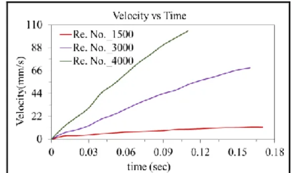
Figure 4.4: Variation of Drop velocity with time for different Reynolds number (Drop diameter: 6 mm, Drop-center location: X=15 mm, Y= 0 mm, Z=10 mm)
5.CONCLUSION
The hydrodynamics of drop and bubble under various boundary conditions (including adiabatic and non-adiabatic boundary condition) using numerical simulations have been studied. The effect of various parameters like: drop diameter, Reynolds no., position of drop on the dynamics is investigated. The numerical analysis of the drop and bubble are done using FVM with VOF model. At first, the kinetics of a drop on a horizontal solid surface under air flow (considering no heat transfer) is studied. Then the same problem with heat transfer through solid surface is considered. At last the hydrodynamics of a helium bubble through a vertical channel is studied. For each case the Reynolds number is varied for a considerable range.
1. It is clear from the present study that the drop motion on the horizontal flat surface is strongly affected by the Reynolds number. The time taken by the drop to cover the distance reduces as the Reynolds number increases.
2. Shape change phenomena of the drop is not much effected by the Reynolds number.
3. Position of the drop from the inlet has prominent effect on the drop dynamics. The effect of shear flow reduces as the distance of the drop from the inlet plane increases.
4. Size of the drop affects the velocity acquired by the drop at various time instant. Larger the size of the drop, lower the velocity acquired by the drop.
5. When the heat flux boundary conditions (non-adiabatic) on the solid horizontal surface is used, the size ( volume) of the drop will reduces as the evaporation will take part in the phenomena.
6. Size of the Helium bubble affects the dynamics of the bubble flowing through a vertical channel filled with water. On increasing the size of the bubble, it
takes less time to cover the distance as the buoyancy force increases.
VII.REFERENCES
I. Harlow, Francis H., and John P. Shannon. "The splash of a liquid drop.” Journal of Applied Physics 38.10 (1967): 3855-3866.
II. Trapaga, Gerardo, and Julian Szekely. "Mathematical modeling of the isothermal impingement of liquid droplets in spraying processes."Metallurgical
Transactions B 22.6 (1991): 901-914.
III. Pasandideh-Fard, M., S. Chandra, and J. Mostaghimi. "A three-dimensional model of droplet impact and solidification." International Journal of Heat and Mass
Transfer 45.11 (2002): 2229-2242.
IV. Staben, Michelle E., and Robert H. Davis. "Particle transport in Poiseuille flow in narrow channels." International journal of multiphase flow 31.5 (2005): 529-547.
V. Olbricht, W. L., and D. M. Kung. "The deformation and breakup of liquid drops in low Reynolds number flow through a capillary." Physics of Fluids A: Fluid
Dynamics (1989-1993) 4.7 (1992): 1347-1354.
VI. Martinez, M. J., and K. S. Udell. "Axisymmetric creeping motion of drops through circular tubes." Journal of fluid mechanics 210 (1990): 565-591.
VII. Tsai, T. M., and Michael J. Miksis. "Dynamics of a drop in a constricted capillary tube." Journal of Fluid
Mechanics 274 (1994): 197-217.
VIII. Šikalo, Š., et al. "Dynamic contact angle of spreading droplets: Experiments and simulations." Physics of
Fluids (1994-present) 17.6 (2005): 062103.
IX. Gunjal, Prashant R., Vivek V. Ranade, and Raghunath V. Chaudhari. "Dynamics of drop impact on solid surface: experiments and VOF simulations." AIChE
Journal 51.1 (2005): 59-78.
X. Pasandideh-Fard, M., S. Chandra, and J. Mostaghimi. "A three-dimensional model of droplet impact and solidification." International Journal of Heat and Mass
Transfer 45.11 (2002): 2229-2242.
XI. Das, Arup K., and Prasanta K. Das. "Simulation of drop movement over an inclined surface using smoothed particle hydrodynamics." Langmuir25.19 (2009): 11459-11466.
XII. Subramanian, R. Shankar, Nadjoua Moumen, and John B. McLaughlin. "Motion of a drop on a solid surface due to a wettability gradient."Langmuir 21.25 (2005): 11844-11849.
XIII. Pismen, Len M., and Uwe Thiele. "Asymptotic theory for a moving droplet driven by a wettability gradient." Physics of Fluids (1994-present) 18.4 (2006): 042104.
XIV. Grissom, William M., and F. A. Wierum. "Liquid spray cooling of a heated surface." International Journal of
Heat and Mass Transfer 24.2 (1981): 261-271.
XV. Attinger, D., Z. Zhao, and D. Poulikakos. "An experimental study of molten microdroplet surface deposition and solidification: transient behavior and wetting angle dynamics." Journal of Heat Transfer 122.3 (2000): 544-556.
XVI. Daniel, Susan, and Manoj K. Chaudhury. "Rectified motion of liquid drops on gradient surfaces induced by vibration." Langmuir 18.9 (2002): 3404-3407. XVII. Javadi, A., Bastani, D., Kragel, J, and Miller, R,
Interfacial Instability of Growing Drop: Experimental Study and Conceptual Analysis”, Colloid Surface A, 347(1-3), Pp. 167-174 (2009).
XVIII. Liao, Q., Shi, Y., Zhu, X., Wang, H. Appl. Therm. Eng. 2009, 29, 372-379.
XIX. Loth, E. “Quasi-Steady Shape and Drag of Deformable Bubbles and Drops”, Int. J. of Multiphase Flow, 34(6), pp. 523-546 (2008).
Author
GOSU NAGARAJU Research Scholar,
Department of Thermal Engineering, Aditya Engineering College, Surampalem, Andhra Pradesh, India.
K.L.KISHORE Associate Professor ,
Department of Mechanical Engineering, Aditya Engineering College, Surampalem, Andhra Pradesh, India.
V.SRINIVASA RAO, Professor,
Department of Mechanical Engineering, Aditya Engineering College, Surampalem, Andhra Pradesh, India.