458
©IJRASET: All Rights are Reserved
Analytical Study on Cold Formed Steel Back to
Back Supacee Section
Ganeshkumar R1 Suresh Babu S2, Dr.Leema Rose A3
1
PG Student, Valliammai Engineering College,Chennai, Tamil Nadu
2
Assistant Professor, Valliammai Engineering College,Chennai, Tamil Nadu
3
Associate Professor, Valliammai Engineering College,Chennai , Tamil Nadu
Abstract: Cold formed steel sections or light gauge steel sections are thin walled sections which are gaining popularity in recent years. These sections are cold-formed from carbon or low alloy steel sheet, strip, plate, or flat bar in cold-rolling machines or by press considered and worked on as a replacement hot rolled section. Unusual sectional configurations can be produced economically by cold forming operations, and consequently favourable strength‐to‐weight ratios can be obtained. Supacee section is the special case c section. This section is equipped with both intermediate and edge stiffeners. This section is tested of its flexural and compressive behaviour (ie., as both beam and column). In this present study the failure pattern and region of failure are to be analyzed .
Keywords: Cold form steel, compression member, flexural member, supacee section, stiffener
I. INTRODUCTION
Cold-formed steel (CFS) is the common term for products made by rolling or pressing steel into semi-finished or finished goods at relatively low temperatures (cold working). Cold-formed steel goods are created by the working of steel billet, bar, or sheet using stamping, rolling (including roll forming), or presses to deform it into a usable product. Cold-worked steel products, such as cold-rolled steel (CRS) bar stock and sheet, are commonly used in all areas of manufacturing of durable goods, such as appliances or automobiles, but the phrase cold-formed steel is most prevalently used to describe construction materials. In building construction, formed steel products can be classified into three categories: members, panels, and prefabricated assemblies. Typical cold-formed steel members such as studs, track, purlins, girts and angles are mainly used for carrying loads while panels and decks constitute useful surfaces such as floors, roofs and walls, in addition to resisting in-plane and out-of-plane surface loads. Prefabricated cold-formed steel assemblies include roof trusses, panelized walls or floors, and other prefabricated structural assemblies. Supacee section has a strengthened cross section than traditional c section. It is equipped with four intermediate stiffeners in web region (V-shaped) and distinctive edge stiffener with a return lip, where the lip portion is bent additionally than conventional 90 degree bending from flanges towards the section. This section is to analytically studied using ABAQUS software
II. LITERATURES
Jia-Hui Zhang, Ben Young “Compression tests of cold-formed steel I-shaped open sections with edge and web stiffeners” vol.52 (2011)
A series of column tests on cold-formed steel I-shaped open sections with edge and web stiffeners has been conducted. Tensile coupon tests were also conducted to obtain the material properties at both flat and corner portions of the sections. Initial local and overall geometric imperfections were measured. It was found that columns were failed by local, distortional, flexural buckling and the interaction of these buckling modes. The failure modes and ultimate strengths of the column specimens were presented. The direct strength method in the North American Specification and the Australian/New Zealand Standard was used to calculate the design strengths of the I-shaped open section columns.
459
©IJRASET: All Rights are Reserved
Reliability analysis has been performed to assess the current design rules in the North American Specification for the cold-formed steel non-symmetric lipped angle columns. It is shown that the current design rules are reliable for the sections having plate thickness of 1.9 mm, but this is not the case for the more slender sections having plate thicknesses of 1.0 and 1.5 mm.
P. Paczos “Experimental investigation of C-beams with non-standard flanges “Journal of Constructional Steel Research 93 (2014) The paper presents results of experimental investigations of stability and limit load of cold-formed thin-walled channel beams with non-standard flanges subjected to pure bending. Critical and limit loads were determined using a strength testing machine. Obtained results were compared with analytical solutions. The non-standard flanges of channel beams, having the shape of closed profiles, were more buckling-proof than standard flat flanges .The experimental, critical forces were lower than their theoretical approximations referring to buckling of the web. This was caused by the geometrical imperfections of actual beams. Moreover, relatively simple analytical formulas were used for an estimate. Analytical models of local buckling of flanges and web that can be found in the literature made it possible to estimate the bottom and upper limits of the presented solutions. The difference between experimental, critical moments and their theoretical estimations did not exceed 15%. The agreement between the experimental and analytical results was satisfactory. The presented results justify search for new shapes of cross-section of cold-formed thin-walled beams that were not included in standards.
Deenadhayalan.S, Iyappan.G.R, Suresh babu.S” Experimental Study on Compressive Behavior of Cold Formed Corrugated Steel Section “IJSRD -Vol. 5, Issue 02 (2017)
This paper focused on using cold formed steel as primary compression member. Cold-formed steel sections are usually formed in channel sections, Z-sections, hat sections, angle sections and other sections due to the manufacture process, and these sections are categorized as open sections. These sections can be also formed by connecting two or more sections together, for examples, an I-section formed by connecting two channel I-sections back-to-back, and a box I-section formed by connecting two channel I-sections in the flanges. Thickness of the section is 2.5mm and length is 800mm. These sections may fail by local buckling due to their short length. However, cold-formed steel sections can be strengthened by forming edge and web stiffeners in the I-shaped sections. Moreover by providing spacing 25mm between two channels strength can be increased. Ultimate load is predicted from ABAQUS then it is compared with experimental result. The maximum load carried by the specimen was found to be 229 KN with spacing. The load carrying capacity of the column has been increased by 21.8 % due to the provision of spacing.
P. Nandini,V.Kalyanaraman “Strength of cold-formed lipped channel beams under interaction of local, distortional and lateral torsional buckling” Thin-Walled Structures 48 (2010)
This paper elaborates about Cold-formed thin-walled lipped channel steel beams which may undergo buckling modes such as short half wavelength local buckling, intermediate half-wavelength distortional buckling and long half- wavelength lateral-torsional buckling or a combination of these before failure. ABAQUS software based on finite element analysis is used to analyse the interaction behaviour of these buckling modes in this study. The finite element model, after calibration with experimental results available in the literature, is used to perform parametric studies, to evaluate the behaviour and strength of such beams under different types of interactions due to variation of material and member properties. The large volume of synthetic data thus generated over a range of failure modes along with the available test results are used to evaluate different equations for calculating the strength of such cold-formed lipped channel beams.
Mohammad Reza Haidarali and David A. Nethercot “Local and distortional buckling of cold-formed steel beams with both edge and intermediate stiffeners in their compression flanges” Thin-Walled Structures 49 (2011)
In his paper the author presented the true buckling behaviour of cold-formed steel beams with both edge and intermediate stiffeners in their compression flanges has been predicted with the aid of advanced numerical modelling. A series of nonlinear finite element analyses has been carried out to investigate the flexural behaviour of cold- formed Z sections with both edge and intermediate stiffeners in their flanges, when the failure is controlled by local and/or distortional buckling. The effect of the size and position of intermediate stiffeners as well as the effect of the edge stiffener/intermediate stiffener interaction on the buckling behaviour and ultimate strength of these sections has been studied.
460
©IJRASET: All Rights are Reserved
A. Thus from the above literatures we can conclude that,
1) Use of intermediate and edge stiffener in web and flange region can resist local buckling in that region.
2) Use of stiffener in a section increases the load bearing capacity of the section.
3) Various failure conditions along with their area of influence, their loading condition and range of failure loads are noted.
4) Analytical study also carried out on various cases for the different type of profile on cold formed steel to justify the load bearing and buckling behaviour.
III. SECTIONPROPERTIES(SUPACEE SECTION)
In cold-formed steel constructions, built-up beams and columns are often fabricated from two channel sections. Connecting two channels together is a technique which can achieve a structurally desirable cold-formed steel section. With this technique the structural strength capacity of the section is expected to be more than double. Traditional, field fabricated, back to back or I-beam headers, consisting of two “C” sections with the webs screwed back to back, are the most popular built-up configuration in the construction industry. Due to this higher strength ‘Supacee sections’ has been selected.
IV. SPECIMENDETAILS
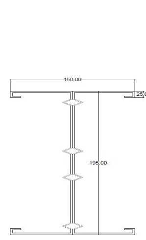
The cross section of supacee section is shown in figure 1,
Depth of web : 195mm
Width of flange : 150mm
Thickness : 2.5mm
Corrugation depth : 10mm
Lip of section : 25mm
[image:3.612.231.380.294.538.2]Return lip : 25mm
Figure 1 Cross Section of Supacee Section
A. Need Of Supacee Section
1) Supacee section is equipped both edge and web stiffener.
2) This section has a distinct Edge stiffener. It has a return lip feature with a distinct extra projection than conventional 90 degree lip projection.
3) Stiffener presented at web section is at distinct lengths, which are fixed after several experimental investigations.
4) This distinctive web cross section (with 4 stiffeners) helps in effectively resisting the local buckling in web region.
5) Return lip provision present helps in increasing load bearing capacity of the section and reducing the local buckling failure in flange region.
V. ABAQUSSOFTWARE
461
©IJRASET: All Rights are Reserved
behaviour of new materials, or simulate a discrete manufacturing process. ABAQUS 6.12 version software is used to create modelling, predict load, displacement, rotation, flexure behaviour for any kind of model.
Every complete finite-element analysis consists of 3 separate stages:
A. Pre-processing or modelling: This stage involves creating an input file which contains an engineer's design for a finite-element analyzer (also called "solver").
B. Processing or finite element analysis: This stage produces an output visual file.
C. Post-processing or generating report, image, animation, etc. from the output file: This stage is a visual rendering stage
VI. SOFTWAREANALYSIS
[image:4.612.198.416.268.476.2]The geometry of any section to be analysed are first modelled under various stages before analysing. This modelling is done to provide necessary details shape of model, dimensions of cross section, their interaction conditions, type of mesh used for meshing, the value of load applied and at which precise location. The column and beam specimen were modelled using a 3D modelling tool. Various iterations have to be given to the beam and column models to achieve its maximum load carrying capacity and its nature of failure at that load.
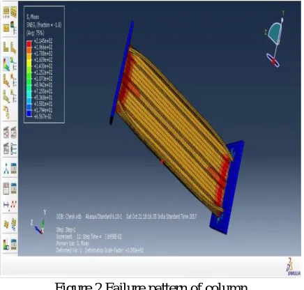
Figure 2 Failure pattern of column
The figure 2 indicate failure pattern of specimen when it is axially loaded from top (column). The area of failure is mainly in flange region. Due the provision of four intermediate stiffeners in web region there is very little damage even after reaching failure condition of the specimen. The maximum deflection value from ABAQUS software is 0.12 mm and ultimate load is 128.5kN. Global buckling occurs along the length of stiffened web section. The deflection increases till the middle section and decreases to the edge portion.
[image:4.612.192.426.560.721.2]462
©IJRASET: All Rights are Reserved
The figure 3 indicate failure pattern of supacee section on flexural loading condition. Here the area of failure is observed mainly around the area of loading and near support. The cause of failure noted is mainly due to local buckling. This local bucking in flange region leads to collapse of specimen and fail when reaching its maximum load. The maximum deflection value from ABAQUS software is 7.43 mm and ultimate load is 63kN
V. RESULTS AND DISCUSSIONS
A. Supacee section as a flexural member, on analysis bears a maximum load of 63 kN where as conventional cold formed steel I
section bears a load within the range of 28 kN to 35 kN for 1.2 meter span.
B. Supacee section as a compressive member, on analysis bears a maximum load of 128 KN whereas conventional cold formed
steel I section bears a load within the range 78 kN to 86kN for a span of one meter.
C. This clearly indicates that this supacee section shows enhanced strength when compared to conventional built up I section for
both compression and flexural member.
D. This improved cross section enables the use of this section even as a primary compression member (as a column which cold formed steel section are not used till date) and as purlins and rafters in industrial roofing constructions.
REFERENCES
[1] Ben Young and Ehab Ellobody” Finite element analysis of cold-formed steel lipped angle compression members” Advances in Steel Structures, Vol. I [2] P. Nandini,V.Kalyanaraman “Strength of cold-formed lipped channel beams under interaction of local, distortional and lateral torsional buckling” Thin-Walled
Structures 48 (2010)
[3] Mohammad Reza Haidarali and David A. Nethercot “Local and distortional buckling of cold-formed steel beams with both edge and intermediate stiffeners in their compression flanges” Thin-Walled Structures 49 (2011)
[4] P. Paczos “Experimental investigation of C-beams with non-standard flanges“ Journal of Constructional Steel Research 93 (2014)
[5] Ben Young and Gregory J. Hancock” Tests of Channels Subjected to Combined Bending and Web Crippling” Journal of structural engineering (march 2002) [6] YuChen, XixiangChen, ChaoyangWang“Experimental and finite element analysis research on cold-formed steel lipped channel beams under web crippling”
Thin-Walled Structures 87 (2015)
[7] Ben Young, Ju Chen” Column tests of cold-formed steel non-symmetric lipped angle sections” Journal of Constructional Steel Research 64 (2008)
[8] Hélder D.Craveiro, JoãoPaulo, C.Rodrigues , LuísLaím “Buckling resistance of axially loaded cold-formed steel columns “Thin-Walled Structures 106 (2016) [9] Jia-Hui Zhang, Ben Young“Compression tests of cold-formed steel I-shaped open sections with edge and web stiffeners” vol.52 (2011)