2272 IJSTR©2020
Experimental Study And Numerical Modelling On
The Behaviour Of Built-Up Cold-Formed Steel
Beams With Diagonal Web Bars
J. Samuel, P.S. JoannaAbstract: The experimental investigation and numerical simulation of the behaviour of built-up Cold-Formed Steel (CFS) I beams with diagonal reinforcing bars welded to the web in order to restrain web buckling is presented in this paper. Experiments were conducted on three types of CFS beams. In the first case, no diagonal bars were present, in the second case diagonal bars were welded to the web in the shear zones and in the third case diagonal bars were provided in the shear zones and flexure zone. The simply supported beams were subjected to two-point loading. Load carrying capacity, deflection, strain and failure parameters like lateral torsional buckling and local buckling were examined. It is found that the beam with diagonal bars in the shear zone and flexural zone had greater load carrying capacity and underwent lesser strain than the other two cases. Also, numerical analysis using ANSYS WORKBENCH was done to find the flexural behaviour of CFS beams with diagonal web reinforcing bars which concurred with the test results. The study also proves that Finite Element (FE) modeling can be relied upon as a sustainable alternative to expensive experimental testing
Index Terms: Cold-Formed Steel, Diagonal Reinforcing Bars, Finite Element Modelling, I Beam, Load Carrying Capacity, Local Buckling, Strain.
—————————— ——————————
1.
INTRODUCTION
COLD-formed steel (CFS) is increasingly finding applications in many engineering products. It is easy to cut, bend and join cold-formed steel sheets to form various useful sections. ‘I’ section is considered ideal for flexure and compression members and lips augment the post buckling strength of the member. Experimental investigation was conducted on CFS beams with corrugated webs and validated the experimental results with finite element analysis results. Web corrugation angle of 30◦ had higher moment capacity than flat web or webs with 45◦ angles (Divahar and Joanna 2018) [1]. Moment carrying capacity of channel beam with lips obtained from FE analysis was compared with BS 5950: part 5 and IS 801: 1975 and found to be in close agreement. It was found that provision of torsional restraint increases the flexural capacity. (Kandasamy et al 2016) [2] The results of the parametric study by FE Analysis carried out on stainless-CFS beams at elevated temperatures were validated with the experimental results (Ju and Wei-Liang 2008) [3]. A FE model was developed to accurately simulate the test results of web stiffened CFS column with channel section with different types of stiffeners in the edge under axial compressive load and good correlation was obtained between the finite element model and test results (Manikandan et al. 2017) [4] Non-linear FE analysis was carried out on CFS channels subjected to web crippling under loading on flange conditions as per the North American and Australian/New Zealand specification to study web crippling load and failure modes, and web deformation curves of the FE models which agreed with tests. Parametric studies on varied channel dimensions of the FE models carried out, and updated coefficients and new formulae for calculating design strength was proposed (Wei-xin et al.2006) [5]. Numerical models were developed on CFS purlins and beams with accurately represented physical features and validated with available test datum. All variables
found in site conditions were applied on the validated models and the generated pool of useful results was used to gain insights on the behaviour and improve design procedures (Kyvelou et al 2019) [6]. Beam elements of CFS portal frames could be idealized using FE models if appropriate allowances for connection deformation under loading are made. (Lim and Nethercot 2004) [7]. FE models were validated by simulating tests on C- and Z- section CFS members. Ultimate strenght, yield stress and moment gradient effect were studied and an elastic buckling moment to include the effect of moment gradient was proposed (Yu and Schafer 2006) [8]. In this paper experiments were conducted on CFS beams wih diagonal reinforcing bars welded to the web to study their flexural behaviour. A total of six CFS beams were tested out of which two were without diagonal reinforcing bars, two with diagonal bars welded to the web in the shear zones and two with diagonal bars provided in the shear zones and flexure zone. Numerical analysis using ANSYS WORKBENCH was carried out to find out the flexual behaviour of CFS beams with diagonal web reinforcing bars and validated with the experimental results.
2
EXPERIMENTAL
TESTS
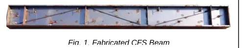
Beams were fabricated from cold-formed steel sheets of thickness 2mm. Flange and web were cut to dimensions and bent to form the ‘I’ section with lips. The beam’s web was 150mm deep and 2mm thick, and the flange was 100mm wide and 2mm thick. The flange ends were bent to form 10mm lips. Stiffeners of 2mm thickness were welded to the web at the end supports and loading positions. Diagonals of 6mm diameter high yield strength deformed bars were welded to the webs. These bars had yield strength of 415 MPa and had ribs on the surface. All the components were welded using spot welds to form the ‘I’ beam section. Three types of specimens were fabricated. The first type had no diagonal bars, the second type had rebar diagonals in shear zone and third type had rebar diagonals in shear and flexure zone welded to the web. CFS beams of these six models had the same dimensions and were fabicated from the same sheet. Figure 1 shows the fabrication of the beam.
————————————————
J Samuel is currently teaching structural engineering in Hindustan Institute of Technology & Science, India, PH +919094844764. E-mail: [email protected]
2273 IJSTR©2020
The fabricated beams were tested under two-point loads in the laboratory as shown in figure 2a and 2b. Four Strain gauges and five linear variable displacement transducers (LVDT) were fixed on the beams to measure the strains and vertical deflections respectively during load application. To measure strains and deflections in the CFS beams, strain gauges and LVDTs were used. The load was applied gradually till failure of the beams. All the measurements were recorded by a data logger.
3 FINIT ELEMENT MODELLING
3.1 Geometry preparation
Design modeler was used to model the CFS ‘I’-beam with lipped flanges. Loading and support structures were also modeled to replicate the practical conditions. The dimensions of the beam are 100mm width and 150 mm depth. The flanges were provided with10 mm lips at the edges. All the components were 2mm thick and 2000mm long.Stiffener plates are also of the same thickness.Three different geometry configurations were designed as follows
a) I-beam lipped section without diagonal bars.
b) I-beam lipped section with diagonal bars in shear zone (8mm Diameter.)
c) I-beam lipped section with diagonal bars in shear and flexure zone (8mm Diameter).
After creating the ’I’-beam solid geometry, Mid-surface had been extracted to simplify the geometry for FE modeling. Since the thickness to length ratio of the specimen exceeded 1:10, mid-surface methodology had been implemented. For uniform thickness components, performing simulation with surface gives more conservative results than solid geometries. Spot weld points have been introduced between web and flanges of ‘I’-beam section with a spacing of 50mm as in the experimental specimen. Stiffener plate and diagonal bars were also attached to the ‘I’-beam web by 50mm spaced spot welds. Stiffener plates have been positioned in the I-beam in such a way that it captures the location of loading and extreme ends.
3.2 Finite element model
Finite Element models were created incorporating the test specimen details as follows: Flange, web and the vertical stiffener portion of the ‘I’ -Beam were modeled using Quad element SHELL181 and the diagonal rebar component was modeled using BEAM188 which is a one dimensional beam element. Finite element modeling details are provided in the table 1..
3.3 Finite Elements
The finite element types used in this model are SHELL181 and BEAM188, described as follows: SHELL181 is ideal for analyzing thin shell structures. It is an element with four nodes, having six degrees of freedom at each node. In mesh generation, the collapsing nodal triangular option was used in elements as filler. SHELL181 is shown in figure 3.
TABLE1 MESH METRICS
============================ Parameters Specification
Jacobian 0.6
Aspect ratio 5
Warpage angle 15◦
Skewing angle 40◦
Quad minimum angle 40◦ Quad maximum angle 140◦ ============================ Fig. 1. Fabricated CFS Beam
Fig. 2a. Test set up
Fig. 2a. Schematic diagram of beam testing
2274 IJSTR©2020
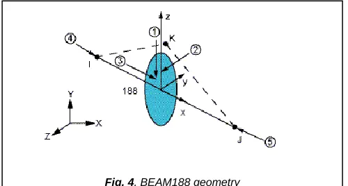
BEAM188 is preferable for analysing thin to medium thick beam structures. The element follows Timoshenko beam theory with shear deformation effects. BEAM188 has alternatives for measuring unrestrained and restrained warping of cross-sections. The element can be linear, quadratic, or cubic beam with two nodes in three dimensions. BEAM188 has seven degrees of freedom at each node with an additional seventh DOF for accommodating warping magnitude. For linear, large rotation and large strain nonlinear applications this element is considered ideal. The geometry is shown in figure 4.
3.4 Material properties
Cold-formed steel material is used for web, flanges and stiffeners of the FE model with yield strength of 380 N/mm2. Figure 5 shows the stress- strain curve used for this simulation. Coupon test was performed to ascertain the yield strength, Young’s modulus, and Poisson’s ratio.
3.5 Simulation analysis
FE analysis was performed on the models under four-point bending condition. The FE analysis results were compared with test results, to examine the predictability and validity of the created FE model. The mesh size was finalized using mesh convergence tests on the models. The meshed model is shown in figure 6. The strain and deflections are measured exactly equivalent to the test setup location of the strain gauge and LVDT.
3.6 Boundary condition and load application
The geometry created to replicate the actual experimental setup. Instead of applying constraints on the I-beam structure, support roller and support plate (Flat member) were introduced at the bottom of the I-beam as rigids. The loading and boundary conditions are shown in figure 7.
The support plate was assigned with bonded contact with the I-Beam bottom face and support roller was modelled as a contact with friction, with friction co-efficient of 0.2. Because of this contact provision, the I-beam structure could slip over the support roller and exhibit actual experimental behavior. Both support roller and support plate have been constrained in all degrees of freedom. Loading rollers were modeled as rigids and assigned frictional contacts with I-beam. Each loading roller was constrained in all degrees of freedom except the loading direction via remote displacement and equal remote forces were applied along the loading direction.
4
RESULTS AND DISCUSSION
4.1 Load versus deflection
The load versus deflection at centre for the three simulation cases agrees with experiment. The deflection after ultimate load could not processed by the software because of model became unstable causing the program to abort. It is found that the beam with diagonals in shear zones and flexural zone has the highest load carrying capacity. The maximum ultimate load carrying capacity of the test beams without diagonal bars, with diagonal bars at shear zones and with diagonal bar in shear zones and flexure zone are 15kN, 31kN and 36kN respectively and it is 13kN, 33kN and 35 kN respectively for FE simulation. Thus there is a maximum difference of 6% between the experimental and numerical results. Also the load carrying capacity of the beam with diagonal bars in shear zone and flexure zone is 1.4 times more than the beam without diagonal bars.
Fig. 4. BEAM188 geometry
Fig. 5. Stress-strain curve of CFS coupon
Fig. 7.Loading and constraints
Fig. 6. FE mesh of the model
2275 IJSTR©2020
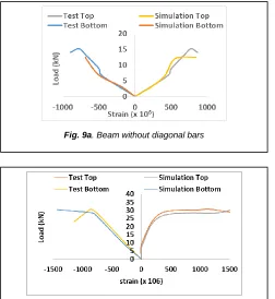
4.2 Load versus strain
The Load versus strain curves were plotted. The simulation model and the experimental results correlate well. load versus deflection at centre for the three simulation cases agrees with experiment
4.3 Failure patterns
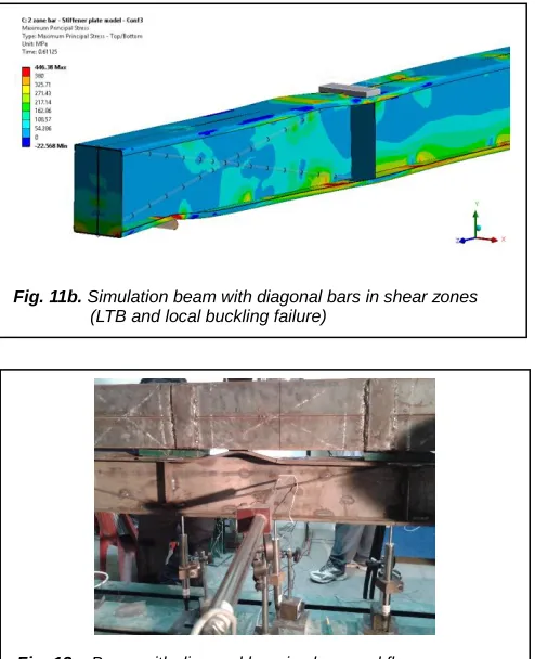
The failure patterns of the test and simulation beams are shown in figures 10a to 12a and 10b to 12b respectively. They are found to mimic the actual experimental failure.
.
Fig. 8b.. Beam with diagonal bars in shear zone
Fig. 8c. Beam with diagonal bars in shear and flexure zone
Fig. 9a. Beam without diagonal bars
Fig. 9b. Beam with diagonal bars in shear zone
Fig. 9c. Beam with diagonal bars in shear and flexure zone
Fig. 10a.. Test beam without diagonal bars (lateral torsional buckling failure)
Fig. 10b.. Simulation beam without diagonal bars (lateral torsional buckling failure)
2276 IJSTR©2020
The beams without diagonal bars failed by lateral torsional buckling (LTB). All the other beams failed by local buckling between the weld points. They also exhibited lateral torsional buckling to a minor degree
5 CONCLUSION
The results of the numerical model of cold-formed steel beams was validated with the experimental results. Provision of diagonal bars in the shear zones and flexure zone have helped the beam to resist more loads than the beam without diagonal bars. The provision of diagonal bars in the shear zone alone increases the load carrying capacity by 1.1 time and the provision of diagonal bars in shear zones and flexure zone increases it by 1.4 times when compared with the beam
without diagonal bars. The beams without diagonal bars failed by lateral torsional buckling. All the other beams failed by local buckling between the weld points. They also exhibited lateral torsional buckling to a minor degree. Also, numerical analysis using ANSYS WORKBENCH carried out to find the flexural behaviour of CFS beams with diagonal web reinforcing bars agreed well with the test results.
REFERENCES
[1] Divahar,R. and Joanna,P.S. (2018) Numerical simulation and experimental investigation on static behavior of cold-formed steel beams with trapezoidally corrugated web by varying depth-thickness ratio Asian Journal of Civil Engineering.
[2] Kandasamy, R., Thenmozhi, R. and Jeyagopal, L.S. (2016) Flexural-torsional buckling tests of cold-formed lipped channel beams under restrained boundary conditions, International journal of steel structures, pp.765-776
[3] Chen, Ju. And Jin, Wei-liang. (2008) Behaviour of cold-formed stainless-steel beams at elevated temperatures, Journal of Zhejiang University, pp.1507-1513.
[4] Manikandan, P., Balaji, S., Sukumar, S. and Sivakumar,M. (2017) Experimental and numerical analysis of web stiffened cold-formed steel channel column with various types of edge stiffener, International journal of advanced structural engineering, pp.129-138.
[5] Ren, Wei-xin., Fang, Sheng-En. And Young, Ben. (2006) Finite-element simulation and design of cold-formed steel channels subjected to web crippling, Journal of Structural Engineering, ASCE (132), pp.1967-1975.
[6] Kyvelou, P. C. Kyprianou, L. Gardner, D.A. Nethercot, (2019) Challenges and solutions associated with the simulation and design of cold-formed steel structural systems, Elsevier.
[7] James B.P.Lim and David A.Nethercot, (2004) Finite element idealialization of a cold-formed steel portal frame, ASCE, Journal of Structural Engineering, pp.78-94. [8] Yu, Cheng and Schafer, Benjamin W., (2006) Finite
Element Modeling of Cold-formed Steel Beams Validation and Application, International Specialty Conference on Cold-Formed Steel Structures.
Fig. 11b. Simulation beam with diagonal bars in shear zones (LTB and local buckling failure)
Fig. 12a. Beam with diagonal bars in shear and flexure zone (lateral torsional buckling, LTB failure)