American
Journal
r ~ f
Computational
Linguistics
M i c r o f i c h e 1 6S ~ M
L EDIGITAL
SPEECHSYNTHESIG
William Mw Fisher and Aw Maynard Engebretson
C e n t r a l I n s - t ~ i t u t e f o r the D e a f
818 S o u t h Euclid Street
St. Louis, Mo. 63110
and
Biomedical Computer Laboratory
Washington University ~ c h o o l of Medicine 700 South Euclid Street
St. Louis- M o m 63110
c o p y r i g h t 1 9 7 5
R e l a t i v e l y
s i m p l ~
computeraiethods
f o rs y n t h e s i a i n g
Beech
t o
be
used
i n p h o n e t i c/perceptual
research
are
p r e s e n t e d ,wit
f:
p a r t i c u l a rr e f e r e n c e s
t ot h e problm~
and
successesencountered
i n
t h e devel-
opment of
suoh
a
system
a t C e h t r a l
inatitUte
f o rt h e
Deaf andthe
Biomedical
Computer
Laboratory
of
Washington University,
The
purpose of
t h i s
paper i st o
p r e s e n ta
synthesis
and
c l a r i f i c a t i o nof
e s t a b l i s h e dmethods
s oa s
t oencourage
o t h e r
computational
l i n -
g u i s t s t o t a c k l e
d i g i t a lspeech
synthesf
e.
The
approach
is
semi-
tutorial
: c r u c i a lalgorithms
a r e
g i v e n
i n
Fortran
o r
block-diagram
form,
and b i b l i o g r a p h i c
referenoes
t h a t
were
found t obe
mostuseful
i n t h e
eystem
developmentare
listed
and
dlscilaeed.The
system
described requires
a
minimum
ofhardware;
a mini-
computer
i ss u f f i c i e n t ,
i fit
i s
equipped
w i t h
tape
or
diek
secondary
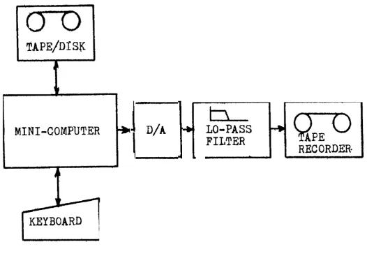
memory.The
sound
pressure wave
is
calculated
e n t i r e l yby
s o f t w a r eand
onlya digital-to-analog
converter and
a
low-pass
f i l t e r .
are
.required
to convert
it
to
a
recordable
e l e c t r i c a l
s i g n a l .The
vocalapparatus
i ss i m u l a t e d
bya
roughmodel
which
i sstill
general enough
t omate
most speecheounds.
The
twomain
types ofexcitation o f
the
vocal
t r a c t
--
periodic g l o t t a l waves f o r v o i c i n gand
random noise f o r f r i c a t i o n ora s p i r a t i o n
--
a r e
supplied byalgorithms
presented
a s
function
s u b r ~ u t i n e s .
The
effect o f the vocalt r a c t
onthese
i n p u t s i s modelled by combinationsof
t h r e e otherelemental
f u n c t i o n s , whosecoding
i s
based on r e c u r s i v eequa-
tion
theory
f o r computational e f f i c i e n c y .A
resonance p r o v i d e s t h euser
with a
means
f o ra c c e n t u a t i n g
t h es i g n a l
a ta
c e r t a i nf r e q u e n -
cy,
such
a s
a formant
frequencyof
a
vowel;an
anti-resonance
o rnotch filter
i s
p r o v i d e dt o
c u tback
t h e energya t
a c e r t a i n
f r e - quency,as
in simulation
of
the
nasal
a n t i - f o r m a n t ;and
a
r a d i a t i o n -effect
s u b r o u t i n e s i m u l a t e sthe
e f f e c t onthe
speech signal ofpassage
from
t h e l i p s through a s h o r t s t r e t c h of a i r . Empiricallyobtained
wave
shapesand
s p e c t r a of t h eo u t p u t s
of these f i v ebasic
f u n c t i o n s a r e
g i v e n i n o r d e r t o givet h e
r e a d e ra
b e t t e r f e e l f o r what they do.These f i v e
elements
can be combinedin a
number
ofways.
A
d e t a i l e d d i s c u s s i o n i s given f o r qne of t h e s i m p l e s t r e a s o n a b l e models,i n
which t h e g l o t t a l wave andf r i c a t i o n
g e n e r a t o r s e x c i t e aseries
of t h r e e v a r i a b l e r e s o n a t o r s , usinga
s e t o f f i x e d reso-nances
t osimulhte
h i g h e r frequency formantsi n
a d d i t i o n t o t h er a d i a t i o n - e f f e c t simulator. S e v e r a l o t h e r more complex arrangements a r e
presented,
i n c l u d i n g p a r a l l e l r e s o n a t o r modelsdnd
models w i t hs e p a r a t e
f i l t e r s f o r shaping voiced, f r i c a t i v e , and n a s a l components,and
t h e i r advantagesand
disadvantagesa r e
discussed.
An
example i s g i v e n ofa
complete modularF o r t r a n
programg e n e r a t i n g t h e word
% e a t t t .
The equations f o r specifying t h e param-eters ~ w 3 r o l l i n g
t h e
elemental f u n c t i o n swere
d e r i v e d , w i t h muche f f o r t , from
a n a l y s t s
ofone
token u t t e r a n c e , and spectrographs oft h e
real
and s y n t h e t i cwords
a r e
shown t oi l l u s t r a t e
t h e degree ofn a t u r a l n e s s obtainable
with t h e simple t h r e e - r e s o n a t o r s e r i e s model.A simpler example for
g e n e r a t i n g a
c o n s t a n t vowel sound i s alsogiven,
along d t ha
summary of d a t au s e f u l
i nmaking
many vowels.This
paper
is
a
s l i g h t l yexpanded
v e r s i o nof
one given o r a l l yTable
of
Contents
Page
No
I.
Introduction
e m m m a m a a a m m m . . ~ . . ~ e 4111.
Basic Elements
A .
Sources
* m w s . . . r . e m a r . m m r m 101.
G l p t t a lWave
Generator
.
.
.
. .
10
2 .
White
Noise Generator
. b a r n . . . I .16
3.
Spectral
Shapingblements
. .
. . .
171.
Resonances
and
Anti-resonances
.
. . .
,1 7
Radiation
Effect
I V ,
O r g a n i z a t i o a o f E l e m e n t s
. .
.
.
.
.
.
. .
.
.
.
.
.
22A.
The
Simplest
Model
l. . .
.
.
.
.
B.
Control
. . . . . . .
. . .
. . . .
2 8C .
Other
Models
w . . .
30Parallel
Formant
2.
Separate
Noise
Shaping
Channel
.
,3.
OtherMore Complex
Models
.
. .
.
.
.
3 3P .
A
Complete
Example l.
.
.
.
.
,,.
. .
.
33
V.
F i n a l Reaarks
, . . a n .. .
. . .
44
5 .
Introduction
Several
years ago,
it was
decided
t h a t
t h e
Research Depart-
ment
a t
Central
I n s t i t u t e
f a r t h e ,
Deaf
in
S t .
Louis should have
a
digital
speech
synthesizer
to
aid s t u d i e s inpsychoacoustios.
arid
phonetic
perception.
The
equipment
on
hand
a t
t h e
time
coneisted
p r i m a r i l yo f
a 12
- b i t - w ~ r dmini
-computer
with
keyboard
and
scope,
with
special-purpose
hardware
f
a fdoing
d i g i t a l - t o -
analog conversion,
low-pass
filtering,
and
floating-point
arithmetic
Mare peripheral
devf cesand
core
memory have
R a w
b&n
added,
We
have
beenworking
since
then
on writing
digital
computer programs to synthesize
speech s t u d y i n gthe
literature
and
gaining practicalexperience.
Almost
a l l
of
t h e theory and
techniques
necessary to programthe
synthesis ofE r g l i s h
sounds
oan
be
found
in
published literature,
b u t
in
bits
and
pleces, here
and
t h e r e .
Utilizing
the
cantributions
o f
many
authors,
plus our
own
experience,
we
present
and
explain
a
basic
programfor
synthesizmg speech,in
the
hopethat computa-
tional
lingdistswho
have not
worked
withlow-level
speech phenomena
may
be encouraged t o programsynthesizers.
The use of
s y n t h e t
ic-speechstimuli
h a s been ext xemely import-
a n t
to
t h einvestigation
of the
p e r ~ e p t u a l l y ~ d i s t i n c t i v ef e a t u r e s
of
speech
and
oflow-level
phonologicalr u l e s ,
but much work
remains
undone. Synthesizing speech i s
c l e a r l y
importantto phonetic
research,
and
t h e f i e l d could
well
usemore
researchers
w i t h
linguistic
t r a i n i n g .
The
system
described
in
this paperrequires
11.
Overview
Synthesizers use
varying
a m o ~ n t s
of
8peciai-purpose
hardware.The
type
ofsynthesis
wedesc.ribe
here
uses t h ebare
minimum,
calculatiag
t h e
speech wave
on
a
d i g i t a l
c ~ m p u t e r
and f e q u i r i n g
only
a
d i g i t a l - t o - a n a l o g
convertqr
and
a
low-pass
analog f i l t e r
a s
s p e c i a l .
hardware.
T h i s
minimum
s e t of equipment
i s
shown
i n
Figure
1,
page
6 .
If
we
asstuset h a t
tape
o r
disk
secondary
storage
i sa v a i l a b l e ,
t h e n a 4
k
12-bit-word mini-computer
i ss u f f i c -
i e n t l y
large,
and
a
12-bit
D / A
c o n v e r t e r ,
will
g l v eenough
dynamicrange.
Ohce
t h e speech
wave
i sgenerated
and stored on
t a p e
o rd i s k ,
t h e r e i s
problem ofwriting
a
program
t o
output enough
of
i t
synchronously
a t a
f a s t enough
r a t e .
W
w i l l not
e
gof u r t h e r i n t o
t h i s
pmblem
here, s i n c e t h e s o l u t i o n will
depend
on
t h e p a r t i c u l a r
machine
i n s t a l l a t i o n you
have.
Whatever
output
sample
r a t e
you
achieve,
t h e r e
aret w
t h i n g s t o
note:
t h e
analog low-pass f i l t e r
should
pass
only
frequencies below
t h e output
samplerate,
and t h e
output
sample
r a t e
i s
a
parameter
whose v a l u e
mustbe
fed
i n t o t h e
d i g i t a l
c a l ' c u l a t i o n s .
Although
our
synthesizer
can
bedescribed
as at e x m i n a l
analog
model of
t h e vocal
apparatus,
t h e
a t t i t u d e
we
t a k e i s
t h a t our method
o fs y n t h e s i s i s
used
r a t h e r
t o
produce
t h e
sig-nificant
a c o u s t i c f e a t u r e s
ofspeech. To s e t t h e s t a g e f o r
a n
understanding
p ft h e
s y n t h e s i z e r
presented
here,
and
for
t h e
benefit
oft h o s e
not
f a m i l i a r with
acoustic
phonetics,
l e t
us
KEY BOARD
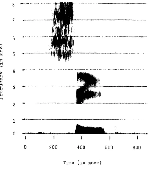
[image:6.786.131.658.228.628.2]Figure
2,page
8,shorn
a typicalspectrogram
oft h e
word
Itseat.
Frequency
i s
t h e v e r t i c a l
axis,
time
t h e
h o r i z o n t a l ,and
darker marks i n d i c a t e
more
energy. The mottledarea
a tt h e
upperl e f t
is t h equasi-random noise
of t h e/ e l
sound.
Tomake
o t h e r f r i c a t i v e s ,suck
as
f1,
weneed
t o a l t e r
t h efrequency
spectrum and
intensity oft h e
noise.
Thedark
horizontal
bands
in the
c e n t e r
a r e
c o n c e n t r a t i o n s of,energy
- -
resonances
called
~ t f o r m a n t s ~ ~
- -
c h a x a c t e f i s t i c of vowelsounds.
To
makedifferent vowels,
we
;reed t ochange
t h ec e n t e r
frequenaees,bandwidths,
and r e l a t i v e i n t e n s i t i e s
ofthe
t h x e elower
formants visible here.
There a r eh i g h e r -
frequency formants,
which
donot
showup
w e l li n
t h i s spectro-gram, but t h e y seem t o be
important
only t o t h enaturalness
of
the
speech,n o t
t owhich
vowelis
perceived. Note t h ebeginning
and
ending slopes of
t h e formants;these
formant
t r a n s i t i o n s a r e
crucial
t o t h e perception of o c c l u s i v e con-sonants
such a s
t h e stops,
,
and
/g/,And
f i n a l l y ,t h e
vertical mark
a t
t h et a r
right i s a burst o t noise marking t h erelease
of t h ef i n a l
consonant,The
detailed
algorithms we present here w i l l be expressed,in
Fortran
f o r c l a r i t y , although t h e s y n t h e s i z e r w i t hwhich
we
have
had
the most experience i s codedin
assembly
language.W
e
a r e
presently c o n v e r t i n g t o F o r t r a n ,and
t h esubroutines
and
f i n a l
example programl i s t e d
i n
t h i s paperhave
b ~ e h testedin
their:F o r t r a n
form.Time
[ i n
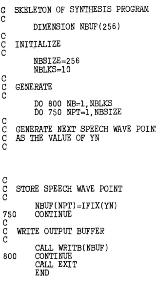
msec)SKELETON
OF
SYNTHESIS
PROGRAM
DIMENSION
NBUF
( 2 5 6 )GENERATE
GENERATE
NEXT
SPEECH
WAVE
POINT
A3
THE
VALUE
OF
YN
C
C
STORE
SPEECH
WAVE
POINT
C
NBUF
(NPT)
=IFIX(YN)
750
CONTINUE
C
C
WRITE
OUTPUT
BUFFER
CCALL
WRITB
(NBUF
)800
CONTINUE
[image:9.786.196.517.160.760.2]CAZL E X I T
END
Figure
3 .
Over-all
Synthesiaer
Program
Logic.
WRITB
i s asubroutine
t owrite
t h e
c o n t e n t s
3.0
this
logic i s thatwe
s y n t h e s i z ethe
speecha
pointst
a
tihe,in
one paaa, storing eachbuffer-full
on tapeor disk as it
isgenerated. This program will produce an integral number of
buffer-loads, but other methods for terminating
the
main loopare easy to implement.
111. Basic Elements
T h e r e a r e five b a s i c e l e m e n t s i n t h i s method of speech synthesis :
1.
A
glottal wave generator, with controls f o r repetitionrate (pitch) and amplitude;
2.
A
white-noise generator, w i t h a control for amplitude;3.
A
resonant filter, w i t h center frequency and bandwidthcontrols ;
4.
An
anti-resonant filter, with similar controls;and 5.
A
radiation-effect simulator.T k s e five elements can be connected in
a
variety of ways t pproduce models of greater or lesser complexity. me glottal wave
generator and noise generator produce sounds whose spectra are
then shaped by combinations of the other elementss,
A.
Sources1. Glottal-Wave Generator
Natural glottal waves, while subject to much variation, are
usually considered to consist of three parts: a glottis-opening
phase in which t h e volume velocity is increasing,
a
glottis-closingphase in which the volume velocity is decreasing, and a g l o t t i s -
closed phase
in
which
the
volume velocity is zero.The
spectrum ofsuch waves is supposed to fa11 off at about 10 to 12 d B / o c t a v e , 1
7.88 T l f l E p tl8ECe WEECH WhUE (flDRHCIL1 ZED)
0
I
t
I I I
[image:12.795.165.564.143.592.2]PHASE fiH6LC SPECTRUH
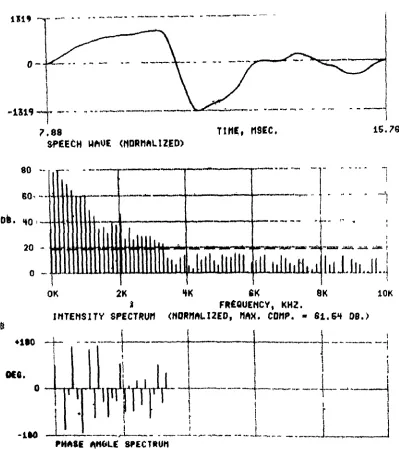
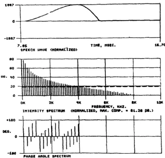
Figure
4 .
Wave Shape
and
Spectral
A n a l y s i s
of aTypical
G l o t t a l Wave
Period.The
intensity spectrum
has
been
normalized
sot h a t
the
largest component
is a t t h e 80dB
level;
beforenormalization
i t
was
61.54dB
relative
t oan arbitrary standard
of
0.25.
The
horizontal
line
across
the
i n t e n s i t y spectrum
graph
is
a
conservativelyestilpated
n o i s ecut
-offl i n e ;
any
com-ponent with
rnagnitudelless than
t h i s l e v e l maybe
the
product
of computational n o i s e .The
phaseangles
of t h ecomponents
are
gR,
where
t h e
wave
is
representedby
Z
A,
sin(nwlt+
vn)
and Q1
is
arbitrarilyzero.
Theexecution t i m e and
the
polynomial scored t h e h i g h e s ti n
h i stests of n a t u r a l n e s s . F i g u r e 5, page 14, shows t h e wave shape
and spectrum of a
l i n e a r
a p p r o x i ~ p a t i o n and F i g u r e 6, Page 1 4 ,shows
t h a t ofa
polynomial approximation. The o v e r - a l l f a l l o f fof t h e spectrum of t h e polynomial more n e a r l y matches our example
wave, b u t no l o b e s a r e a p p a r e n t , a s t h e y
a r e
i n t h e s p e c t r aof
the l i n e a r approximation and t h e n a t u r a l example. Judging
from some i n f o r m a l l i s t e n i n g t e s t s we have made, t h e s e
dis-
t i n c t i o n s do n o t seem t o make a g r e a t d i f f e r e n c e : b o t h approx-
i m a t i o n s sound good.
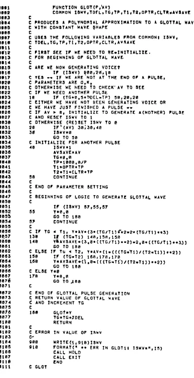
A s F i g u r e 7, page 15, we present
a
F o r t r a n f u n c t i o nGLOT(P,AV)
for g e n e r a t i n g g l o t t a l waves u s i n g €he polynomialapproximation. Values of p i t c h ( P ) and zero-to-peak amplitude
(AV)
a r e p a s s e d d i r e c t l y a s c o n t r o l parameters.The s u b r o u t i n e u s e s t h e common a r e a t o s t o r e s e v e r a l v a r i a b l e s ,
which
o r c o u r s e c o u l dhe
d e c l a r e d a s formal parameters i n s t e q d ,ISWV
i sa
v o i c i n g switch used i n t h e l o g i c i n t e r n a l t oGLOT.
TDEL
i s t h e p e r i o d between o u t p u t sample p o i n t si n
m i l l i s e c o n d s ;i n t h e over-all i n i t i a l i z a t i o n of t h e program, i t s v a l u e should
be
c a l o u l a t e da s
1000.0/OSR. where OSR i s t h e o u t p u t samplerate
i n
samples per second. TG i s a v a r i a b l e useda s
a s i m u l a t e dt i m e clock by GWT, keeping
track
of how f a r t h r o u g h t h e g l o t t a lwave
i t
has gone.TP, TI,
a n d T2a r e
d u r a t i o n s ( i n millisecond^)from t h e hegirining o r the g l o t t a l p u l s e , c a l c u l a t e d and used by
GLQT:
TP
i sthe
d u r a t i o nof
t h e pulse.T1
i s t h e d u r a t i o n oft h e opening phase, and T2 i s t h e d u r a t i o n of the opening and
--
PHASE M O L E SPRCTRUWFigure 5. Wave Shape and Spectral Analysis of a
L i n e a r Approximation to a G l o t t a l Wave. For
details of
the
display, cf. Flgure 4 .la07
4 0 8 7
7 . 8 6 trm, nrac. s.70
$ P & c ~ H UhU6 < U O R P M ~ Z L O ?
Figure 6. Wave Shape and Spectral Analysis of a Polynomial Approximatioa to a G l o t t a l Wave. FOX
Figure
ruNevxaN CLOT ( P , ~ A V )
COMMON ~ ~ u V ~ T D F L ~ T G ~ T P , ~ ~ , T D ~ O P T R ~ C L T R ~ A V ~ A V E C
C PRODUCES A P O L Y N O M I A L 4 P P R O X I H A T f O N TO L G L O T T A L WAVE C W I T H C O N ~ T A N T WAVE $HAPf!
c
c uacs THE ~ O L ~ O ~ X N G V A R I A R ~ E ~ man COMMONI X S W V , C T D f C ~ T C , t P , T l r T 2 , a P T R , C L T R , A v 1 A V t ;
C
C P l R 8 T 8EC I P HI! NEED TO R L m I N I I I A L I t L ~ C F O R B L G f N H l N G OF G L b T T A L H A V E
C
C ARC W t HOW GENERATING V O f t E T
r r ( X ~ M V I ~ B E , I ? ~ , { ~
c Y E S
-.
3 1 HE A R E N O T A T THE END o r A r u L a C ,C PARAMETERS ARE OeK,
C OTHERWl3E Y E NEED TO C H E C K ' A V Tb SEE
c xr HE N E E D ANOTHER PULSE
1 0 I F I T G + 0 , 5 * W E L - T P ) 5 B 1 2 8 p 2 0
C E I T H E R H E HAVE NOT BEEN G E N E R A T I N G V O I C E OR
C WE HAVE JUST FINISHED A PULSE r r
C I F ' AV P 0 , X N I T I A L X Z E TO GENERATE A(NOTHER] P U L I L C AND R E S E t I S Y V TO 1
C OTHERWISE ( R E j 8 E T I S H V TO B 28 I P * ( A v ) 3 0 ; 3 0 , 4 0
3d 2Suv.a
G O T O 5 0
C I N I T I A L I Z E FOR ANOTHER P U L S E
48 I S W V l l
h V S A V E 8 AV
t6aB.B
TP.lB0BeG9/P T l m O P T R t T P T S m T l * C L t R * T P
58 C O N T I N U E C
C END O f PARAMETER S E T T I N G
c
c BEGINNING OF L ~ G X C T O GENERATE G C Q T I A L W A V E C
I F (IJWY) 5 7 1 S 5 t 5 7
55 Y.R18
t o t o 1 0 8 5 7 C O N T I N U E C
C fr TG T I , Y . A V * ( ~ * ( T C / T ~ I ~ * ~ - ~ + ( T G / T ~ ] * * J )
138 I.# (TG.Tll 1 4 8 , ) S A P 15R
149 Y ~ A v S A V E * ( J , B * ( [ T G / T l ) * * 2 ) - 2 , 8 * ( ( T C / t l ) c * 3 ~ ) GO 70 180
C ELSE I F T S * 7 2 , Y ~ A V * ( l ~ ( ( ( T G ~ f l ) / ( T 2 ~ T l ) ) * * 2 ) )
159 I F ( T G * T 2 ) 1 6 G 1 1 7 8 a 1 7 B
c ELSE rue
178 Y.fl,fl
GO T O A 8 0
c
C E N 0 OF GLOTTAL PULSE GENERATION C R E T U R N VALUE OP GLOTTAL N A V E
d AND XNCREHENT TG C
189 G ~ O ~ D Y TG.TG+JtIEL REYURN
C
c E R R O R IN V A L U E OF x s r v
C-'
900 U R ! T E ( I , 9 i @ ) 13UV
0 1 0 FORHAT("* ERR I N G L D T l l ~ ~ Y v R ~ ~ , I ! J )
CALL HOLD C A L L E X I T
€ N O
C GCOT
r a t i o " ) i8 t h e tractlon
or
tne waveo a c u p l e a
by The openingphase,
and
CLTR
i sthe
fraotiono c c u p i e d
byc l ~ c r i n g .
I n
t h eover-all
i n i t i a l i a e t t i o n ,OPTR
ehouldbe
set t o.40
and
CLTR Lo
.16, v a l u e swhich maximize naturalness
according to Rosenbergfs paper.S f
t h e i n s t a n t a n e o u s values of A\I were used by GLOT, thestandard,
wave shape would be altered ifAV
were changing duringgeneration
of
a
g l o t t a l
wave.
To keepthe
waveshape
constant,GLOT
uses the variable AVSAVE t oa t o r e
t h e value of AVat
t h eb e g i n n i n g of each p i t c h period,
and
duringthe
generation oft h e
pulse,AVSAVE
is
usedas
the
(constant)a m p l i t u d e .
Between c a l l s t o GLOT,
the
values ofIsmt
TG,
TP,
T1,
T2,and
AVSAVE s h o u l d n o t be altered,Rosenbergls equations for the polynomial approximation
a r e used
in
GLOT; to getthe
linear approximation, the follow-ing
two
l i n e s of F o r t r a n s h o u l d be substituted in GLOT forlines number
60and
64:2 . White Noise Generator
Almost any reasonably good random-number generator c a n be u s e d a s
a
s o u r c e of white n o i s e .If
t h e spectrum of t h erandom numbers produced is f l a t ,
it
w i l l be e a s i e r to shapeinto the desired spectra fox
the
d i f f e r e n t fricative sounds.The algorithm w e use was developed f o r use i n s y n t h e t i c
speech work: i t i s v e r y fast, a n d produces noise with
a
quiteand p e r r y l i s easy to f e l l o w and implement. The l o g i c of t h e
algorithm i s f o r m a l l y stated
i n
F o r t r a n in Figure 8 , page 1 8 ,but if possible this s h o u l d be one function coded
in
alssemblylanguage: if the right machine instructions are available,
it
w i l l be snap, b u t "bit i n F o r t r a n is very s l o w .Our function
IRN4(X)
- -
X
is a dummy variable requiredby our F o r t r a n compiler
- -
contains this algorithmin
assemblylanguage, producing on successive calls a series of random
numbers
with
a uniform distribution overthe
interval from-2047 ta +2047.
To
implement a white noise g e n e r a t o r , o n l y t h i s line of coding i s needed:where
AN
is a variable whose value is the amplitude of n o i s edesired.
A
typical stretch of noise produced in this manner, alongwith i t s spectrum, i s g i v e n a s Figure 9, page 19. Note that
there does not appear to be any significant deviation from
flatness
in
t h e spectrum intensity.B. Spectral Shaping E l e m e n t s
1. Resonances and Anti-resonances
We use recursive equations, a technique developed by
electrical engineers, to simulate resonant. and anti-resonant
( n o t c h ) filters a s elements to shape spectra. Each individual f i l t e r can be represented by a second-order linear differential
1. R a d e r , Rabiner and Schaf er (1970) and P e r r y , Schafer.
FUNCTION
IRN4(X)COMMON
N M 1 ( 1 9 ) ,NM2(19)
DlMENsION
NX1(19),NX2[19)
C
FORM
BIT-WISE
EXCLUSIVEOR
OF
NMl,NM2
DO
10 I=1,19
10
~ X l ( f
)-MOR(NM1(1:),NM2(I)
C
ROTATE NXI,
8PLACES
TO
TI.B
RIGHT
DO
20I=l,ll
20 NX2
(I+B)=NXl
(I)
DO30
I=12,1930
NX2(1-11)=NXl(I)
C SHIm PAST VALUES
DO
40 I = l , 1 9
N M 2 ( I ) = N M l ( I )
40
N M l ( I ) = = N X 2 ( I IC
RETURN VALUE
OF
LEFT-MOST
1 2BITS
OF
NX2
IRN4=MINT(PfX2)
C END
]HETURN
END
Figure 8. Random
Number
Generator DocumentedIn
k ' o r t r a n .NMl(19) and
NM2(19)
are! a r r a y s
whose e l e m e n t s have e i t h e rt h e v a l u e 0 o r 1.
MOR(Nl,N2)
is afunction
returningthe
exclusive
or ofN1
and
N2,
v a r i a b l e s h a v i n g e i t h e r t h e v a l u e0 or
1.
MINT(N)
isa
function
whose argumentN
is abit-
80
80
'to
20
F i g u r e
9.Typical
Wave
Form
and
Spectral
Analysis
of
t h e Output
From
t h e White
Noise
Generator.
[image:19.786.197.626.279.746.2]e q u a t i o n , g i v i n g only
one
resonanceo r
anti-resonance. FOX thosewho f e e l a t home i n
the
s-plane,the
r e c e n t book 8p?.eCh --Synthesis
. ---edited
by Flanaganand
Rabiner contains rsprinta ofpawrs
d e v e l o p i n g
the
theory of r e c u r s i v e equation f i l t e r simulation:for t h e
rest
of us,the
paper by Lovell et al. (1973) i s a c l e a rpresentation,
with
some moreg e n e r a l
F o r t r a n algorithmst h a n
w i l l be given here.
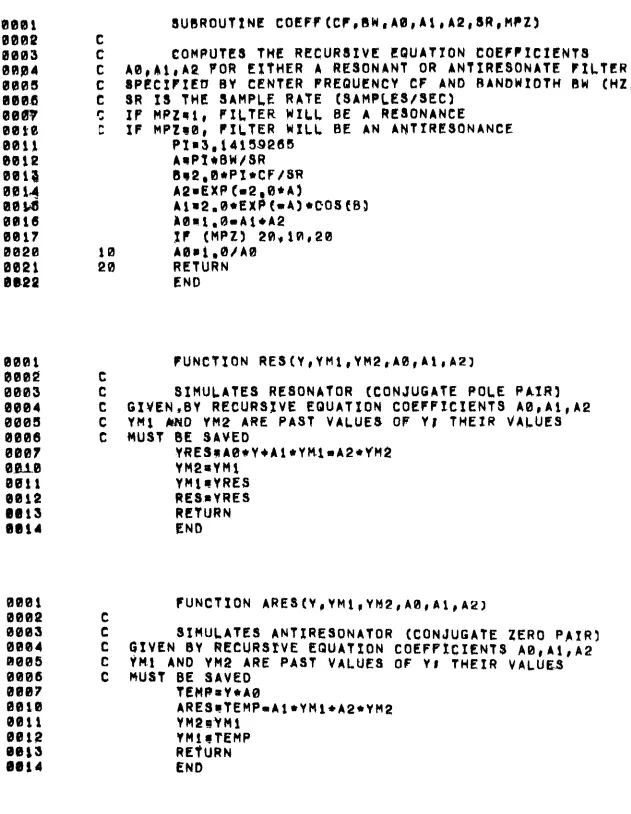
Figure 10, Rage 21, g i v e s one Fortran s u b r o u t i n e and
two
Fortran f u n c t i o n s which we use t o simulate r e s o n a n t a n danti-resonant t l l t e r 8 .
The
f u n c t i o n s RE3 and ARES r e t u r n the output v a l u e s ofsimple resonant ( c o n j u g a t e pole p a i r ) and a n t i - r e s o n a n t (con
jugate z e r o p a i r ) f i l t e r s . respectively.
AO,
Al,
and A2 arecoefficients used
in
the r e c u r s i v e e q u a t i o n s .I
and Y'M2 axeremembered previous
values
of t h e signal, and Y is the i n p u tt o the filter.
AO, Al,
andR2
determine t h e characteristicsof the filter: c e n t e r frequency and bandwidth. Each s i m u l a t e d f i l t e r s h o u l d have i t s own v a r i a b l e s i n which t o save t h e values
of
YM1
and YM2, and between calls to the fdnction simulatingthat f i l t e r , t h e values of these variables ahould not be changed.
The
subroutine COEFF is used to c a l c u l a t e appropriatevalues for
AO,
Al,
and A2, b a s e d on CF, the c e n t e r frequency,and
BW,
t h e bandwidth. of the r e s o n a n c e or anti-resonance. 1SR
isthe
output sample rate, and MPZ tells t h e subroutine1. I n
the
v e r s i o n of this paper presented atthe
12th annual~ U B R Q U T X N L
~ o ~ e ~ c c r , a w , ~ s , r r , ~ a , s ~ , ~ r z ~
CC! COMPUTE8 THE R ~ C U R b I V E E Q U A T I O N E Q E F P X C I E N T 8
C A 0 , A I I A Q FOR EXf'HER A RESONANT O R AN'TIRPBONATL P I L T C R
C ~ I P E C ~ $ ' ~ ~ U 0Y CENTER FRl!!OULNCY C F AND BANbWtOTH I W (HZ.)
C 8R 1 8 THE SAMPLE R A T E ( ~ A M P C E S I ~ E C }
S I P W P L q I , F I L T E R W I l L BE? A RPIONANCE
C I F M P Z 8 0 , C X L f E R WILL BE AH A N T T R C B O N A N C E ? X ~ 3 , t 4 1 5 9 Q 6 6
AaPXlrcBW/SR
Bs2,8*PI*CP/SR
A O ~ E X P C m 2 , B * A j
A ~ ~ & , B + E X P ( a 4 1 +CO5 CB3 & 0 m l n B r A 1 + A 2
I F (MPZ) 2 f l u l f l r Q 0
1 0 A O @ l , B / A B
20 RETURN END
Q U N C P I Q N R E S C Y t Y M 1 1 Y M 2 r A 0 , A l r a 2 ] C
C SIMULATES R E 8 0 N A T O R (CONJUGATE POLE P A I R 1
C GXYENpBY R E C U R S I V E E Q U A T I O N C O E F P Z C I E N T S A B P A 1 , A 2
C Y M i khlD V M 2 ARE PAST VALUE$ OF Y I T H E I R VALUES
C MUST BE SAVED
YRESrnABtY+Al * Y M ~ u A ~ * Y M $
YM2aYMt
Y M t r V R E S
ISESrVRES RETURN END
F U N C T I O N A R E J ( V ~ Y M I p Y M 2 , A 0 1 h l C A 2 J
C
C S I M U L A T E S ANTIRESONATOR (CONJUGATE Z E R O P A I R ]
C G I V E N BV R E C U R S l V E E Q U A T I O N C O L f P f C I E N 7 9 A B , A i , A 2
C Jn! AN0 Y M 2 ARE P A S T VALUES OF Y t T H E I R V A L U U
C MUST BE SAVED
TEHPaY+A0
ARESeTEMP*Al*YMl*A2+YM2
YMZ!3YMf
Y M l r T E M P
[image:21.786.69.700.121.935.2]RE*~URN END
whether to compute ~ o e f f i ~ i 0 n t ~
fsr
B rasonancs or a n a n t i -XBEI onance
The s p e c t r a l e f f e c t of a resonance with center frequenay
of 3000 H e a n d bandwidth of 200 Ha is i l l u s t r a t e d in Figure 11,
page 2 3 , while F i g u r e 1 2 , page 2 3 , is a similar illustration of
the, e f f e c t sf a n anti-resonance of t h e same c e n t e r freq'uency
and bafidwidth. I n these figures, t h e f i x s t g r a p h shows o u t p u t
for a n impulse input and t h e second graph shows t h e normalized
intensity spectrum, of t h a t o u t p u t .
2 . R a d i a t i o n E f f e c t
The e f f e c t ~ o n t h e s p e c t r u m o f , t h e radiation of s o u n d from
the l i p s through a s h o r t stretch of air c a n be reasonably approx-
imated by a differentiat0r.l Figure 13,- page 24, gives a s i m p l e
F o r t r a n f u n c t i o n
KAD
s i m u L a t i n g t h i s e f f e c t . Y is t h e s p e e c hm v e i n p u t t o t h e s i m u l a t e r ,
YM1
is the remembered immediatelyprevious value of
Y,
hfid G i s a n o r m a l i z i n g gain c o n t r o l whichshould be c a l c u l a t e d i n t h e over-all i n i t i a L i z a t i o n a s a d i r e c t f u n c t i o n of the output s a m p l e xake, some
K
t i m e s OSR. The s p e c - t r a l e f f e c t of RAID, approximately a 6 dI3/octave rise, i s i l l u s -t r a t e d i n Figure 1 4 , p a g e 2 4 .
IV.
Organization of ElementsA. The Simplest Model
The simplest r e a s o n a b l e model f ~ r c o n n e c t i n g t h e s e elements,
which we have t a k e n t o c a l l i n g "Mode3
TI',
fs given i n b l o c kdiagram form i n F i g u r e 15, page 25.
We
use this o r g a n i z a t i o nIn o u r c u r r e n t l y ru'nning synthesizer. T h e t h r e e vdriable
-.
...-.-
"r""- * " " +----a--2011 -. *I--
----
.,---~ 1 . m mrc. 28.11
I
[image:23.786.214.589.112.464.2] [image:23.786.223.601.556.901.2]t r e a c ~ unvc <nounn~ t ZED)
Figure
11.
Spectral Shaping E f f e c t ofan
Elemental Resonant F i l t e r with CF=3000 'Hz and BW=200Hz.
R A D ~ O * ~ Y I Y M I I
Y M l n Y
RETURN END
F i g u r e
13.
F o r t r a n
Function
toSimulate
RadiationEf
feat.OU 2K YK BK 8% low
FREQUENCY, K H z .
[image:24.786.190.596.516.898.2]~ W T L ~ ~ ~ Z T Y ~ C E C T R U H ~ W ~ R ~ ~ L I Z E D , nhx. camr. r a+. 7 6 or.,
Figure 14.
Spectral
Shaping E f f e c t of Radiationresonant
f i l t e x s are used to make t h a f o r m a n t s o f v o i a a d speech and, i na rather
strainedfashion, to-
shapethe
noise spectrumduring frication and aspiration.
A I L of t h e elements in this figure
should
now befamiliar
except
the
onecalled
"higher otder correction filter.^^ This isa s e r i e s of resonant filters of fixed center frequency and
bandwidth
which
cornpensat e forthe
effectof
higher -f requencyresonances present in
a
real vocal tractbut
absent in a d i g i t a lsimulation of t h i s kind. Their
use
is discussedin
Rabiner ('1968.)from
which
the values presented in Figure 16, page 27, were taken.These are the values to use for center frequency and bandwidth of
t h e higher order correcting f i l t e r s . O n l y higher-order f j l t e r s
with center frequency less t h a n
&
khe output sample rate should beused. The x e c u r s i v e equation c o e f f i c i e n t s AO, Al, and A2 need be
calculated only once, in the over-all initialiaation.
Theoretically, the arder o f computation of the s e r i e s elements
such a s those in the main stem of Model
T,
makes no difference.However,
because thedigital
numbers are finite in length round-offor truncation errors are introduced a t each s t e p of' t h e computation
The overall error increases as the number o f computational s t e p s
increase. Some types o f computation such as differentiation tend
to increase the error, while other types such as integration tend
ro aecrease - m e e r r o r . F o r this reason, overall system error is
related in a complex way
to the
order of computation.An
understandinof
error buildup and testing ofthe various algorithms will
help inchoosing
the
computational sequence that results in smallest errorsIn the case of cascaded resonators. it is better to perform t h e
computation
in
reverse order from t h a t implied by Fig.15
-
radia-t i o n e f f e c t
first,
thenhigher
order filters in descending centerResonator
No.
Center
F r e q .(Hal
Bandwidth
(Hz)
Figure
16.Higher
OrderCorrection
F i l t e rCenter
Frequencies
and
Bandwidths.
F r o m Rabiner(1
968)C
ZERO
VARIABLE
HOLDINGNEXT
SPEECH
WAVE P O I N TYN=O
- 0C
ADD
GLOTTAL WAWYN-YN-tGLOT (
P,
AV)
C
ADDFRICATIVE
NOISEYN=YN+AN*(FLOAT(IRN4(X))/2047mO)
C
-PLY
FORMANT F I L T E R SW
200 I = 1 , 3200
YN==S(YN,ml(I)
,YM2{IJ,AO(I)
,Al(I),A2(I)
1
C APPLY HIGHER ORDER CORREZTING FILTERS
DO 2 5 0 I = l , 7
250
Y N = R E S ( Y N , ~ ~ ( ~ ) , ~ ~ ( I ; ) , H A O ( I ) , H A ~ ( I ) . ~ ~ ( I )
CaAPPLY
IRADIANCEEFFBCT
YN=RAD(YN,
RYM1, GRAD)The c o n v e r s i o n of t h e Model
T
b l o c kdiagram
into F o r t r a n isi l l u s t r a t e d by
Figure 1 7 , page
2 7 , t h eseries
elemel~ts beinghere
computed
i n
t h e i rnatural
o r d e r . T h i s codingi s
an
example
of
what
should be i n s e r t e di n t o t h e
o v e r - a l l
logic( F i g u r e 3,
page 9 ) f o l l o w i n g t h e comment l i n e s "GENERATE
NEXT
SPEECHWAVE
I I
POINT.
,. .
B.
Control
I n
t h e ModelT
o r g a n i z a t i o n , n i n e c o n t r o l p a r a m e t e r s a r ea v a i l -
able
- -
P ( p i t c h ) , AV (amplitude of v o i c i n g ) , AN (amplitude of noise)and the
center
frequencyand bandwidth
of
three
variable
formant
f i l t e r s .
I n
t h emain
l o o p , just before generating the next speecnwave
p o i n t ,a
s u b r o u t i n e ( i tcan
bein-line
code, of course)calcu-
l a t i n g
v a l u e s
of these p a r a m e t e r s i s needed.If
a tthe
beginningof
the
program t h evariable
T ( t i m e ) i s i n i t i a l i z e d t o zeroand
lncremented byTDEL
a t t h eend
ofthe
main loop,it
can serveas a
simulated-time clock
onwhich
to basec a l c u l a t i o n
of t h e ,c o n t r o l p a r a m e t e r s . The s i m p l e s t method of c o n t r o l is
t o
formu-include Fortran
statementsin this
sedtion calculating their v a l u e sas
inthe
algebraic equations. For example, supposewe
mnted
the
pitch t o rise linearlyfrom
80 to 120Hz
in
t h e f i r s t100 msec, stay constant at 120
Hz
for 200 msec, thenfall
linearlyt a 100
Hz
inthe
next 100 msec and stay at that value fromthen
on.The
following Fortran statements can be used to calculateP:
6 0
TO
270260 P=lOO ,O
270 CONTINUE
When new v a l u e s of CF and
BW
are computed forthe
t h r e e variable formant filters, subroutineCOEFF
should be called totranslate these into the coefficients
AO, Al,
andA2
actuallyused by function RE$.
If
n e w valQes of thi c o n t r o l parameters are c a l c u l a t e d e v e r ysample point,
the
execution time of the program w i l l be very longThere ape s e v e r a l obvious ways t o speed up this calculation.
One way
is
to calculatenew
values for P andAV
only atWith
some
e r r o rintroduoed.
the
control
parameterscan
be
re-computed
o n l y everyso
many
meeo
t ospeed
t h i n g sup.
A
variable
used a sa
timeclock
i nthe
same
waythat
TG
is usedby
GLOT
cancontrol
this
period. Computing the
sourcecontrol
parameters ( P , AV, and
AN)
t h i s wayintroduces
erroronly in
that
the
a c t u a lparameter
c u r v e s w i l lfollow the
desired c u r v ein
ss t e p - w i s e f a s h i o n , b u t
changing the characteristics
of theformant f i l t e r s
this way
will
introduceanother
type of e r r o r ,which
comes
outsounding like
c l i c k sor static
i fthe
changein
filter
characteristics i s t o olarge.
Our
c u r r e n t l y - i m p l e m e n t e d a ~ s e m b l y - l a n g u a g esynthesizer
reads
a
f i l ' e oftabled
v a l u e screated
byanother
program asvalues
representing the
parameter curves. The period betweent a b l e d parameter v a l u e s is
changeable,
but on the orderof
5to 1 0 msec. I n
computing the actual parameter values
used, t%esynthesizer interpolates
linearly alongthe tabled parameter
datacurves.
The step size
ofthe interpolation
can beeasily
changed,allowing
a
smooth trade-off between accuracy
and execution time.To sum up,
computing
new control parameter values f o x each samplepoint generated
is the easiest and most accurate way, butalternative
schemesallowing a convenient trade
of accuracy forspeed are easily
programmed
C.
Other Models
We
will
briefly describe severalalternative organizations
of the
elements, although
most of ourpractical experience has
1,
P a r a l l e l FormantOne model used
i n
some s y n t h e s i z e r s l a t h e p a r a l l e lformant
model, whose
blockdiagram
i s given a s F i g u r e 18,page 3 2 .
In
serial formantmodels
such as ModelT,
no
independent c o n t r o l of t h e r e l a t i v e
i~teensities
of formantsi s p o s s i b l e ,
since the
order of o p e r a t i o m i s i m m a t e r i a l . I thas
been shorn t h a tt h e
relative intensities
of f o r m a n t si n
a
serial
s v n t h e s i s c l o s e l y match t h o s e foundin
n a t u r a l speech,1
which i s some j u s t i f i c a t i o n of t h e
serial
model a s a n analogof t h e vocal t r a c t . But
i n
a p a r a l l e l formant arrangement, eachparallel
channel musthave
a separate gain c o n t r o l . T h i s i s finei f v o u l r e i n v e s t i g a t i n g
the
perception of r e l a t i v eformant
intens-i t i e s , b u t n o t many have chosen t h i s model for general speech
synthesis
Rabiner
( 1 9 6 8 ) c o n t a i n s a worthwhile d i s c u s s i o n ofthe
r e l a t i v e merits of
serial and
p a r a l l e l synthesis. I f you decidet o try
a
p a r a l l e l formant model, t h e h i g h e r order c o r r e c t i n gf i l t e r s
are
apparently unnecessary,and
Rabiner (1968 ) mentionsthat z e r o s
- -
anti-resonances- -
a r e introduced into t h e spectrum.2. Separate Noise Shaping Channel
In
ModelT,
the sqmethree
f i l t e r s are used t o make theformants ot v o i c e d speech and to shape t h e spectrum of noise
during unvoiced speech.
This
is cumbersomeand
d i f f i c u l t , anda
simple alternativeis illustrated in
F i g u r e 19, page 34.1. Fant
( 1 9 5 6 )I
GLOTTALWAVE^^
A V
RADIATION
EFFECT
.
11 I
[image:32.786.71.713.261.695.2]h - .
Figure 18. Parallel Formant Organization Model
RESONANCE
-
CF1 RESONANCE -CF2NO, 1
-
NO. 2BW1
m L
*
RESQNANCE
NO.
3
-
-
CF3A separate
channel
ie devoted tonolae,
with i t sown
r e s o n a n tand
anti-resonant filters for
spectralshaping.
It
haa been
suggested
that
one remnanceand
oneanti-resonance
axesufficient
to nodel
m e $
English
f r i c a t i v e s .1
O fcourse, this model
addst w o
new control parameters
t abe computed.
3 .
Other More Complex Models
Model
T
does not
useanti-resonances;
they are
not
typicalo f
voiced speech, but
rather
are present
in
the spectra of
faicatives
and
nasalized segments.
For
making nasal sounds,
a
parallel nasal channel whose input is the glottal wave and whose
output
is added
in
just
beforethe
radiance
effectcalculation
can
be added.
The
spectral
shaping filters needed in this channel
are not obvious from published reports,
but one variable anti
-
resonance and several
fixed resonances are
p r o b a b l ya
m i n i m u mcomplement.
A
multitude
of more complexmodels
canbe seen
in the litera-
ture,
- -
Rabiner (1968).
totake
oneexample, includes a
speciala'rrangement
for generating
voicedfricatives.
D. A Complete
ExampleTo i l l u s t r a t e
the capabilities
ofthe ~implest
synthesismodel,
on the following pages we p r e s e n t a s Figure 20 a completeFortran program
forsynthesizing
the
wrdllseatll
(sith]
) .We tried to
duplicate one particular token
utteranceof, this word.
Spectrograms
ofthe
o r i g i n a lsound used
a s
a modeland
thesyn-
thesized sound calculated by the
Fortran
program are shown in
-- --
GLOTTAL WAVE
PARAMETERS
RESONANCES VOCAL TRACT
PARAMETERS-
[image:34.786.73.713.284.729.2]NTI-RESONANCE-
Figure 19. Block D i a g r a m of Model With Separate
Figme 21, page 44. D e r i v i n g
the
parameter curvQa fromthe
token utterance took
a
l o t of work, b u t as Figure 2 1 shows, t h erssulkihg ~ l y n t h e t i c
word
i s a r e a s o n a b l y close copy of the o r i g i n a l .F o r those who may want t o use, this program as
a
beginning totheir
work, s e v e r a l features ofi t
w i l l be explained.The basic model used i s
the
simplest, model W"f (Figure 1 5 ,page 25) w i t h one a d d i t i o n : t h e noise s i g n a l i s m u l t i p l i e d by a
relative
gain c o n s t a n t(GFRIC)
b e f o r e e n t e r i n g t h e vocal t r a c t( v a r i a b l e
filter)
s e c t i o n .The output sound wave i s s t o r e d a b l o c k a t a t i m e in f i l e
WWRK1. T h i s file is opened by t h e s u b r o u t i n e c a l l e d i n l i n e 43
w r i t t e n into i n line 455, and c l o s e d i n line 470.
Parameter v a l u e s a r e p e r i o d i c a l l y c a l c u l a t e d from piece-
w i s e polvnomial algebraic speciffications i n the section c a l l e d !lGPARfI, l i n e s 142 t o 415. The periods between p a r a m e t e r
r e - c a l c u l a t i o n s a r e c o n t r o l l e d by twa v a r i a b l e s serving a s
clocks, TVOC for v o i c i n g parametexs and TFRIC f o r f r i c a t i o n
p a r a m e t e r s . The values of PVOC and PFRIC are t h e t i m e s i n msec
between r e - c a l c u l a t i o n s of vocalic and f r i c a t i v e parameter v a l u e s ,
r e s p e c t i v e l y . These parameter v a l u e s can be reset more often by
merely changing t h e values assigned to PVOC and PFRIC i n l i n e s
9 3 and 37; a t present f r i c a t i o n parameters a r e reset every
0 . 1 msec and v o c a l i c p a r a m e t e r s e v e r y 0 . 2 msec. The F o r t r a n
logic calculating the parameters was coded for c l a r i t y , not econ-
omy, and though lengthy should be easy t o f o l l o w . The primitive
s u b r o u t i n e TPOW r e t u r n s pawrs of
a
v a r i a b l e f o r e a s e in c a l c u -Certain paramaters are c o n s t a n t d u r i n g aome o f the sounds,
e . g . , s p e c t r a l parameters during f t 3 f N . As
a
minolr concession to exeoution speed, t h e s e constant parameters are not reset a f t e r the f i r s t entry into t h e section d u r i n g which t h e y are constantThe variables 19W1, ISW2, and 1SW3 a r e irst-time-through"
s w i t c h e s , used t b remember whether or n o t the tempora1:il.y
constant parametei-s have h e n calculated y e t .
We have found that duplicating a token of natural speech
u s i n g t h L s simple basic synthesis model, t h o u g h p o s s i b l e , can
be q u i t e d i f f i c u l t , r e q u i r i n g much trial-and-error work.
F o r t u n a t e l y , much r e s e a r c h on speech perception does not r e q u i r e
exact duplication of g i v e n u t t e r a n c e s , b u t i n s t e a d uses simpler
sets of parameter curves. An example of such a program, which
synthesizes the v o w e l /it with constant p i t c h a n d i n t e n s i t y can
be made by substituting t h e following code for t h e "GPARfl Section, lines 151 t o 411 of' t h e sample program.
IF
(ISW1) 150,100,150I S W l = l
P=lOO. 0
AVDB-15 0 . 0
A V = = ~ O . O ~ * ( A V D B / ~ O . O )