Using Functional Design Patterns to improve Exports to
Management Information Systems
Barry Nijkamp
Abstract
Software developers increasingly use patterns to improve the quality of the software they produce. These patterns help improve the reusability of both the design and the
implementation, and decrease the amount of errors made. Next to well known software patterns for code, patterns for functional designs have been developed. Exporting data from a production system to a Management Information System occurs in many systems and the functional design of these exports contains similar elements. In this research, these similar elements are combined into a functional design pattern. This functional design pattern is then used and evaluated. The result of this evaluation shows that a functional design pattern can be created for the export to Management Information Systems, and that the pattern is useful. However, the pattern is large and another method to store the knowledge might be more applicable.
Version history
Date Version What01-06-2008 0.1 First version
07-08-2008 0.2 Moved working copy to MS Word
First version of time dependency
13-08-2008 0.3 Changes according to meeting with Quinity 11-08-08
21-08-2008 0.4 Changes according to meeting with Quinity 18-08-08 Added chapter 4– Methods to export history
08-09-2008 0.5 Changes according to meeting with Quinity 01-09-08
Changes according to meeting with M. Fokkinga 05-09-08
15-10-2008 0.6 Updated to reflect changed in patterns
20-11-2008 0.7 Changes according to meeting with M. Fokkinga 18-11-08
20-01-2009
26-03-2009 0.8
Validation performed and described.
Finalised report for complete review.
02-04-2009 1.0 First version ready for review
Sent to all supervisors.
03-05-2009 1.1 Updated according to remarks from supervisors.
05-05-2009 1.2 Added chapter ‘Conclusion’.
07-05-2009 1.3 Finalised report. Sent to all supervisors.
Contents
1. Introduction ... 6
1.1. History of patterns ... 6
1.2. Types of Design Patterns... 6
1.2.1. Technical design patterns ... 7
1.2.2. Functional design patterns... 7
1.3. Problem statement ... 8
1.4. Research question... 8
1.5. Method ... 9
1.6. Related research ... 10
2. Management Information Systems... 11
2.1. Context ... 11
2.1. Structure of a Management Information System ... 12
2.2. Queries on a Management Information System ... 15
2.3. Operations on Management Information Systems’ results ... 16
2.4. Using a Management Information System... 16
2.4.1. Analysis of current situation ... 17
2.4.2. Analysis of past trends ... 17
2.4.3. Prediction of future, when nothing changes... 17
2.4.4. Prediction of future, when something changes ... 17
2.5. Methods to fill a Management Information System... 17
2.5.1. Continuous stream... 18
2.5.2. Batch... 18
2.6. Exporting to a Management Information System ... 18
3. Data in Production Systems ... 20
3.1. Context ... 20
3.1.1. Insurance Company... 20
3.1.2. Book Seller ... 21
3.2. Data types in production systems... 21
3.3. Properties of data in production systems... 22
3.3.1. Amount of additions... 22
3.3.2. Amount of changes... 22
3.3.3. Type of history in production system... 22
3.3.5. Is meta data... 23
3.4. Time dependent data ... 24
3.4.1. Reading valid data ... 24
3.4.2. Referencing valid data... 24
3.4.3. History and time dependent data ... 24
3.4.4. Second dimension of time dependent data ... 25
3.5. Exporting data ... 30
4. Requirements... 31
4.1. Requirements on production system ... 31
4.1.1. Detecting changed items ... 31
4.1.2. Handling deletions... 32
4.2. Requirements on Management Information System ... 32
4.3. Requirements on exported data ... 32
4.3.1. No history in production environment ... 33
4.3.2. Change history in production environment ... 34
4.3.3. Version stack in production environment ... 35
4.4. Requirements on the export... 36
5. The pattern ‘Export to MIS’... 38
5.1. The pattern ‘Tracking changes’... 38
5.1.1. Tracking changes using a flag or timestamp ... 38
5.1.2. Tracking changes using a detection table... 39
5.1.3. Detecting deletions ... 40
5.2. Elements of pattern ‘Export to MIS’... 41
5.3. Relation to the requirements ... 42
6. Evaluation... 43
6.1. Method ... 43
6.2. Results ... 43
6.3. Discussion ... 44
7. Conclusion... 45
7.1. Research ... 45
7.2. Future research ... 45
7.3. Using functional design patterns ... 45
7.4. Final words ... 46
Appendix B - Functional Design Pattern ‘Tracking changes’Appendix C - Functional design ‘Export from policy administration to MIS’ ... 49
1. Introduction
This section gives an introduction to design patterns, both functional and technical, and Management Information Systems in general. A short history of patterns will illustrate the use of them in the software development process, while the overview of the uses of a
Management Information System and the advantages they offer will show the need of exports to such a system. The goal of this research is to find and evaluate a pattern in the designs of export functions of production systems to a Management Information System.
1.1. History of patterns
Today’s patterns are widely used in the software development, both in the design and implementation phase. The concept of patterns has been adopted from another designing profession, the building architecture. Christopher Alexander, an architect for buildings, observed that historical cities are attractive and harmonious [Ale77]. Alexander and his co-authors credit the local regulations of medieval cities for creating a kind of pattern that required certain features, but gave the builders the freedom to change them according to the situation. The writers abstracted these regulations into a more generic practical architectural system of patterns. These patterns could afterwards be used to increase predictability and speed up the architectural design.
The real introduction of patterns in software design was in 1987 at the OOPSLA conference. At this conference, Beck and Cunningham presented their findings on their experiments applying design patterns on the software development process [BC87]. A number of
researchers continued working on the idea of patterns, but the real breakthrough was only to happen in the mid-1990’s, when Gamma et al. published a book about common patterns in software architecture. In this book [GHJV95], the authors defined twenty-three patterns and described them in a structured and detailed manner. This publication is seen as the basis of the use of patterns in the current software design. Almost all of the patterns defined in the book can still be and are used in software designs today.
Fowler [Fow96] defines another group of patterns, the analysis patterns. These patterns are not primarily focused on the design process, but try to give an analytic view of phenomena. This means the functional behaviour is analysed, which makes them comparable to the functional design patterns which will be discussed later. However, analysis patterns focus on the business process that is hidden in the design, while functional design patterns try to capture the generic functionality. Reyngoud and Van Helden classify the analysis patterns as “conceptual patterns according to the classification of Riehle and Zullighoven, since they do not discuss technical architectures or implementation, but regard the concepts of a specific application domain” [vHR05]. We will not discuss further details about analysis problems, because the business logic is not important in the export of data to a Management Information System.
1.2. Types of Design Patterns
In software development, patterns are often used. Many software projects use patterns to store knowledge on recurring features. Because a lot of different patterns exist today, patterns are split up into a number of pattern types.
Recurrence in the functional designs of a software system is caught in a functional design pattern. A functional design pattern contains a high level solution framework, with a design solution for a functional problem. These functional design patterns can be used to create the functional design, from which a software system is built. Functional design patterns will be described in 1.2.2.
1.2.1. Technical design patterns
Technical design patterns are patterns that describe a recurring technical solution for a problem in the technical design or the implementation phase of software. Gamma [GHJV95] defines three sub types in his patterns: creational patterns, structural patterns and behavioural patterns. Among the patterns defined in the book are well known patterns like Observer (Behavioural) and Decorator (Structural).
Technical design patterns usually consist of a number of UML diagrams, accompanied with a small amount of text clarifying the design. The diagrams might include a class diagram for the basic structure, a sequence diagram to explain the exact order of actions that happen, or an object diagram displaying the structure of the solution. These diagrams are very abstract and will need the text to clarify the main idea in the pattern. Some patterns even need small examples to show the use of the pattern.
1.2.2. Functional design patterns
In addition to the pattern type defined in Gamma [GHJV95], patterns have been discovered in software designs which do not match a category mentioned by Gamma. Particularly
interesting are the Functional Design Patterns, which try to describe recurrence in the functional designs of a software system, instead of the technical design on which Gamma focuses.
In a functional design the initial requirements of the software system are defined. These requirements are then elaborated into the functional description of the system, which contains the specification of the behaviour of the system. This functional design can be seen as a contract between the software developer and the customer buying the software. In the design cycle, the functional design will be performed after the definition of the requirements and in advance of the technical specification. Depending on which development method is used, the functional design can be a separate step in the process or it can be merged into the
requirements specification step.
In the functional designs of software system, commonalities can be identified, similar to the commonalities in the technical designs. Similar to the creation of a pattern from the
commonalities in the technical designs, patterns can be created out of the commonalities in the functional designs. As a pattern contains the common features of the design, a summary of the common features would be sufficient to be classified as a design pattern. However, if a software engineer should be able to reuse the pattern and integrate it with other patterns, a structured way of describing the features in the pattern is required. This structured way of noting common functional design features will be called functional design pattern in this research.
design patterns with a method to define their inter relation, like dependencies and extensions. Current research is focussing on the distinction of patterns, their sub patterns and additional patterns.
1.3. Problem statement
When data needs to be exported from a production machine to Management Information Systems, a number of problems arise. One of these problems in the export of data to a Management Information System is the handling of changes. Production systems can have large amounts of data which do not have to be exported at once. When a system has already sent data to a Management Information System only changes need to be sent afterwards. The naive solution is to make a dump of the complete database of the production system and send it to the Management Information System on a regular basis. However, another solution is to create a direct link between the production system and the Management Information System and forward all changes immediately. This solution will still put a lot of stress upon the Management Information System, and will decrease the efforts of the separated system. For each system export, a way of exporting the data has to be decided.
Another large issue for exporting data to another system is the handling of deletion of data. When a record or entity on the production system is deleted, this item should not be deleted in the Management Information System to preserve the data mining information. However, in many cases the Management Information System should have a notion that the referred object is deleted; the information about the object should only be used in reports for the period the object was existing. In other cases, a deletion can not happen or is not important for the Management Information System. In these cases, a deletion has not to be cascaded to the Management Information System and can just be ignored or sent to the database as a change of information from the old value to an empty value.
Finally, when exporting data, the format in both systems might differ. Field names may differ, data types may differ and fields can be combined. However, data translation has been
researched extensively in the database development and will not be part of this research. The data type in the production system influences the possible methods to export the data to the Management Information System.
These problems need to be addressed in the functional design of a software system. However, as many systems have an interface to a Management Information System, a pattern in these Functional Designs might exist.
1.4. Research question
To provide a generic solution for exporting data from a production system to a Management Information System, the following main question has to be answered:
Can a functional design pattern help in the design of exports of data to Management
Information Systems? If so, what is a suitable functional design pattern and how should it be used?
To be able to answer this question, several research questions arise:
1. How can a production system synchronize data with a Management Information System?
a. How can data be exported, what solutions are existing in literature?
b. How to identify and export deletions and changes?
This research has resulted in a pattern for handling these changes. The pattern itself is included in the appendix, a summary of the main components and the structure of the pattern can be found in section 5.1.
2. Can a functional design pattern be used for designing such a synchronisation?
a. Do functional design patterns already exist for exports or synchronization?
b. What does a functional design pattern add to the current functional design?
These questions are answered in the evaluation of the pattern that is created, and can be found in section 6.2.
3. Will the functional design pattern for export to the Management Information System help in changing circumstances?
The structure of the data exported is likely to change. Items can be added, deleted or changed. Can a functional design pattern define a generic solution, without considering the complete data transformation? This question will be answered in the requirements of the pattern in section 4.1.
4. Construct a functional design pattern that is suitable.
If there is a functional design pattern that is useful for exports to Management Information Systems, what should it look like? What are the elements it contains?
To be able to answer all research questions, some basic knowledge is needed about
Management Information System and data in production systems. In chapter 2, the basics of a Management Information System are explained. The structure of these systems, the way queries are run on the system and the structure of the results will be explained in detail. Chapter 3 shows a list of properties of data in production systems, which are important to consider when exporting the data.
The requirements on the production system, the export and the Management Information System are discussed in chapter 4, creating the base for the functional design pattern. The main issues and solutions presented in the functional design pattern are described in chapter 5, after which the functional design pattern that is designed, is evaluated in chapter 6. Finally, chapter 7 will discuss the research itself and propose some further research to increase the knowledge that is in functional design pattern.
The functional design patterns that are created from the requirements in chapter 4, having the properties from chapter 5, can be found in appendix A and B. The functional design that is created with the functional design pattern for evaluation purposes in chapter 6 can be found in Appendix C.
1.5. Method
Three single functional designs of an export will be investigated. Furthermore, literature will be studied for common functional specifications to add another view to the pattern and answer research question 1.a and 2.a. Common features will be distilled and summarized in a
solution, we assume the structure of a Management Information System is complete and will answer the business questions of the managers. The patterns should be able to fill this
Management Information System completely. The pattern will be applied to an existing production system and the design that follows will be evaluated in chapter 6. This evaluation will be the validation of the pattern; it will discuss it strengths, weaknesses and its usability; it answers research question 3.
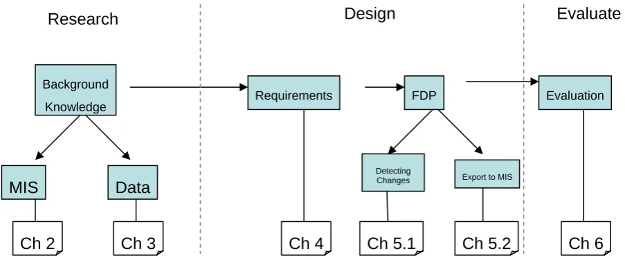
[image:10.595.70.522.199.387.2]A schematic overview of the research can be found in Figure 1 - Schematic overview of the research process.
Figure 1 - Schematic overview of the research process
1.6. Related research
This research covers two main research topics: functional design patterns and management information systems. Technical design patterns and management information systems have been researched often, but research in the topic of functional design patterns is quite new. There is no research which combines both the topics of functional design patterns and exports to management information system. Previous researches on the topic of functional design and functional design patterns primarily focused on formalising the creation of the functional design and the structure of a functional design pattern.
MIS Data
Requirements FDP Evaluation
Background Knowledge
Detecting
Changes Export to MIS
Ch 2 Ch 3 Ch 4 Ch 5.1 Ch 5.2 Ch 6
Evaluate Design
2. Management Information Systems
Management Information Systems are large repositories of data collected by a company. These systems collect data from other systems and enable the management of a company to run complex queries on the data. Sales records can show hidden trends or reveal interesting products which are often bought together. This chapter will cover the basics of Management Information Systems that are important for importing data from another system. This
knowledge is required background information to answer research question 1. First, the use of a Management Information System is given using a simple example, after which the structure of such a system will be explained. The structure of a Management Information System enables managers to do complex queries, which results in aggregated data. The results of these queries are covered.
2.1. Context
A well-known example which is often used is the "beer-and-diapers" myth (which is often discussed [Pow02]). This legend tells a story about a supermarket chain which pioneered in data mining, discovering an interesting relationship between two products which were often sold together. The story goes that data mining revealed the fact that diapers were often sold together with beer, especially on certain times. The myth tells us that fathers buy the diapers on these times, when they return after work and buy themselves a six-pack of beer as a reward. The supermarket decided to rearrange the layout of the store to increase the sales of both items and realized it should sell the beer and diapers on full price on these times. Whether this story is true or not, it does show a simple application of a Management Information System and its use.
In literature, and in practice even more, the terms Management Information System, Decision Support System and Data Warehouse are all used to describe the kind of systems: storing and analysing large amounts of gathered data. There is a difference between these 3 terms, mainly in purpose.
Data mining is the name for analyzing loads of data to extract potential interesting facts. Data mining is performed on data in data warehouses. Data warehouses contain a logical collection of information, gathered from many different sources and support the lower level decision-making process. The data warehouse is a physical repository where relational data is organised to provide clean, enterprise-wide data in a standard format. Decision support systems and Management Information Systems are built upon one or more data warehouses.
[Inm96]
Decision making in large companies is supported by Decision Support Systems. These systems keep track of a list of recent happenings, which the operational manager can analyse with a few simple tools. Decision Support Systems are mostly built based on a data
warehouse, where the data is actually stored. However, it is only limited able to aggregate data and generate custom reports like data cubes. The user is aided in making a decision with plain data.
Management Information Systems are targeted at a higher level of management and are not for daily operation decisions. These Management Information Systems are using the same data input, but they are able to combine multiple sources of data and generate large
Table 1- DSS versus MIS: Comparison of properties
DSS MIS
Goal Analyse current activities Processes optimization and forecast internal data
Decision level Operational Tactical
Output Records Cubes / totals
Detail High, individual items Aggregated only
Age of data Current Historical, current and prediction
2.1. Structure of a Management Information System
To be able to send data to a Management Information System and use the data in queries, we should be aware of the inner structure of a Management Information System and the way it handles data.
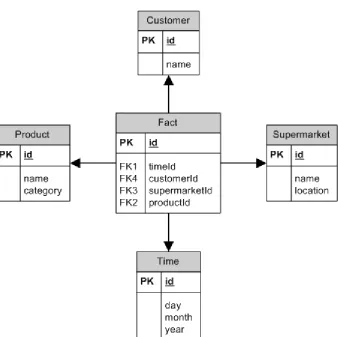
Figure 2 - Supermarket sales data warehouse - example star schema
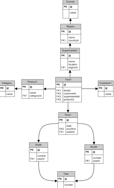
One of the most important features of a data warehouse is drilling up and rolling down (see section 2.3). To accomplish such behaviour in a database, the data needs to be added into the database. The leafs of the star schema are expanded into multiple levels of information. The location of a supermarket can be split up into regions, countries, cities and so on. Time of sale can be split up into weeks, months and years. When the data is split in month, year and week reports, multiple paths are formed starting from the fact table. The splitting of the data results in a branched schema, built around the central fact table. A graphical representation of such a schema looks like a snow flake, hence the name given. Our example supermarket could have the imaginary snow flake schema in Figure 3. A snow flake schema is generally more
2.2. Queries on a Management Information System
Data in Management Information Systems is stored internally in tables structured like the star and snowflake in section 2.1. These tables in a Management Information System are
comparable to ordinary tables in relation databases. Queries on the Management Information System will often contain multiple dimensions, for which a standard two dimensional report or table will not suffice. These results will be presented in a data cube, which can display the data in a three dimensional image and show three dimensions in the data in one image.
Data cubes are defined as an operator on the data in the data warehouse [GCB+97]. It
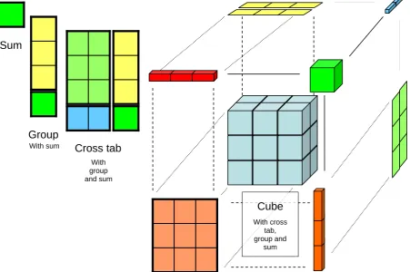
combines the power of grouping, cross-tabbing and totalling into a single operation and result. We omit the technical details which can be found in the paper of Gray et al, and focus on the result of cube queries. These results can be visualised like their name implies, in cubes. An example of such a cube is given in Figure 4, where the sale of cars is depicted. There are two brands of cars available, Chevrolet and Ford; both cars are available in three base colours.
Top left is the result of the query which sums all the sales made by the company. This is a simple aggregation which can be done by the Management Information System. The result can be refined using a query which gives the sales for the single colours of cars and the total sales. The second table illustrates this result.
Even more detailed reports can be created by adding another dimension, the brand of the cars sold. The third result of a report has both dimensions and aggregates. To add another
dimension, the year when the cars are sold, another dimension in the image is required as well. The data cube in the bottom right corner is a result of a cube query on the cars and all three dimensions. The user or manager can view all individual results and browse the sums of all combinations of the dimensions.
Cube
With cross tab, group and
sum
Sum
Group
Cross tab
With sum
[image:15.595.76.528.426.726.2]With group and sum
2.3. Operations on Management Information Systems’ results
One of the most important properties of a Management Information System, as mentioned in section 2.1 is the ability to ‘zoom’ the results. It is possible to add a dimension of analysis –
drilling down- and disaggregate the data that is found. The other way around, thus removing a dimension of analysis and aggregating data, is called rolling up.
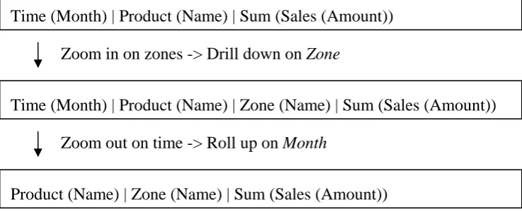
Time (Month) | Product (Name) | Sum (Sales (Amount))
Time (Month) | Product (Name) | Zone (Name) | Sum (Sales (Amount)) Zoom in on zones -> Drill down on Zone
Zoom out on time -> Roll up on Month
[image:16.595.80.449.177.327.2]Product (Name) | Zone (Name) | Sum (Sales (Amount))
Figure 5 - Management Information System - Rolling up and drilling down
As visualised in Figure 5, rolling up and drilling down are complementary functions. Drilling down into the result will show a more detailed report, where as rolling up will show a broader view of the results. The example in the figure shows a change in focus by drilling down on
Zone, resulting in a report similar to the first one, but split by the Zone in which the products are sold. By rolling up on Month, the data is aggregated again and totals for all months are shown.
In Figure 4 these operations are also visible, as the zoom on the data increases from top left to bottom right. The transition from Aggregation to the Data Cube can be seen as a drilling down operation.
2.4. Using a Management Information System
As said before, the Management Information System is used to answer the information need of managers on tactical level. However, this is a relatively vague description of the queries that can be expected to be run on a Management Information System.
Queries on a Management Information system can be placed in four main categories:
Analysis of current situation
Analysis of past trends
Prediction of future, when nothing changes
Prediction of future, when something changes
2.4.1. Analysis of current situation
Management Information Systems can be used as a Decision Support System by operational managers to analyse records about the current situation. The managers can investigate current sales records of the stores and control the daily operation. In an insurance company, these types of reports can show the number of different policies and coverages, providing basic information to the management.
2.4.2. Analysis of past trends
Above the Decision Support queries in section 2.4.1, more complicated queries can be run on the Management Information System, which can analyse the data over time. What trends are visible in the sales of certain items, what regions are upcoming markets and which are lacking in growth?
Even more detailed queries, which evaluate a previous decision, can be run on a Management Information System. Imagine a certain management decision to drop a certain product was made somewhere in the past. The Management Information System can show the results of that decision in all regions and the effect on other products. Furthermore, the information that was available on the date of decision can be compared to the information that is available later, to determine whether the decision was a good decision. Bad decisions can be traced and the cause or lack in information can be determined and future decisions can use this
knowledge.
Effects of a promotion campaign can also be evaluated with a Management Information System. The amount of products sold after the date the promotion has started, optionally aggregated, can be viewed and analysed. Did the customers buy more of the promoted product, did other products benefit as well or did they decrease?
2.4.3. Prediction of future, when nothing changes
By interpolating to the analysis of trends in the past, future situations can be predicted. Linear interpolation for example can be used to predict future results. Cyclic behaviour, like a
season-bound amount of sales for fruit, can be filtered and extended into future predictions.
Using known behaviour of a set of policies in an insurance company, a prediction can be made about a set of current policies. Will these policies still exist in ten years, what properties will change or what other products will these customers buy?
2.4.4. Prediction of future, when something changes
Similar to the prediction of the future of items in the database when nothing changes in the environment, a prediction can be made for cases with changes. What will happen to a set of data when management decides to launch a certain promotion campaign or change the price plan? For example in the insurance company, what will happen to a large set of policies when a new policy type is introduced? Will this attract new customers or will existing customers switch to the new policy?
2.5. Methods to fill a Management Information System
2.5.1. Continuous stream
When connecting a Management Information System to a production system, it is possible to forward all changes on the production environment immediately to the Management
Information System. This means the export function should be notified for every update in the system and a message has to be sent to the Management Information System.
This solution will lead to very up-to-date information in the Management Information System, but it will result in a high load on the Management Information System, which has to
recalculate all aggregate data and data cubes after the insertion. In practice, this option will never be used for these performance issues. It is included in this overview to be complete.
2.5.2. Batch
A batch export collects the appropriate additions, changes and deletions in a batch queue, which can be sent to the Management Information System using either a manual export or a scheduled export, or a combination of both. The queue can be implemented in many different ways for example a database table, a queue dump file or a XML file, or can even be created upon export itself.
Manual export
A manual batch export function will gather all additions, changes and deletions, or all entities that need to be exported in the batch queue. A user can start the export process at any time, for example by pressing a button or executing a certain command. The export process will empty the export queue and send the appropriate data to the Management Information System, which imports all data. After the data is sent to the Management Information System, the queue can be emptied.
A result of the manual start of the process is a random rate of export. As the user can press the button any time or forget to export the data, there is no certainty about the export interval. This might result in out-of-date information in the Management Information System or a loss of granularity for data with history types that have a granularity that is equal to the export rate (see section 3.4)
Scheduled batch
A scheduled batch will result in a similar export as a manual batch. However, the execution of the export is triggered by a scheduled task and the export will occur at a regular time interval. The granularity of the data in the Management Information System is strictly regulated by the rate of execution of the scheduled task. A scheduled export generally takes place at a moment of low load on the production system, for example every night.
When an error occurs and the scheduled export is not executed, the export queue will not be emptied. The data in will remain in the queue and will be exported later. No data is lost, but due to the nature of certain types of history (see section 3.4), the granularity of the data in the Management Information System might decrease.
2.6. Exporting to a Management Information System
The Management Information System stores data in data format of its own. Conversion to that data format is performed when the data is loaded in the Management Information System.
To create highly detailed information, it is important all information is sent to the Management Information System, before it is aggregated. Aggregation will be done in the Management Information System, if required.
3. Data in Production Systems
Computer systems, whether they are small or large, are built on base of data. Administrative applications depend on this internal data, as storing and handling the data is its main purpose. The data in the system does not all have the same value and functionality. In this chapter, a number of properties of data in production systems is used to select a method to export it. The list of properties has been created from information gathered in interview sessions with software engineers. The knowledge about the data is important for the creation of the functional design pattern in research question 4.
3.1. Context
This section will define a number of data types given two example cases. These data types prove to be useful in the selection process of the export. The first example is based on the policy administration of an insurance company. The second example case will discuss the data types occurring in the administration of a book seller. These examples are created similar to systems that are already in use.
3.1.1. Insurance Company
This example presents the administration of policies by an insurance company. The main purpose of the administration is to keep track of the policies that are sold, which makes this the first data type. The insurance company sells the policies using third parties, a network of intermediaries. The system should keep track of the intermediary that has sold the policy. This data will be used to determine the provision earned by the intermediary. The amount of
provision paid is dependent on agreements between the insurance company and the intermediary. These agreements can be made on different levels and are stored in the administration system.
Policies
Customer Intermediary
Production
Insurance company Policy
Employee
Claim
The intermediaries can log in to the system using their user account. Employees of the insurance company can also use a user account to check the policy in case of a claim. The user accounts are part of the data structure of the system.
3.1.2. Book Seller
Imagine a book seller selling books to students on different schools. The book seller offers bundles of books, composed by the school of the student, and single books which can be ordered separately. A student of a school can place an order for the bundle of his class and optional other books on-line, after which the book seller delivers the order to the school.
The system should keep track of the students that place an order and the list of schools that are affiliated to the book seller. The system has a list of items that can be bought,
accompanied by a list of properties of these items. In addition to the names of the school, a reference to a table with the city the school is situated is included.
To be able to see what happened in the system, an audit log is maintained to track users.
Book seller Information Systems Distribution $ School Student Order System maintainer $ $ Management
Management Information System
Books
Export changes / logs
MICROSOFT CORPORATION
Reports
3.2. Data types in production systems
As we can see in the previous examples, different kinds of data exist in the database of a production system. The policies of the insurance company differ greatly in functional properties from the postal code references. The distinction between these data types is quite obvious: we can recognise production data and reference data tables. However, the broad classification of production data includes a large amount of data fields and only makes almost no sense. For example, the amounts of data of policies and intermediaries, and students and schools in the example systems differ tremendously. This makes us introduce multiple levels of production data: the main production data and semi-production data. Both share the property of growing with the system site, but the amount of semi-production data is smaller. User data and agreement data can also be classified as semi-production data.
In addition to the production data, some data is used to define the structure of the other elements. The properties of the items sold by the book seller and the contents of a bundle can be dynamically defined using this structural data.
In the previous paragraphs we have identified a number of data types in production systems. An overview:
Production data
Semi-production data
User data
Data about the structure of the data
Logging data
3.3. Properties of data in production systems
The data in the examples in section 3.1.1 and 3.1.2 all have different properties. This section will focus on the data types defined in section 3.2 and highlight some of the main properties of these data types.
3.3.1. Amount of additions
This property describes the amount of inserted entities of this data type. An insertion can be a creation of a new instance of an entity, a new log line or the addition of a record in a reference table. The growth of a table with a lot of additions is bound to the growth of the system.
To determine the amount of additions and changes of a certain data type, a small interview with software designers has been performed. The conclusions are quite straight-forward. The amount of additions in production data itself is high, as this is the most important function of a software system. For semi-production data the amount of additions is considerably lower, but it can still not be neglected. This will lead to the classification ‘Medium’. In practice, semi-production data is separated from the production data by the software designer
depending on the amount of data. The main purpose of logging data is to store actions of the system and users in the log. This leads to a high amount of additions in the log data. User and reference data are static tables which only have a small amount of new entries during the use of the system. One might expect the structural data has a low amount of additions as well, but this is not true. Software engineers have indicated that it is likely that products and data are added multiple times a year.
3.3.2. Amount of changes
Data tends to change over time, and this property of the data indicates the amount of changes in the data. A change is defined as a change of an entity, a change of a property or a change of an attribute. The original entity, property or attribute was already contained in the database.
The amount of changes in existing data is quite low for all classes of data. Only production data will change relatively often, but only in comparison to the other types. When compared to the number of additions in a system, the number of changes is extremely low. However, to be able to compare the number of changes, a scale has to be used. The ‘medium’ tag for production data is used to indicate the absolute low, but relatively high number of changes. All other data has a ‘low’ tag, except the logging, in which an existing record is never changed.
3.3.3. Type of history in production system
Some elements have a complete history of previous versions in the system. The details about history in a production system and how this can be stored are described in section 3.4.3. Does this type of data usually contain a history in the production system?
3.3.4. Type of history in MIS
System is based on the queries that should be answered by the Management Information System. The availability of a history in the Management Information System is based on the design decisions made by the developers of that system. When exporting to a Management Information System, the developer of the export function cannot influence this history. However, the developer should be aware of the type of history used and the possible drawbacks of exporting data with another type of history.
3.3.5. Is meta data
Some data in the production system does relate to the administrated products itself, but the data is describing the production system or describing properties the data itself. The value for ‘is meta data’ is set to true if the data is describing the administration system or the data that is stored.
[image:23.595.83.465.380.666.2]Certain data is meta data when it describes information about other data or about the structure of the data. This means structure describing data and logging are meta data, and user data can be meta data. When user data looks like production data, for instance when the users are customers who can enter orders into the system, the user data is not meta data. However, when the users are not part of the production data, user data is meta data.
Table 2 - Properties of data types
History in production system
Amount of additions Amount of changes History in MIS Is me
ta da
ta
Production data High Medium Yes Yes No
Semi-production data Medium Low No Yes No
Reference data Low Low No No No
Structure describing data Low Low No No Yes
User data Medium Low Yes No Yes
Logging High None No No Yes
specific implementation in a production system can result in a reference table where a lot of rows are added. Exceptions are possible and should be detected by the designer.
3.4. Time dependent data
In production systems, many entities only have a limited time of validity. For instance, a certain book of the book seller in section 3.1.2 can only be ordered in a promotion week. References to the book do have to be stored beyond the promotion period, but new references are not allowed. When exporting data to the Management Information System, problems arise with this time dependent data. The problems will be worked out in section 4.
Time dependency is a well known issue in system engineering. Carlson et al [CEF98] have written a pattern for a solution for historical mapping of data. The authors recognise the temporal properties of data objects and describe a structured solution for this problem. They call this solution an Analysis Pattern, but the information in the pattern itself is similar to what a functional design pattern would contain.
3.4.1. Reading valid data
In production systems, only data that is valid on a certain time should be read. To accomplish this, flag for validity or a set of timestamps of periods in which the data is valid needs to be added to the data. By checking this flag or these timestamps, it can be guaranteed the data is valid at the time of reading.
3.4.2. Referencing valid data
Like reading data, referencing data in a system can also be time dependent. Certain records are only allowed to be referenced when the data is valid or in a certain period of time. To limit the system to only reference valid data, a trick similar to the reading has to be applied to the references: a time stamp for validity should be added. A reference can only be made if the field is allowed to be referenced, but existing references are kept. This way, information about old references is never lost.
3.4.3. History and time dependent data
A history for data object in a database keeps track of previous versions of that entity. Two different types of implementation for history of a data object can be distinguished:
Stacked history
Stacked history stores a stack of versions in the system. When a change is made, a complete new copy of the instance is placed on the stack. Scheduled versions can be placed on the stack as well. Changes that are in a workflow and are still being evaluated are placed on top of the stack,
blocking other changes and versions to be added on top. When the scheduled change is applied, the change will be placed on the stack as a ‘normal’ version. New versions and changes can now be added to the stack. It is not possible to change a version on the stack that already has a new version or change on top.
This method of storing the history enables linking an object to a historical version of another object: all versions are stored as a single instance in the database. Another object
Version 1 Version 2 Version 3 Pending change H is to ry Fu tu re Version 4 now
Change history
In this history implementation, only the changes of the data are stored in the production system. The old value, the new value, optionally the person that changed the data and a time stamp are stored for every change. This means no future changes can be stored in this implementation and all previous versions can be recreated by negating the logged changes. Because changes can only be stored once they are applied to the object, this method of storing a history does
not support scheduled changes or changes in the past. A change can only be applied on the time it is created. This results in an increased level of certainty of the data, as changes that are exported to the Management Information System cannot be changed afterwards.
Base version Change set
1 Change set
2 Change set
3
History
now
Figure 7 - Change history
3.4.4. Second dimension of time dependent data
Data can have a temporal dimension, the so called time-dependency of data. However, this temporal data can change over time as well. In practice, this means that what is known about the history and future is depending on the time the data is viewed at. The version stack, representing the first dimension of time dependency, of an item in the database can be changed at any moment. We will illustrate the second dimension of time dependency using a real life example: the world history. It is easy to see that the future at any time is unknown and events which are still to happen are not known at a certain point in time, but the most interesting part is the history. Knowledge about the history, especially the ancient history, changes also over time. New findings change our perception of the history, and thus the representation of it. As representation of the history we use history books, which describe the known history at a certain point in time. The books that are currently in use display the same history, but the contents will differ.
If we compare the representation of this history in history books, and our history of data in version stacks, it is easy to see the version stacks have a second dimension of time
dependency as well.
Turnover
0 5 10 15 20 25 30
jan feb mar apr may jun jul aug
Month
A
m
ount (x
1
000)
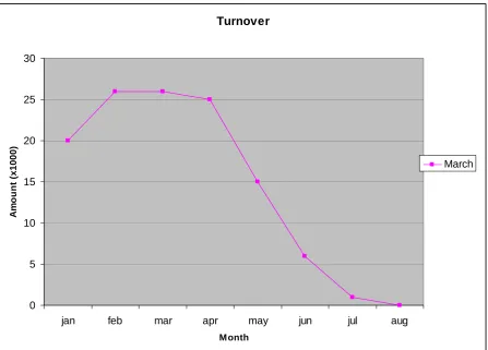
[image:26.595.95.541.111.376.2]February
Figure 9a - Time dependent data - Turnover February
Turnover
0 5 10 15 20 25 30
jan feb mar apr may jun jul aug
M onth
A
m
o
u
n
t (
x100
0)
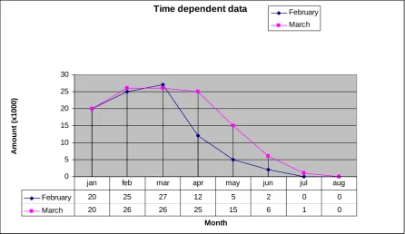
[image:26.595.85.533.425.746.2]The total turnover for the policies in the database is plotted in Figure 10. In this figure, the both previous figures are combined. The lines of the time dependent data differ for both calculations and the report is thus dependent on time as well.
Time dependent data
0 5 10 15 20 25 30 Month A m ou nt ( x 1 0 0 0 ) February March
February 20 25 27 12 5 2 0 0
March 20 26 26 25 15 6 1 0
[image:27.595.74.521.141.399.2]jan feb mar apr may jun jul aug
Figure 10 - Two time dependent data items; the turnover of two monthly totals of time dependent data shows time dependency as well.
Small changes have been made in past month as a result of a retroaction in February. More data has become available for the future month and a scheduled policy for July has even been added.
When exporting data to a Management Information System, this extra level of time dependency is also added to the data. This is caused by the history of the data, which can change over time, similar to the turnover in Figure 10. The time dependent history of a certain object can differ on two different times of inspection. This means the data available is
dependent on the time of access or the time of the snapshot taken.
The data tends to become more certain over time. Data which is in the near past will be more likely to be affected by a retroaction than data that is in the far past. For a Management Information System, this has no direct implication. However, if a lot of retroactions happen, which is the case in the insurance business, a Management Information System should not analyse fresh data.
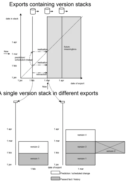
Figure 11 - Two axis of time dependency; Top: different exports, bottom: a version stack in these exports
in the first export and is under the line in the second export is a realisation of the data: the data has become reality. (Of course this can be changed by a retroaction). Retroactions are visible at the top of the figure as a change of an object which was already below the diagonal.
Figure 12 – Two axis of time dependency; actions on the axes: predictions, realisations and retroactions.
The time dependent data can be projected on two axes. In Figure 12, these axes are plotted and show the time throughout both axes. A certain version stack, exported in February already has a predicted value for March. This is visualised on the vertical axis in Figure 12.
Following the horizontal axis from any version in a version stack which is not in the past, depicts the realisation of that version. For a version in the past, a change on the horizontal axis is a retroaction. As there are no exports in the future, all data on the horizontal axis beyond the last export is empty.
represents the date in the version stack, thus the time different versions are valid according to the version stack on the time of export.
Figure 13 - Two axis of time dependency; time in version stack and time of observation of the stack
3.5. Exporting data
As we have seen in this chapter, several properties of data in production systems are important for the export to a Management Information System. These elements have to be included in the functional design pattern. A small summary of these items:
Different data types have to be exported in a different way
Determining the data type of an item in the production system can be done using the list of properties in section 3.2.
4. Requirements
When exporting data from a production environment to a Management Information System, a simple copy-action does not suffice. Due to the nature of the queries that have to be run on the Management Information System and an amount of data in the production environment that is not endless, both ends have a number of requirements on both ends and the data that is
exported. These requirements are used as the base for the definition of the functional design pattern, which is constructed to answer research question 4 and described in the next chapters.
The resolution of detail in the Management Information System is limited by the export rate of the production system, when the data in the production system does not have a history of the object itself. Only the snapshots taken on the export dates are available to the
Management Information System. For data with a history, the granularity depends on the elements that are exported. If the complete stack of history, or all changes since last export, is exported, the history of the object is fully available in the Management Information System. However, if only the current version is exported, the first goes: the available granularity is equal to the export rate.
4.1. Requirements on production system
4.1.1. Detecting changed items
To optimize the size of the export, it is possible to only export the items that have been added, changed or deleted. Items that are completely the same since last export do not have to be exported to the Management Information System, decreasing traffic between the two environments.
To track the changes in the production system, a time stamp of the last change needs be added to the data in the production system. The export function should remember the timestamp of the last export, to compare it with the time stamp of change and determine whether to export the data. The export function can store the timestamp of the last export globally, or for every data object.
The storage of the timestamp in a global method enables the export to multiple Management Information Systems. The time of export for every single Management Information System can be stored. When the export is started, all data that has been changed since last export is selected and these items are exported. To detect which data has been changed, all entities in the database need a timestamp which tracks the time the entity has been changed. Upon export, the value for all entities of this field needs to be compared to the time of the last export. The entities that are changed after this timestamp are exported. This way of detecting the data that has to be exported has an advantage: multiple export timestamps can be stored and can easily be maintained in a single table. However, a number of disadvantages can be found: as the time of last change of all entities has to be compared upon export, the load on the system is considerable high. Also, the object is exported if a property that is not applicable for export to the Management Information System is changed, as all changes, even minor and unimportant ones will trigger the timestamp of last change to be updated.
objects will have a field for every export. This leads to a large number of fields and is hard to maintain.
A complete other strategy to store the changed items in a database, is not including a timestamp of the last export, but including a reference to a record in a special export. This method enables tracking back in which exports a certain item was included. If only the last export of a certain item needs to be reconstructed, the item needs only a reference to the record of the last export. If all exports need to be reconstructed (for security or backup reasons for example), an associative table which links objects and export record is required. When an export is required, all records that links to the current export are selected and exported, while the export record is marked as being exported (with a flag, a time stamp or both) and a new, future export is created in the table. Objects that are created, updated or deleted and need to be exported, will receive a reference to this new record. This method does require a simple selection of references (which may contain an index), an update of the old export record and the creation of a new export record. Because a change of the record is already an update, adding a reference to the future export does not require an extra update, as it can be included.
4.1.2. Handling deletions
Not all Management Information Systems are able to work with invalidated or deleted objects. These objects contain a flag or a date, which invalidates them at a certain point of time. The object itself does still exist in the database and all properties are preserved. If such a system is used, the production system should export a deletion of the data at the given time, after which the Management Information System can use its internal functions to mark the object as deleted.
4.2. Requirements on Management Information System
The requirements on the Management Information System can only be specified in the
functional design of the system itself, not in a pattern. This is because the requirements on the system mainly depend on the wishes of the end users of the Management Information System and not on the data provided. The Management Information System should transform the data in the export received into its internal data structure (section 2.1). The exact format of this data depends on the queries that the management intend to run on the system.
The data in the Management Information System must be optimised to speed up the queries. Because imports on the system can be done while the management is not running queries, for example at night, the data is in a solid state. This means the Management Information System can create parts of the query results in advance, when all data is added. For example,
aggregates and data cubes are best computed directly after the data set has been imported. The data will not change until next export and aggregates do not have to be recomputed.
4.3. Requirements on exported data
When no history is required in the Management Information System, for example for a basic reference table, export is straightforward: Only additions and changes have to be exported and can be added or changed directly in the Management Information System. It is not required to store a change in the Management Information System in either a version stack or a change history.
For data that does not have a history in the production system, but a history in the
Information System, or the complete table has to be exported and changes have to be marked or detected in the Management Information System.
Even when there is a history available in the production system, export to a Management Information System with a history is not trivial and some restrictions on the data exported have to be dealt with.
For exporting history from a production server to a Management Information Server, nine different possible combinations of history can be defined. Because all of these options have a different impact on the export, they will all be explained in a separate section.
4.3.1. No history in production environment
This section will discuss the requirements on the data export when the production system keeps no history of items itself. Because there is no history, there is also no record of changes between different exports. This means the best detail that is possible in the Management Information System is equal to the export rate of the system. Multiple changes that happen between two exports will be exported in the next export as one: the Management Information System does not receive any information about the actual time of both changes. It is not possible to recreate two single changes out of the aggregated change ever again.
Another result of the lack of history in the production system is the inability to do retroactions, which means no data can be changed in the past. Because there is no time dependent date (see section 3.4) it holds that the data that is exported, is valid at that time and will never have another value for that date.
No history in Management Information System
When both the production system and the Management Information System do not keep a history of the data items, all changes are corrections of the data. The production system should export a correction to the Management Information System, which should correct the data in its database as accordingly.
An example of data without history is the name of a bank. If the name of the bank is changed, it is also corrected in the Management Information System. The change on the name has no effect on the owners of the bank accounts and the balance of these bank accounts will not change. Reports on a given date can only be run on the current name of bank, which automatically includes all previous balances. However, if the name has changed in the
Management Information System, it is not possible to generate reports on the old name of the bank, as all references from the bank accounts are pointing to the new name for all places in time.
To improve performance and minimize the traffic between production environment and the Management Information System, it is possible for the production system to send only changed data. This method is similar to the change history method in the next section, however only the change history since the last export is stored. After export, the log of previous changes is deleted. The result of this export is similar to having a complete change history in the production system (section 4.3.2).
Change history in Management Information System
As the changes can only be compared at the times of export, it is not possible to distinguish two single changes between exports. This means it is not possible to reference one of these versions individually. This is illustrated in Figure 14, where object A has a reference to object B. A is originally in state a1 and is changed in version a2. Object B is changed twice, from
state b1 to b2, and from b2 to b3. The data is exported twice, and the reference is kept.
However, the Management Information System is not aware of a reference between a1, a2 and b2. It is aware of the reference between the objects, but it is not able to make a reference to a
certain version.
Production system MIS
Object References Object References
a1 b1 export -> a1 b1
a1 b2 a1 b1
a2 b2 a1 b1
[image:34.595.104.495.187.347.2]a2 b3 export -> a2 b3
Figure 14 - Export of change history - Lost reference
Version stack in Management Information System
For Management Information Systems that keep a complete version stack, the same holds as the previous case in which a change history has to be built. The production system still does not have a history, thus has to export the current data. This is the only data that is available. With this data, the Management Information System has to construct the version stack. It compares the received data with the data on top of the stack and creates a new version if the data is different. Because of multiple changes that occur in the production environment, which are exported at once, the Management Information System cannot reconstruct all versions. This means a reference cannot be made to a specific historic version.
An example of a data item that does not have a history in production, but has a history in a Management Information System, is the address of a bank. For the balance of a certain account it is not important to know where the bank is situated. But if the management wants to evaluate the savings over time on regions, it is important a movement of a bank is stored in different versions to which the bank accounts can reference.
4.3.2. Change history in production environment
Many production environments keep track of the history of a data object with a change history in a log method (see section 3.4.3). With this data, the Management Information System can reconstruct more of the history of a data object and more information is available of what happened between two exports.
No history in Management Information System
The Management Information System has no time dependent data and there is no data in the past to retroact and there is no detail of the changes.
Change history in Management Information System
When both the production system and the Management Information System keep a change history, the only action for the production system is to export the complete change history to the Management Information System. The change history is analyzed for changes after the last export and copied into the Management Information System.
After the export has completed, both systems share the same change history of an object and full detail is preserved.
Version stack in Management Information System
A change history in the production system can be imported into a version stack by exporting the current version in the change history. The Management Information System can add the new version into the version stack. Because not all individual changes are exported this way, the detail is equal to the export rate.
If full detail is important, it is possible to export all individual changes to the Management Information System. All versions on the version stack can be rebuilt and full detail is preserved. However, this requires an increased amount of resources while the benefit is minimal.
4.3.3. Version stack in production environment
Many production systems keep a version stack for important data objects. This is required to be able to reference only a certain version of the object.
For example, an insurance policy has different versions, with different coverages for every year. When the owner files a claim for the insurance policy, the claim has to be linked to the policy version that is valid when the claim is filed. This makes is possible to check the coverages that are valid on that point in time and pay the amount due.
No history in Management Information System
When the Management Information System does not keep a history of the item, it is sufficient to export the current version on the stack. The Management Information System receives this version and corrects differences it detects.
Because the Management Information System does not store any temporal data, there is no history at all. Retroactions cannot be performed as corrections are done at export only.
Change history in Management Information System
Version stack in Management Information System
If both the production system and the Management Information System have a version stack to store the history, the production system can send only the new versions on the stack to the Management Information System. The complete stack can be reconstructed in the
Management Information System and references to a specific version are not lost.
4.4. Requirements on the export
Important for the exports to the Management Information System is the history that is
available in the data items. The export does add an extra dimension of time dependency to the data, but it influences the data available in the first dimension of time dependency as well. The choice how to store the history of an item in the production environment can be completely undone by the export.
Table 1 - Overview of history in both production system and MIS and the method to handle the data
History in production History in MIS Action in production Action in M
IS
Level of Detail. Retroactions Referencing old data
No history Export item Correct None No No
Change history Export item Compare versions Store differences Export rate No No No history
Version stack Export item Compare versions Store new versions Export rate No No
No history Export current data Correct None No No
Change history Export all changes Replay changes
Full No No Change
history
Version stack Export current data Compare versions Create appropriate version Export rate / Full No Yes
No history Export current version Correct None No No
Change history Export complete stack Find new versions
Create history for these
Full No No Version stack
Version stack Export complete stack Find new versions
Store new versions
Full Yes Yes