Effects of Doping Elements in
¢
-FeSi
2Prepared Utilizing Cast Iron Scrap Chips
Assayidatul Laila
1,2, Makoto Nanko
3,+and Masatoshi Takeda
31Graduate School of Engineering, Nagaoka University of Technology, Nagaoka 940-2188, Japan
2Department of Manufacturing and Materials Engineering, Kuliyyah of Engineering, International Islamic University,
Kuala Lumpur, 50728, Malaysia
3Department of Mechanical Engineering, Nagaoka University of Technology, Nagaoka 940-2188, Japan
In this work, the thermoelectric properties of p- and n-type¢-FeSi2, prepared utilizing cast iron scrap chips, have been characterized by
measuring the Seebeck coefficient, electrical conductivity and thermal conductivity at temperatures ranging from room temperatures to 800°C. In a previous study, the upgrade recycling of cast iron scrap chips into¢-FeSi2thermoelectric materials was proposed as an eco-friendly and
cost-effective production process. By doping with different substitution concentrations of Co, Mn and Al, the conduction type and properties of¢ -FeSi2can be modified and improved using cast iron scrap chips as a starting material. The effects of the doping elements are discussed for
preparing¢-FeSi2utilizing cast iron scrap chips. Cast iron scrap chips could be preferable as a starting material to replace pure Fe for n- and
p-type¢-FeSi2thermoelectric materials. An optimum composition for n-type¢-FeSi20.94C.I.-0.06Co-1.86Si shows that the largestZTvalue of
0.22 occurs at 700°C, whereas for p-type¢-FeSi20.92C.I.-0.08Mn-1.86Si, the largestZTvalue of 0.17 occurs at 800°C.
[doi:10.2320/matertrans.M2015357]
(Received September 17, 2015; Accepted December 4, 2015; Published January 29, 2016)
Keywords: materials recycling, cast iron scrap chips, thermoelectric performance,¢-FeSi2
1. Introduction
Iron-based alloys often contain more than 2 mass%carbon, 13 mass% silicon and other elements. During the course of solidification and crystallization, graphite precipitates from the melt, which is known as“cast iron”.1)Ferritic alloys are used in machinery, oil and gas equipment for water piping, packer parts, boilers, valve bodies and valve parts. During mechanical processing, cast iron scrap chips are generated. The recycling of cast iron scrap chips is an interesting subject to explore because these chips can be used as a starting material when preparing an iron based material.
Thermoelectric materials have recently attracted renewed interest for potential applications in waste heat recovery systems. To effectively utilize the low temperatures, small scale and widely scattered waste heat, thermoelectric generation provides a solution. This methodology has a conversion efficiency that is independent of the energy scale and is capable of converting thermal energy to electricity. Thermoelectric material properties are typically evaluated using a dimensionlessfigure of merit,ZT, which is expressed as:
ZT ¼¡2·=kðTÞ ð1Þ
where ¡ is the Seebeck coefficient, · is the electrical conductivity, andkis the thermal conductivity.2,3)It is evident that a large Seebeck coefficient, ¡, a high electrical conductivity, ·, and a low thermal conductivity, k, are required to obtain a high dimensionless thermoelectricfigure of merit,ZT, and it is essential for thermoelectric materials to have high values ofZT.
Semiconducting ¢-FeSi2 is considered an attractive thermoelectric material because of its high Seebeck coef-ficient and because it is eco-friendly (the material is composed of two naturally abundant non toxic elements, iron and silicon4)). In addition, ¢-FeSi
2 has an excellent
oxidation resistance at high temperatures such as 800°C.5,6) Sintered ¢-FeSi2 has a high mechanical strength, heat resistance and is chemically stable at high temperatures.7) Therefore, this material has proven to be very useful in thermoelectric generators operating in high temperature conditions without any protection.
Because cast iron consists mainly of iron with carbon and silicon, scrap chips of cast iron are expected to be a good starting material for preparing ¢-FeSi2. We have already proposed the upgrade recycling of cast iron scrap chips to produce ¢-FeSi2 thermoelectric material.8) It is well known that extrinsic thermoelectric ¢-FeSi2 can be prepared by doping Mn or Al to produce p-type material and Co to produce n-type material. However, there are some limitations on the dopant effects in¢-FeSi2 prepared utilizing cast iron scrap chips. Thus, in the present study, the thermoelectric performance and the physical characterizations of ¢-FeSi2 synthesized from cast iron scrap chips using various doping elements (Co, Al and Mn) were evaluated. The purpose of this report is to reveal that the cast iron scrap chips are effective as a starting material for fabricating ¢-FeSi2 and determining if the optimum thermoelectric performance is comparable to what has been previously reported.
2. Experimental
The starting materials for the p-type and n-type ¢-FeSi2 were prepared using the solid-state reaction technique with cast iron scrap chips (the prefix “C.I.” stands for“cast iron scrap chips”and the prefix “P”stands for “pure Fe”, which denotes the alloys formed from pure Fe), along with silicon grains (purity: 99.99%) and Co powder (purity: 99%) for n-type material and Al powder (purity: 99%) and Mn powder (purity: 99%) for p-type material. The chemical composition of the n-type material was cast iron: Co: Si=(1-Co): (0.02<Co<0.08): 1.86 for n-type. For the p-type material, the chemical composition was cast iron: Al: Si=1: (0.09< Al<0.12): (1.86-Al) and cast iron: Mn: Si=(1-Mn): +Corresponding author, E-mail: nanko@mech.nagaokaut.ac.jp
(0.06<Mn<0.1): 1.86. For the Co-doped and Mn-doped ¢-FeSi2 prepared from C.I. scrap chips and pure Fe, the Co and Mn dopants are substituted in the Fe sites. For the Al-dopant, ¢-FeSi2 is prepared from C.I. scrap chips and Al is the p-type dopant, which is substituted for the Si sites.9)
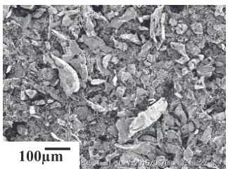
Figure 1 shows an SEM image of the cast iron scrap chip powder. The concentration of impurities in the cast iron scrap chips was analyzed using glow discharge mass spectrometry (GDMS). The results of the impurities are listed in Table 1. For GDMS synthesis, the evaluation of the cast iron scrap chip powders was performed by consolidation using a pulsed electric current sintering (PECS) technique.
The powder mixture was prepared using rotary dry ball milling for 1 d. The powder mixture was placed directly in a die and consolidated using the PECS technique at 950°C for 10 min in a vacuum at a uni-axial pressure of 80 MPa. The sintered specimens were annealed at 900°C for 6 d in a vacuum. The constituent phase and microstructure of the
specimens was observed using a scanning electron micro-scope (SEM) and energy dispersion X-ray spectroscopy (EDXS) for elemental and chemical analyses. The X-ray diffraction (XRD) analysis of the specimens was performed with an X-ray diffractometer.
The thermoelectric properties were determined by measur-ing the Seebeck coefficient, ¡, electrical conductivity, ·, and thermal conductivity, k. The Seebeck coefficient and electrical conductivity were measured using a DC standard four probe method and a steady-state temperature gradient (ZEM-2, Ulvac Co.) from room temperature to 800°C in a stream of He gas. The thermal conductivity was calculated from the measured heat capacity and the thermal diffusivity using the laserflash method with a thermal constant analyzer (LFA 457 Micro Flash) over a temperature range from room temperature to 800°C in a vacuum.
3. Results and Discussion
3.1 Characteristics of p- and n-type ¢-FeSi2 prepared
utilizing cast iron scrap chips
Table 2 shows the density and porosity data of the sintered specimens containing various dopant element (Co, Mn and Al) concentrations for p- and n-type ¢-FeSi2 prepared utilizing cast iron scrap chips. This result indicates that the porosity for all the samples was less than 1%after sintering. Figure 2 shows the XRD patterns of the annealed ¢-FeSi2 containing un-doped, Co-doped, Mn-doped and Al-doped samples prepared from cast iron scrap chips. The prefix
100
μ
m
[image:2.595.88.250.310.430.2]Fig. 1 SEM photo of cast iron scrap chips powder.
Table 1 GDMS composition of elements in cast iron scrap chips.
Element Mass%
Silicon (Si) 2.2
Carbon (C) 2.0
Oxygen (O) 0.5
Manganese (Mn) 0.3
Minor elements: Mg, S, P <0.1
Iron (Fe) Balance
Table 2 Porosity data for the sintered¢-FeSi2samples.
Sample Name
(Numerical Chemical Composition)
Archimedes Measurement
Density Open porosity
0.98C.I.-0.02Co-1.86Si (C.I.-Co0.02) 4.3 g/cm3, 0.3%
0.94C.I.-0.06Co-1.86Si (C.I.-Co0.0.6) 4.3 g/cm3, 0.3%
0.92C.I.-0.08Co-1.86Si (C.I.-Co0.08) 4.3 g/cm3, 0.3% C.I.-0.09Al-1.77Si (C.I.-Al0.09) 4.5 g/cm3, 0.5%
C.I.-0.12Al-1.74Si (C.I.-Al0.12) 4.5 g/cm3, 0.5%
0.94C.I.-0.06Mn-1.86Si (C.I.-Mn0.06) 4.4 g/cm3, 0.5%
0.92C.I.-0.08Mn-1.86Si (C.I.-Mn0.08) 4.4 g/cm3, 0.5%
0.90C.I.-0.1Mn-1.86Si (C.I.-Mn0.1) 4.4 g/cm3, 0.5%
β-FeSi2 ε-FeSi β-FeSi2 ε-FeSi
n-type p-type
20 30 40 50 60 70 80
Diffraction Angle, 2θ/ degree
Intensity,
I
/ a.
u
C.I.-0.09Al-1.77Si 0.94C.I.-0.06Mn-1.86Si
0.9C.I.-0.1Mn-1.86Si 0.92C.I.-0.08Mn-1.86Si
C.I.-0.12Al-1.74Si
20 30 40 50 60 70 80
Diffraction Angle, 2θ/ degree
In
te
n
sity
,
I
/ a.
u
0.94C.I.-0.06Co-1.86Si 0.98C.I.-0.02Co-1.86Si
0.92C.I.-0.08Co-1.86Si
[image:2.595.44.550.462.774.2]“C.I.”stands for“cast iron scrap chips”, which denotes those alloys as being formed from cast iron scrap chips. The dominant peak in all of these samples was ¢-FeSi2. All the samples are composed mainly of the ¢-FeSi2 phase, which means the phase transformation from¡-Fe2Si5and¾-FeSi to ¢-FeSi2is nearly completed after annealing at 900°C for 6 d. The samples consisted of small amounts of the¾-FeSi phase. It was also confirmed that the isothermal annealing near the high temperature transformation temperature led to the distinct formation of¾-FeSi.10)
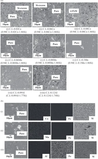
Figure 3(a) shows SEM images of the microstructures for annealed un-doped, Co-doped, Mn-doped and Al-doped ¢ -FeSi2prepared from cast iron scrap chips. The SEM image of the annealed ¢-FeSi2 prepared from cast iron scrap chips showed excess Si particles (shown as black dots) with small pores (shown as white dots). Several black Si particles were detected in the¢-phase matrix. Very few pores were detected in the un-doped, Co-doped, Mn-doped and Al-doped samples. The pore size that could be observed from the SEM images was estimated to be less than approximately 10 µm. The open porosity, as provided in Table 2 observed in all samples was less than 1%after sintering, and we consider these to be dense samples. Figure 3(b) shows the SEM images and the corresponding EDX elemental mapping results for (i) 0.94C.I.-0.06Co-1.86Si (C.I.-Co0.0.6), (ii) 0.92C.I.-0.08Mn-1.86Si (C.I.-Mn0.08) and (iii) C.I.-0.09Al-1.77Si (C.I.-Al0.09) in the annealed ¢-FeSi2 prepared from cast iron scrap chips. It is clear that the distribution of the Co, Mn and Al dopant concentrations in these specimens, as well as for the remaining annealed¢-FeSi2prepared from cast iron scrap chips were uniformly dispersed throughout the¢phase.
3.2 Thermoelectric performances of p- and n-type ¢-FeSi2prepared utilizing cast iron scrap chips
The temperature dependence of the Seebeck coefficient,¡, for the annealed p- and n-type ¢-FeSi2specimens evaluated from room temperature to 800°C is shown in Fig. 4. In the present work,11) we see different signs for the Seebeck coefficients exhibited for the Al-, Mn- and Co-doped¢-FeSi2 prepared from cast iron scrap chips. The positive values associated with the Mn-doped (0.06<Mn<0.1) and Al-doped (0.09<Al<0.12) samples correspond to p-type behavior, indicating that the electrical conductivity is dominated by hole conduction. However, n-type behavior is attributed to the Co-doped (0.02<Co<0.08) samples as a result of their negative Seebeck coefficient values, which is indicative of electron conduction. The absolute value of the Seebeck coefficient increases with the measurement temper-ature to a peak before beginning to decrease with further increases to the temperature. The Seebeck coefficients for the 0.92C.I.-0.08Mn-1.86Si (C.I.-Mn0.08) and 0.94C.I.-0.06Co-1.86Si (C.I.-Co0.0.6) specimens prepared from cast iron scrap chips were obtained to be between 90% and almost 100%, respectively, of the performance observed for the other specimens and from other reported studies.1316)We see that as the Al dopant (0.09<Al<0.12) was replaced by the Mn dopant (0.06<Mn<0.1), the Seebeck coefficients was found to decrease. The decrease in the Seebeck coefficient could be caused by an increase in the carrier concentration. In the present study, it was revealed that the Al dopant
(0.09<Al<0.12) is more sensitive to the cast iron scrap chips due to the Al dopant (0.09<Al<0.12) being easily oxidized during processing because the cast iron contains many impurities. This is most likely a result of oxygen impurities in the cast iron scrap. The Al-doped sample is partially oxidized during machining and exhibited a low performance compared to the Mn-doped (0.06<Mn<0.1) ¢-FeSi2. Thus, the results of this study indicated that¢-FeSi2 prepared utilizing cast iron scrap was successfully optimized and is comparable to what has been previously reported.
Figure 5 shows the temperature dependence of the electrical conductivity for the annealed ¢-FeSi2 specimens between room temperature to 800°C. The electrical con-ductivity of the C.I.-0.09Al-1.77Si (C.I.-Al0.09) specimen decreased with increasing temperatures until reaching 400°C. As this point, further temperature increases resulted in increases to the electrical conductivity. The temperature dependence of the electrical conductivity below 400°C could be attributed to the carrier mobility, which decreased with increasing temperature. This is a result of the acceptor being exhausted and carrier movements occurring via lattice vibration.9) The intrinsic conduction dominated when the temperature is above 400°C, which leads to the increase in the electrical conductivity as the temperature increased. The electrical conductivities for the Co-doped (0.02<Co< 0.08) and Mn-doped (0.06<Mn<0.1) ¢-FeSi2 prepared using cast iron scrap chips, along with other examples reported in the literature,9,1216)are nearly constant over the temperature range from room temperature to 800°C. This behavior is typical for the extrinsic conductivity range. Thus, we confirm that Mn-doped (0.06<Mn<0.1) and Co-doped (0.02<Co<0.08) ¢-FeSi2 prepared using cast iron scrap chips exhibit positive impacts on the electrical conductivity compared to other results reported on in the literature.13,14) Conversely, for p-type¢-FeSi2prepared using cast iron scrap chips, the C.I.-0.09Al-1.77Si (C.I.-Al0.09) exhibited a lower electrical conductivity compared to 0.94C.I.-0.06Mn-1.86Si (C.I.-Mn0.06) and 0.92C.I.-0.08Mn-1.86Si (C.I.-Mn0.08) at temperatures greater than 200°C. Thisfinding indicated that the C.I.-0.09Al-1.77Si (C.I.-Al0.09) is more sensitive to the presence of the cast iron scrap chips, and results in a low concentration upon synthesis. As the Al dopant was replaced by the Mn dopant, the electrical conductivity was enhanced and improved. Therefore, by doping with different substitu-tion concentrasubstitu-tions of Co (0.02<Co<0.08), Mn (0.06< Mn<0.1) and Al (0.09<Co<0.12), the conduction type and properties of the¢-FeSi2can be modified and improved, even when using cast iron scrap chips as a starting material.
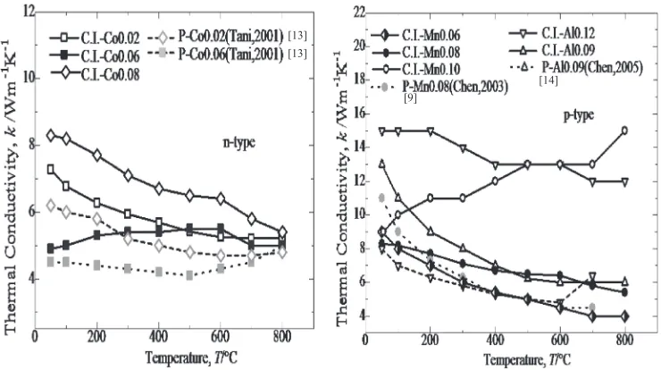
The thermal conductivity,kof the annealed p- and n-type ¢-FeSi2 specimens evaluated from room temperature to 800°C is shown in Fig. 6. For all the specimens, the thermal conductivity,kdecreased rapidly as the temperature increas-ed. Similar trends for the thermal conductivity as a function of measurement temperature was reported by Ito et al.17)
the Co-doped (0.02<Co<0.08) specimens’ thermal con-ductivity was much lower than the p-type doped 0.92C.I.-0.08Mn-1.86Si (C.I.-Mn0.08) and C.I.-0.09Al-1.77Si
(C.I-Al0.09) specimens, respectively. This result could be due to the effect of the Si-rich concentration in the n-type Co-doped (0.02<Co<0.08) ¢-FeSi2 prepared using cast iron scrap (i) C.I.-0.02Co
(0.98C.I.-0.02Co-1.86Si)
(ii) C.I.-0.06Co (0.94C.I.-0.06Co-1.86Si)
(iii) C.I.-0.08Co (0.94C.I.-0.08Co-1.86Si)
Si-excess Si-excess
εε-FeSi
Pore
Pore
10μm 10μm 10μm
10μm
(v) C.I.-0.08Mn (0.94C.I.-0.08Mn-1.86Si) (iv) C.I.-0.06Mn
(0.94C.I.-0.06Mn-1.86Si)
(vi) C.I.-0.1Mn (0.94C.I.-0.1Mn-1.86Si)
Pore Pore Pore
10μm 10μm
10μm
(vii) C.I.-0.09Al (C.I.-0.09Al-1.77Si)
Pore Pore
(viii) C.I.-0.12Al (C.I.-0.12Al-1.74Si)
10μm
(a)
(b)
10μm
Pore
Co Fe Si
10μm
Pore
Mn Fe Si
(i)
(ii)
(iii)
Fe Pore
10μm Al Si
Fig. 3 (a) SEM photos on microstructures of the annealed¢-FeSi2samples at 900°C for 6 d, (b) SEM image and EDX result of (i)
[image:4.595.105.490.74.696.2][9]
[14] [12]
[13]
Fig. 4 Temperature dependence of Seebeck coefficient,¡, for the annealed¢-FeSi2samples at 900°C for 6.
[13] [12]
[9] [14]
Fig. 5 Temperature dependence of electrical conductivity,·, for the annealed¢-FeSi2samples at 900°C for 6 d.
[13]
[9] [13]
[14]
[image:5.595.115.484.70.259.2] [image:5.595.114.484.315.503.2] [image:5.595.114.484.564.771.2]chips. It was reported that this may improve the transport properties of the materials, which is effective at decreasing the thermal conductivity.14)Furthermore, in general, increases in the dopant content tend to enhance the photon scattering due to lattice short range distortions, resulting in a decrease in the thermal conductivity.18)Thus, it was found that by doping with different substitution concentrations of Co (0.02< Co<0.08), Mn (0.06<Mn<0.1) and Al (0.09<Co< 0.12), the conduction type and properties of the¢-FeSi2can be modified and improved, even when using cast iron scrap chips as a starting material.
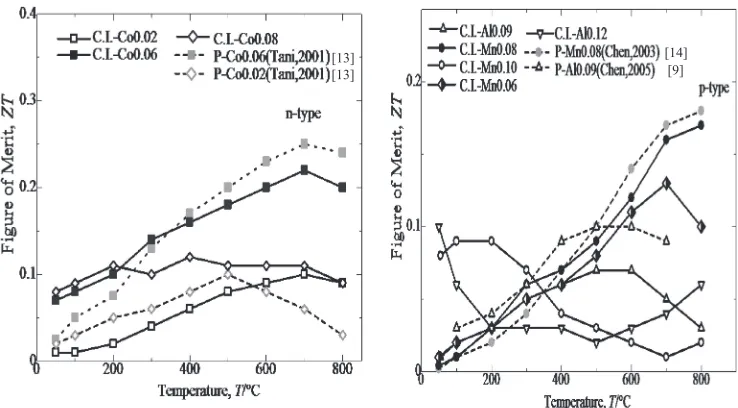
Figure 7 summarizes the function of temperature on the dimensionless figure of merit, ZT, for the various doping elements in the p- and n-type ¢-FeSi2 specimens prepared utilizing cast iron scrap chips. Significant efforts have been undertaken to obtain a high value figure of merit, which represents the efficiency of thermoelectric materials.19,20)The comparison of theZTvalues achieved for the n-type 0.94C.I.-0.06Co-1.86Si (C.I-Co0.06) specimen and the p-type 0.92C.I.-0.08 Mn-1.86Si (C.I.-Mn0.08) specimen with the other various doping elements indicated the highest ZT
values were 0.22 at 700°C and 0.17 at 800°C, respectively. Due to the higher substitutions necessary to achieve the concentration effect, the highest ZT value was obtained from the n-type 0.94C.I.-0.06Co-1.86Si (C.I-Co0.06) speci-men.13,14) Additionally, the p-type specimen prepared from p-type 0.92C.I.-0.08Mn-1.86Si (C.I.-Mn0.08) has a betterZT
value due to the compatibility of the cast iron scrap chips, compared to the results in previously published reports.11)By doping with the various elements, the conduction type and properties of the ¢-FeSi2 prepared utilizing cast-iron scrap chips could be modified and improved. The value of ZT
increases with the temperature before reaching a maximum and decreasing. Additionally, theZTvalue increases with the substitution concentration of the doping elements. Therefore, we have demonstrated that the cast iron scrap chips are effective as a starting material for fabricating¢-FeSi2and are capable of producing a material comparable to conventional ¢-FeSi2fabricated from pure Fe.
Figure 8 reveals the results for the dimensionlessfigure of merit, ZT, for the n-type (0.02<Co<0.08) and (0.06< Mn<0.1) specimens, as well as for the p-type (0.09<Al< 0.12) specimen. Based on the results, the optimized Co substitution concentration for the n-type specimen is 0.94C.I.-0.06Co-1.86Si (C.I-Co0.06), which produces
ZT=0.22 at 700°C. For the p-type specimen,ZT=0.17 at 800°C for 0.92C.I.-0.08Mn-1.86Si (C.I.-Mn0.08). Therefore, there are some restrictions for the alloying elements in the ¢-FeSi2fabricated from cast iron scrap chips. For example, the metallic behavior (corresponding to an excessively high electrical conductivity) and a high sensitivity to dopant oxidation in the cast iron scrap chips could lead to decreases in theZT value. To improve the thermoelectric performance of the p-type¢-FeSi2prepared utilizing cast iron scarp chips, Mn (0.06<Mn<0.1) was chosen to replace Al (0.09< Al<0.12) as the dopant element for the p-type ¢-FeSi2 specimen. In the case of the p-type specimen with Al doping (0.09<Al<0.12), it is important to avoid any oxidation during sintering. For Mn doping (0.06<Mn<0.1), the oxidation is not as severe.21) It is difficult to control Al [13]
[13]
[14] [9]
Fig. 7 Variation in dimensionalfigure of merit,ZT, with the measuring temperature of the annealed¢-FeSi2samples at 900°C for 6 d.
[9] [14] [13]
(800°C) (700°C) (600°C)
Fig. 8 Effects of mol substitution concentration on dimensionlessfigure of merit of the annealed¢-FeSi2samples with cast iron scrap chips at 900°C
[image:6.595.322.530.322.481.2]doping (0.09<Al<0.12) as a result of oxidation, especially when using cast iron scrap chips, as shown in Table 1. An optimum composition for the p-type 0.92C.I.-0.08Mn-1.86Si (C.I.-Mn0.08) and 0.94C.I.-0.06Co-1.86Si (C.I-Co0.06) specimens to provide the largest ZT value for the present system was determined. This effect is caused by the high affinity of Al to oxygen compared to the Mn and Co. The replacement of Al (0.09<Al<0.12) with Mn (0.06< Mn<0.1) as a concentration substitution in p-type¢-FeSi2is quite effective for improving the thermoelectric performance in the¢-FeSi2prepared from cast iron scrap chips. Hence, the conduction type and properties of ¢-FeSi2 can be modified and improved, even when cast iron scrap chips are used as a starting material.
4. Conclusions
The thermoelectric properties of p- and n-type ¢-FeSi2 have been determined by measuring the Seebeck coeeficient, ¡, electrical conductivity,·, and thermal conductivity,k, from room temperature to 800°C. The thermoelectric properties are strongly affected by the Co-doped (0.02<Co<0.08) substitution concentration (for n-type specimens) and Mn-doped (0.06<Mn<0.1) substitution concentration (for p-type specimens). The dimensionless figure of merit for the n-type 0.94C.I.-0.06Co-1.86Si (C.I-Co0.06) and the p-type 0.92C.I.-0.08 Mn-1.86Si (C.I.-Mn0.08) ¢-FeSi2 achieved approximately 90% performance compared with ¢-FeSi2 synthesized from pure Fe and was improved by approx-imately a factor of two compared with the p-type C.I.-0.09Al-1.77Si (C.I.-Al0.09) and n-type 0.948C.I.-0.02Co-1.86Si (C.I.-Co0.02) specimens that have been published previ-ously.11) Thus, the objective of this study to evaluate the effect of doping elements in ¢-FeSi2 prepared utilizing cast iron scrap chips was successfully achieved, and an optimum thermoelectric performance was determined. Compared with the p-type 0.92C.I.-0.08 Mn-1.86Si (C.I.-Mn0.08) specimens prepared from cast iron scrap chips, the n-type 0.94C.I.-0.06Co-1.86Si (C.I-Co0.06) specimen possessed a high electrical conductivity, low thermal conductivity and a high dimensionless figure of merit, ZT=0.22, at a measurement temperature of 700°C due to the high carrier concentration and optimum substitution concentration. The achievedZTis assumed to be comparatively the same for ¢-FeSi2 thermo-electric materials made from pure Fe. Due to the optimum value ofZTobtained in the present study, the use of the cast iron scrap chips as a starting material was found to be promising as an eco-friendly and cost-effective production process for thermoelectric¢-FeSi2. We conclude that the cast
iron scrap chips were successful at fabricating p-type 0.92C.I.-0.08 Mn-1.86Si (C.I.-Mn0.08) and n-type 0.94C.I.-0.06Co-1.86Si (C.I-Co0.06)¢-FeSi2thermoelectric materials and that optimum thermoelectric performances were deter-mined that were comparable with the previously reported results. However, Al doping (0.09<Al<0.12) is not suitable for use with cast iron scrap chips as a starting material for ¢-FeSi2 thermoelectric materials due to the tendency of the Al dopant (0.09<Al<0.12) to be oxidized during machining.
Acknowledgements
The authors would like to express their appreciation to the Ministry of Higher Education of Malaysia for partially supporting this study.
REFERENCES
1) T. Elbel, J. Senberger, A. Zadera and J. Hampl: Arch. Mater. Sci. Eng.
33(2008) 111116.
2) W. S. Cho, S. W. Choi and K. Park:Mater. Sci. Eng. B68(1999) 116 122.
3) M. Ito and Y. Takiguchi:Mater. Trans.46(2005) 14971501. 4) L. Ivanenko, V. Shaposhnikov, A. Filonov, A. Krivosheeva, V.
Borisenko, D. Migas, L. Miglio, G. Behr and J. Schumann: Thin Solid Films461(2004) 141147.
5) S. H. Chang, M. Nanko, K. Matsumaru, K. Ishizaki and M. Takeda:J. Japan Inst. Metals70(2006) 2026.
6) M. Nanko, S. H. Chang, K. Matsumaru, K. Ishizaki and M. Takeda: Mater. Sci. Forum522523(2006) 641648.
7) R. M. Ware and D. J. McNeil:Proc. Inst. Elect. Eng.111(1964) 178 182.
8) A. Laila and M. Nanko:Mater. Sci. Forum804(2014) 36. 9) H. Y. Chen, X. B. Zhao, T. J. Zhu, Y. F. Lu, H. L. Ni, E. Müller and
A. Mrotzek:Intermetallics13(2005) 704709.
10) S. C. Ur: Twenty Second Int. Conf. on Thermoelectric-ICT, (2003) pp. 149152.
11) A. Laila, M. Nanko and M. Takeda:Materials7(2014) 63046316. 12) S. W. Kim, M. K. Cho, Y. Mishima and D. C. Choi:Intermetallics11
(2003) 399405.
13) J. Tani and H. Kido:J. Appl. Phys.40(2001) 32363239.
14) H. Y. Chen, X. B. Zhao, Y. F. Lu, E. Mueller and A. Mrotzek:J. Appl. Phys.94(2003) 662666.
15) J. Tani and H. Kido:J. Appl. Phys.86(1999) 464467. 16) T. Kojima:Phys. Stat. Sol.111(1989) 233242.
17) M. Ito, H. Nagai, T. Tahata, S. Katsuyama and K. Majima:J. Appl. Phys. Stat.92(2002) 3217.
18) O. Yamashita, S. Tomiyoshi and N. Sadatomi:J. Mater. Sci.38(2003) 16231629.
19) H. J. Goldsmid:CRC Handbook of thermoelectricity, ed. by D. M. Rowe, (CRC Press, Boca Raton) (1995) Chapter 3.
20) H. Nagai, T. Katsura, S. Katsuyama, K. Majima and M. Ito:Mater. Trans., JIM39(1998) 11401145.