Woodceramic Heating Elements for Low Temperature Heating
Junichiro Tsuji
1, Riko Ozao
2, Toshihiro Okabe
3, Toshikazu Suda
4and Ryoichi Yamamoto
5 1Polytechnic Center Gunma, Takasaki, Gunma 370-1213, Japan2SONY Institute of Higher Education, Atsugi 243-8501, Japan 3
Industrial Research Institute of Aomori Prefecture, Aomori 030-0113, Japan 4Polytechnic University, Sagamihara 229-1196, Japan
5Center for Collaborative Research, University of Tokyo, Tokyo 153-8904, Japan
Woodceramics are carbon–carbon composites produced by impregnating plant-origin lignocellulosic materials with phenolic resin and by carbonizing the resulting precursor at temperatures higher than 650C. Since the electric resistance of the woodceramics changes as a function of
the carbonizing temperature, heating elements for use in biological incubator systems can be prepared by controlling the electric resistance to obtain optimal Joule heat. Woodceramic heating blocks carbonized at temperatures lower than 800C were found preferable from the viewpoint
of lower water absorptivity. Then, woodceramic test specimens (3105218mm3) were produced from medium density fiberboard (MDF) at carbonizing temperatures of 650, 700, 750, and 800C (which are simply denoted as 650, 700, 750, and 800, respectively). The electric
resistance of the test specimens 650, 700, 750, and 800 at applied voltage of 10 V was 50, 10, 8, and 4, respectively. Thus, single test piece of 650, 3 serially connected 700, 7 serially connected 750, and 10 serially connected 800 were used to obtain the temperature profile. Temperature rise of each test specimen was measured under applied voltages of 10, 20, 30, and 40 V. For 650, fair temperature stability was obtained at 22C
(10 V) and 27–31C (20 V). The advantages of the woodceramic heaters as compared with the conventional ceramic heaters are: (1) quick rise in
temperature; (2) high stability at designated temperature; (3) lower power consumption; and (4) free of air convection (heats the sample directly and homogeneously).
(Received August 17, 2005; Accepted November 8, 2005; Published December 15, 2005)
Keywords: carbon/carbon composite, woodceramics, heater element, water absorption, incubator
1. Introduction
Woodceramics are porous carbon/carbon composites or hybrid materials consisting of cellulose-originated carbon reinforced by glassy carbon generated from resin. They are produced by impregnating carbonaceous materials with thermo-setting resin, such as phenolic resin, and by carbon-izing the resin-impregnated material in a vacuum furnace.1) Woodceramics obtained from wood are generally porous, and have macro-pores with diameter ranging from 1 to 50mm. So far, woodceramics had been produced from wood-based materials, such as hiba (Thujopsis dolabrata var. hondae), cedar (Cryptomeria japonica), pine (Pseudotsuga menziesii), MDF (medium density fiber) boards, waste paper, apple wastes, etc.
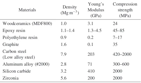
Woodceramics are superior to the original wood in thermal resistance, and because they are porous, their density is normally about 1.0 Mg m3,i.e., about the same as that of epoxy resins or polyethylene resins, and about one third of that of widely used ceramics such as alumina. Physical properties of woodceramics differ depending on the starting material and sintering temperature, however, it is now well established that woodceramics based on medium-density fiberboard of satisfactory strength (3.1 GPa Young’s Mod-ulus, 24 MPa fracture strength) can be obtained by sintering at 800C or higher.2)
Mechanical properties of typical woodceramics obtained from medium density fiberboard (MDF) carbonized at 800C
are compared with other structural materials in Table 1.3)It can be understood that they are lightweight material with considerable strength, and that they are more elastic than ceramics.
In addition to the mechanical properties, woodceramics are interesting because that their resistance can be controlled by
changing the carbonizing temperature.4)Mikiet al.6)reports that the electric resistivity of woodceramics made from MDF mixed with 33 mass% phenolic resin considerably drops with increasing temperature; the resistivity of woodceramics obtained by carbonizing at 650C, which was about
10cm, decreased to ca. 5101cm by carbonizing at
a higher temperature of 800C. Thus, it is expected that a
heater body based on Joule heating can be fabricated by carbonizing wood-based materials at temperatures lower than 800C. However, local heat-up may occur attributed to the
porous nature of the material, or drop in resistance with elevating temperature may lead to the occurrence of runaway effect. Furthermore, it is reported that the resistivity decreases with increasing humidity.5)
[image:1.595.306.549.406.549.2]It is also to be noted that, because woodceramics are porous, their radiant energy (wavelength) distribution is similar to that of black body.3)Thus, woodceramic blocks are expected to provide excellent heating elements capable of
Table 1 Mechanical Properties of woodceramics compared with other structural materials.
Materials Density (Mg m3)
Young’s Modulus (GPa) Compression strength (MPa)
Woodceramics (MDF800) 1.0 3.1 24
Epoxy resin 1.1–1.4 1.3–4.5 45–85
Polyethylene resin 0.9 0.2 7–17
Graphite 1.6 0.1 35
Carbon steel
(Low alloy steel) 7.9 203 420–2000
Aluminum alloy (#2000) 2.8 71 300–600
Silicon carbide 3.2 410 2000
Zirconia 5.6 200 2000
Special Issue on Growth of Ecomaterials as a Key to Eco-Society II
heating at moderate temperatures for use in, e.g., biological incubator systems. Conventional incubator systems utilize warm air heated by ceramic heating elements, and they suffered disadvantages such as (1) lack of uniform heating due to convection, (2) requiring long time for stabilization, (3) low efficiency and high power consumption, and (4) causing inhomogeneous temperature distribution in the heated object.
The present paper reports on the fabrication of heater block which functions effectively when assembled in biological incubator systems. First, carbonizing temperature range was determined by selecting heater blocks having lower water absorption, and then, the optimum heater block configuration was selected by evaluating the temperature controllability or stability.
2. Experimental
2.1 Samples
Woodceramic heating blocks (3105218mm3) for evaluating water absorption characteristics were produced from medium density fiberboard (MDF) at carbonizing temperatures of 650, 800, 1000, and 1200C.
2.2 Experimental setup
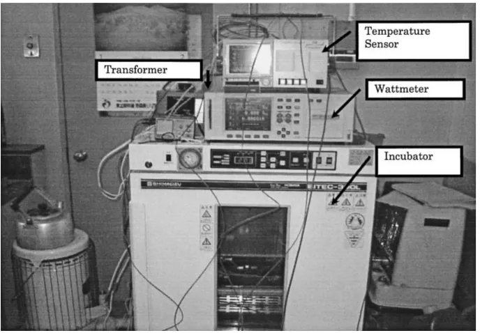
Figure 1 shows the experimental setup for evaluating the woodceramic heating block. It comprises an incubator, a wattmeter, temperature sensor, and a transformer. The temperature inside the incubator was set constant to 20C.
2.3 Optimization of heater block configuration
The electric resistance of the test specimens 650, 700, 750, and 800 at applied voltage of 10 V was 50, 10, 8, and 4, respectively. Similar results were obtained for other applied voltages (See Fig. 2). Thus, in order to set the electric resistance equivalent for all of the heating blocks, the test specimens were serially connected;i.e., 3 blocks of 700 were
serial connected (See Fig. 3), 7 blocks for 750, and 10 blocks for 800.
2.4 Temperature Change with Time
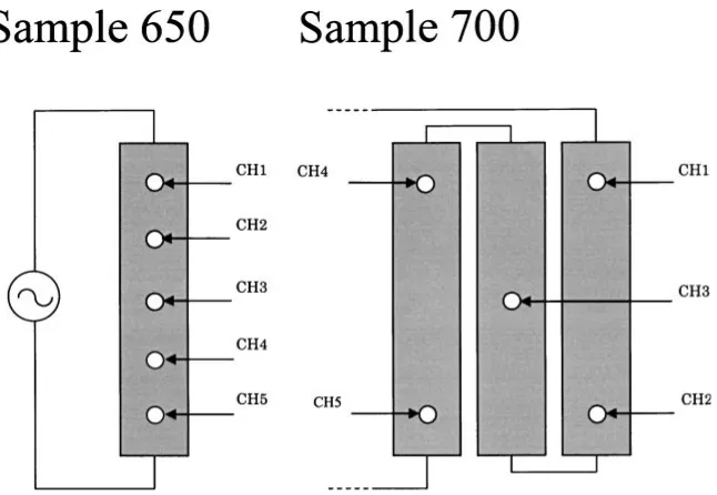
In order to evaluate optimum Joule heat generation, surface temperature of the heating block was measured while changing the applied voltage to 10, 20, 30, and 40 V. To assure uniform heating, the temperature was measured at 5 different points. In Fig. 4 is shown the measuring positions for 650 and 700. Change in temperature was also measured inside the incubator.
3. Results and Discussion
3.1 Sample characterization
Figure 5 shows the volume (cm3), bone-dry weight (g), and the weight (g) after immersing the bone-dried heating blocks in water for 5 h (denoted as ‘‘Wet weight’’, herein-after), of the sample blocks. Figure 6 shows the density of the
Fig. 1 Experimental setup for use in testing woodceramic heating blocks.
[image:2.595.127.471.71.310.2] [image:2.595.318.534.349.502.2]dry sample and the water absorption ratiowof the samples as defined in the following equation (1), after immersing the blocks in water for 5 h.
w¼WwetWdry
Wdry 1
V ð1Þ
where, w represents the water absorption ratio per volume (cm3),Wwet represents the weight (g) after immersing the bone-dried heating blocks in water for 5 h,Wdryrepresents the
Fig. 3 Serial connected three blocks of test specimen 700.
Fig. 4 Temperature measuring points for samples 650 and 700.
Fig. 5 Volume, bone-dry weight, and weight after immersing in water for 5 h of the samples obtained by carbonizing at 650, 800, 1000, and 1200C.
[image:3.595.127.471.71.266.2] [image:3.595.140.463.300.523.2] [image:3.595.309.543.558.676.2] [image:3.595.55.286.559.698.2]bone-dry weight (g), and V represents the volume (cm3) of the bone-dry heating block. The results are given in Fig. 6.
Based on the results above, woodceramics carbonized in the temperature range of 650–800C have been found ideal
for the heating blocks. Thus, woodceramic heating blocks (3105218mm3) for obtaining the temperature profile
were produced from medium density fiberboard (MDF) at carbonizing temperatures of 650, 700, 750 and 800C (which
are denoted hereinafter as sample 650, 700, 750, and 800, respectively).
3.2 Water absorption properties
As described above, since electric resistivity of the heater blocks is influenced by humidity, heater blocks low in water absorption are preferred for use in incubators. As shown in Fig. 5, it can be understood that the volume and the mass slightly decreases with increasing carbonizing temperatures. This result is in good agreement with previous reports;7)it is well established that the mass and the volume considerably decrease when heated from room temperature to 650C, at
which condensation of aromatic polynuclear structure is fully developed from the phenolic resin and the decomposition of the original wood is mostly completed. Kercher and Nagle8) studied the carbonization process of the medium density fiberboard alone and reported that the growth of large turbostratic crystallites ceased at temperatures higher than 600C, and that the graphene sheet grew substantially to
cause volumetric shrinkage. They also suggest the impinge-ment of the conductive graphene sheets causes the nonmetal-metal transition at higher temperatures. In Fig. 6 is shown the density of the woodceramic samples. Although the density for all of the samples is lower than water, samples carbonized at temperatures higher than 800C sunk in the water bath
after 5-h immersion. It can be therefore understood that the sample carbonized at 650C only has water-repelling
property, probably attributed to the remaining water-repel-ling wood-like properties.
It can be clearly understood from the above results that samples carbonized between 650 to 800C are preferred
for heater blocks from the viewpoint of water absorptivitiy, and only samples 650, 700, 750, and 800 are studied here-inafter.
3.3 Change of temperature with time (temperature profile)
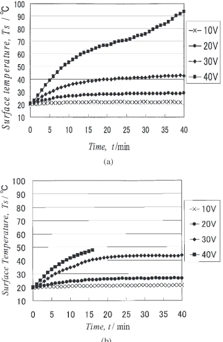
For use as heating elements of incubators, the heating elements must keep the temperature constant at the desired temperature without causing a temperature shoot inside the incubator. Figures 7(a) and (b) show the change of surface temperature for 650 and 700, respectively with passage of time (average of 5 measuring points, CH1–CH5 in Fig. 6). It can be seen that the heater can hold temperature at 22 or 29C
at applied voltage of 10 or 20 V, but at a higher applied voltage of 30 V, the temperature gradually increases with time, and furthermore, it takes longer time to reach a constant temperature. Moreover, temperature overshoot occurs at an applied voltage of 40 V. Higher Joule heat generates at higher applied voltages, and the inner resistivity decreases with increasing temperature; failure in temperature control occurs in this manner. The same tendency is observed for other
samples, but distinct temperature overshoot is found at applied voltages of 30 and 40 V.
3.4 Temperature distribution within the block (temper-ature stability)
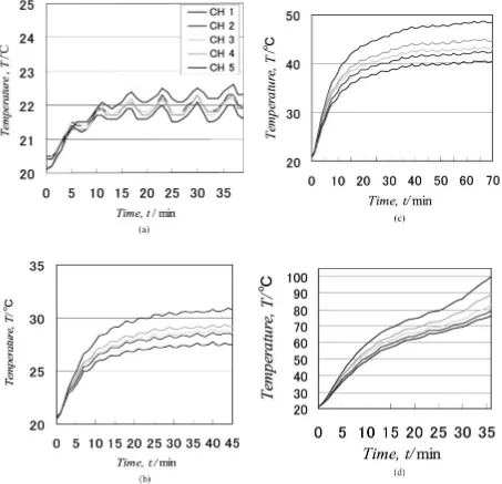
As described above, longer and more stable temperature control can be realized by using heating block 650, and more uniform temperature distribution within the block is pre-ferred. Figures 8(a) to (d) shows the temperature fluctuation inside a single block of 650. It can be seen that for 650, excellent temperature stability was obtained for applied voltage of 10 V, because the temperature measured at 5 measuring points (CH1–CH5) falls near 22C. At applied
voltage of 20 V, fair temperature uniformity was obtained; the temperature difference is 4C (27–31C). However, at
applied voltage of 30 V, the temperature difference amounts to 10C (39–49C) between CH1 and CH5. Under applied
voltage of 40 V, temperature overshooting occurs and is not preferred.
3.5 Temperature vs. time profiles of the heater block and conventional ceramic heater
Figure 9 shows the time necessary to reach temperatures between 23.8 and 33C for a conventional ceramic heater (commercially available ceramic heater for heating solders) and a woodceramic heater (carbonized at 650C), both under
Fig. 7 Change of surface temperature with passage of time for 650 (average of 5 measuring points).
[image:4.595.313.543.72.424.2]constant applied voltage and current of AC 10 V and 60 mA. Quick temperature rise under low power input is observed for woodceramic heaters; i.e., woodceramic heaters can attain the required temperature in about half the time necessary for ceramic heaters.
4. Conclusion
Woodceramic heating blocks suitable for low temperature heating,e.g., in biological incubator systems, were fabricated by carbonizing medium density fiberboard (MDF) impreg-nated with phenolic resin. Woodceramic heating blocks having lower water absorptivity were found to be favorably produced by carbonizing in the temperature range of 650– 800C. Furthermore, by optimizing conditions such as
applied voltage and block configuration, it has been found that stable heater operation can be realized by the single use of heater block carbonized at 650C; i.e., at 22C under applied voltage of 10 V, and at 27–31C under 20 V.
Fig. 8 (a) Temperature profile for 650, at 10 V. (b) Temperature profile for 650, at 20 V. (c) Temperature profile for 650, at 30 V. (d) Temperature profile for 650, at 40 V.
[image:5.595.73.526.75.512.2] [image:5.595.61.279.570.757.2]The advantages of the woodceramic heaters as compared with the conventional ceramic heaters are as follows: (1) Capable of quickly rising the temperature; (2) High stability at designated temperature; (3) Lower power consumption; and (4) Homogeneous and direct heating of the sample (free of air convection).
REFERENCES
1) T. Okabe and K. Saito: Jpn. Tokyo Kokai No. 1992-164806.
2) H. Iizuka, M. Fushitani, T. Okabe and K. Saito: J. Porous Mater.6(1999)
175–184.
3) K. Saito, K. Hokkirigawa, M. Otsuka, M. Fushitani and T. Okabe (Ed.): Woodceramics(in Japanese), (Uchida Rokakuho Publishing Co. Ltd., Tokyo, Japan, 1996).
4) T. Okabe, T. Hirose, R. Ozao, M. Otsuka, M. Mayuzumi, J. Tuzi, H. Chiba and S. Shibata: Trans. Mater. Res. Soc. Jpn.29(2004) 2431–2434. 5) K. Kakishita, S. Asai and T. Suda: Trans. Mater. Res. Soc. Jpn. 28
(2003), 229–232.
6) M. Miki, T. Kikuchi, S. Inada, M. Suzuki and J. Takada: J. Jpn. Soc. Powder Powder Metallurgy52(2005) 124–130 (In Japanese). 7) T. Hirose, T. Fujino, T. Fan, H. Endo, T. Okabe and M. Yoshimura:
Carbon40(2002) 761.