Progress on Composites with Embedded Shape Memory Alloy Wires
13
0
0
Full text
(2) 962. J. Schrooten et al.. formational behaviour and most particularly the thermomechanical behaviour for conditions encountered during processing and activation of these SMA composites. 2.1.1 SMA wire inventory The SMA wire selection started with quantifying the requirements of the desired wires. The main concern was that for the integration in composites the SMA wires should be as thin as possible. However, (i) the price per kg increases rapidly with decreasing diameter and (ii) the quality of SMA wires below 100 µm has not been sufficiently studied. Thus it was decided that the main SMA wire diameter would be 150 µm. With respect to the choice of composition, it was necessary for most applications in mind to choose a transformation temperature just above room temperature (313 to 323 K), so that the thermal cycling to activate the relevant component was as small as possible. Low hysteresis and a reproducible behaviour were also desirable. In addition, some superelastic wires were considered for energy absorption upon impact. Different types of SMA wires were evaluated: NiTi, NiTi-R-phase and NiTiCu. 2.1.2 SMA wire properties To enable the selection of a suitable SMA wire for a given SMA composite application, the wire properties had to be determined first. Since the information from the SMA suppliers was not sufficient to allow proper selection an extensive in-house evaluation was conducted. The transformational, thermomechanical and stability behaviour, and the surface characteristics were investigated. The transformational characteristics of the wires, including the transformation temperatures and heats, were determined using Differential Scanning Calorimetry (DSC). Transformation strains and stresses, Young’s modulus and electrical resistance were determined by thermomechanical analysis using a specially designed testing apparatus.3) Accurate thermomechanical experiments cannot be conducted by conventional tensile testing equipment due to the complex coupled strain and temperature requirements. This fully computerised equipment offers the possibility of complex coupled control of stress, strain and temperature and of real-time data acquisition and processing. Computer control strategies were developed for simulating the biasing effect of the matrix. The resulting quantitative SMA wire database could describe accurately the action of the SMA wires in the SMA composites during heating and cooling. The characterisation of the surface condition (roughness and chemical composition), which is an important parameter for the quality of the SMA wire (fatigue, etc.) and of the composite, was studied using two different methods: scanning electron microscopy (SEM) and X-ray photoelectron spectroscopy (XPS). It is worth mentioning that the wire surface condition affects the strength of the wire/resin interface, which, in turn, influences the functionality and durability of the composite. The stability of the thermomechanical behaviour of the SMA wires is influenced by many parameters, including the composition, the final processing and heat treatment, and the training procedure. Tests on the stability of the shape memory behaviour during short- and long-term cycling have been carried out on all types of SMA wires for different thermomechanical modes: (i) thermal cycling under constant load, (ii). strain cycling at constant temperature, and (iii) temperature cycling under constant strain. These experiments were also performed on the thermomechanical testing apparatus. 2.2 Host material selection 2.2.1 Epoxy resin The choice of the epoxy resin was critical for the production of the hybrid composites and the inherent co-operation of the constituent materials. The considered parameters were (i) a low curing temperature, yet a glass transition temperature well above the transformation temperature range, (ii) optical transparency of the resin to allow Raman measurements, (iii) the potential for B-stage prepregging, and (iv) a low cost. The LTM 217 resin produced by the Advanced Composites Group was selected and studied by means of IR-spectroscopy, Laser Raman Spectroscopy (LRS), Dynamic Mechanical Analysis (DMA) and Differential Scanning Calorimetry (DSC). Rheometry tests were also performed to study the curing kinetics and to establish the optimum curing conditions for the epoxy resin and the composite. Finally, standard mechanical tests were performed on the epoxy systems to derive the values of modulus, strain to failure and tensile strength. All composite specimens were made with the same resin, except the impact specimen (see Sec. 2.3.1). The cure cycle was determined with a ramp at 4 K/min to 343 K and 12 hours at 343 K, followed by a post cure with a ramp at 0.33 K/min to 413 K and 4 hours at 413 K, to reach a Tg between 418 K and 423 K and a stable thermal expansion behaviour. 2.2.2 Aramid fibre Aramid fibres were chosen due to their Raman response and their modulus compatibility with the embedded SMA wires. With respect to these criteria the Kevlar 29 by Du Pont was selected since it is a well-characterised and documented fibre, with a low modulus, and a negative axial coefficient of thermal expansion.4) Standard mechanical tests were carried out on Kevlar 29 monofilaments to determine their Young’s modulus, fracture strain and fracture strength. Mechanical tests were also conducted on a specially designed microextensometer, which has been constructed to apply an axial tensile load on single fibres or wires and to monitor simultaneously the mechanical and Raman response. From the recorded Raman spectra well-defined relationships of the peak shift for the 1611 cm−1 and 1648 cm−1 bands as a function of applied mechanical load were derived and were subsequently employed for the determination of stress and strain in the embedded fibres. These calibration curves were also employed for the determination of the internal stress distribution before, during and after wire activation in the SMA composite. During the SMA wire activation heat is generated in the wires and then dissipated into the hybrid composite. Thus the influence of temperature on the Raman spectra of Kevlar 29 fibres was a very critical parameter. In order to clarify the effect of temperature two different experiments were conducted. In the first one, the influence of temperature on the Raman response of free standing aramid fibres was investigated within the 223 to 473 K range. From the results it was evident that the 1611 cm−1 Raman band is strongly temperature dependent, while the 1648 cm−1 band could be considered as temperature unaffected within the examined range. In the second experiment the influence of temperature on the Raman.
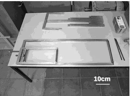
(3) Progress on Composites with Embedded Shape Memory Alloy Wires. stress coefficient was examined for both 1611 and 1648 cm−1 Raman bands. The experimental data led to the conclusion that the Raman stress coefficient is not affected by temperature for both bands. Thus a suitable methodology for evaluating the stress and temperature, independently, inside the composite at the microscopic scale was developed.5, 6) 2.3 Hybrid composite production 2.3.1 Standard SMA composite To produce SMA composites with pre-strained SMA wires special frames carrying pre-strained SMA wires at different volume fractions, size, spacing, etc. were designed and manufactured (small frame in Fig. 1). The frames enabled SMA wires to be wound around comb-like pins, 500 µm apart, situated at both ends of the frame. One of these combs could be moved in order to pre-strain and then hold the wires at the required pre-strain value during curing. The maximum number of wires possible was 2 wires/mm, but two frames could be superimposed to provide 2 layers of wires in the final product. The laminated assembly, which combines the Kevlar prepregs and the pre-strained SMA wires, was cured in an autoclave. The frame prevented the strain recovery of the pre-strained SMA wires during heating. After curing the frame was removed. The manufacturing route followed in this study offers unique advantages: a more homogeneous distribution of the aramid fibres around the SMA wires and, more importantly, a much better consolidation of the SMA wires. An example of a cured Kevlar composite containing strips of pre-strained embedded SMA wires is given in Fig. 2. These bulk samples were cut into separate composites (150 × 12 mm2 ) prior to testing. For all wire types unidirectional SMA composites were produced, with different SMA wire volume fractions, which were generated by wire spacing, number of wire layers and of prepreg plies, and with different pre-strain levels, ranging from no pre-strain to the maximal shape memory strain (8% for NiTi and 6% for NiTiCu). To perform impact experiments special SMA composites, with different SMA wire volume fractions, were produced. The samples (125 × 125 mm2 ) consisted of SMA wires em-. 10cm 10cm. Fig. 1 Comparison between the frames used for the production of the standard SMA composites (small frame) and for the production of the scaled model (big frame).. 963. bedded in a glass fibre epoxy matrix, covering a width of 16 mm. A Strafil G-EPI-140/142 glass fibre epoxy prepreg, from Hexcel Composites, was used. The following prepreg lay-up, [0◦ , 45◦ , 90◦ , −45◦ ]2s , which, from the literature,7) suggests a good resistance against delamination during impact, was used. This laminate offers the opportunity to use a variety of energies (both low and high) for the impact damage tests. The wires were aligned at different through thicknesses of the plate. The SMA impact composites were cured at 413 K for 20 minutes. In some experiments SMA glass fibre composites, with a lay-up identical to the Kevlar samples, were used as a comparison. 2.3.2 Aerodynamic SMA composites To allow the production of the aerodynamic profile model new frames were designed and built, based on the existing standard frames. Figure 1 makes a comparison between a standard frame (small) and the model frame (big). The big frame has a modular set-up to allow the production of SMA composites with different dimensions. The production route for the aerodynamic model was identical to that of the standard SMA composites. An example of a SMA composite produced for the skin of an aerodynamic profile is given in Fig. 3. 2.4 SMA composite characterisation The functional properties of SMA composites are directly related to the constraining behaviour that the composite matrix exerts on the SMA wire. SMA wires that are pre-strained and embedded in a constraining matrix, when heated, act against the surrounding matrix. Recovery stresses are gradually generated within the wires during heating and the strain recovery is delayed. This phenomenon is the basis for adaptive composites. Thus all SMA composites produced were subjected to a wide range of experimental techniques in order to characterise and understand the SMA composite behaviour. The transformational, dimensional, tensile and impact behaviour were investigated by standard testing techniques. The interfacial, internal stress and strain, thermomechanical and vibrational behaviour were tested using new or adapted techniques.. 5cm. Fig. 2 Bulk standard SMA composite samples..
(4) 964. J. Schrooten et al.. 10cm 10cm. Fig. 3 SMA composite skin of the aerodynamic profile.. 2.4.1 Standard testing techniques Differential Scanning Calorimetry (DSC) was used to investigate the transformation temperatures and heats of the SMA composites. The composites were cut into 0.5×0.5 cm2 pieces and weighed approximately 7 mg. A composite without SMA wires, which consisted of a matrix sample with similar weight to the matrix fraction of the specimen, was used as a reference.8) To evaluate the influence of the recovery stresses on the dimensional change of free standing SMA composites (10 × 15 mm2 ) a Thermomechanical Analyzer (TMA) was used. The ultimate strength and strain, and Young’s modulus of standard Kevlar 29-resin and SMA composites were determined by static tensile tests. The produced specimens were tested mechanically according the ASTM 3039 procedure. The impact performance of SMA composites was examined by incorporating superelastic and martensitic NiTi, NiTiCu and steel wires into a glass epoxy matrix. The impacting apparatus used was an in-house built system. The impact energies exerted on the specimens were 6 J, 12 J and 18 J. It should be noted that techniques that are employed to analyse impact damage for metallic specimens should be used here with caution. Composites are much more complex material systems than metals, and therefore different parameters are important.9) The mechanical fatigue behaviour was examined on a four ply SMA composite laminate with dimensions 120 × 12 × 0.5 mm3 . The embedded SMA wires were NiTiCu with 3% pre-strain. Cyclic fatigue was performed under extreme loading conditions namely in a strain-controlled mode with 2 Hz frequency and 0.7% to 1.8% peak to peak strain. 2.4.2 Novel testing techniques (1) SMA wire-epoxy interface evaluation (a) Pull-out A special pull-out testing technique was designed to test the interfacial shear strength between the LTM217 resin and the SMA wires. Epoxy disks, with a single SMA wire embedded in the centre, were made using silicon moulds. For each wire type, samples with six different embedded lengths were produced. An UTS tensile testing machine was used to determine the maximum pull-out force. The experimental shear strength was calculated from the pull-out force at failure, the. wire diameter and the embedded length.10) (b) Laser Raman Spectroscopy (LRS) A new method for assessing the integrity of the fibre/matrix interface in plain Kevlar 29/epoxy composites by means of LRS was developed. In the stage of specimen preparation and before autoclave curing, a small surgical cut was introduced in the upper prepreg layer. As a result a discontinuity was induced in a few number of fibres and after curing the created gap was filled with resin. The presence of this type of fibre(s) discontinuity was not expected to affect at all the mechanical properties of the composite laminate. This technique allowed the recording of the stress transfer profile at small deformations prior to fibre fracture, which occurs at relatively high strains for Kevlar fibres (∼ 3%). By focusing the laser beam on the fibre at the discontinuity and scanning along the fibre the axial force could be measured. By considering a simple balance between the shear forces at the interface and the axial forces in the fibre, the interfacial shear stress distribution was obtained.11) This methodology was applied in a four-ply Kevlar 29/epoxy resin composite specimen with dimensions of 125× 12 mm2 . A specially designed mechanical frame was constructed for applying tensile load in the specimen. The recording of the actual levels of applied strain were found by the Raman response as described below (3).12, 13) (c) Differential Scanning Calorimetry (DSC) It was found that the transformation heats measured by DSC decrease substantially with increasing pre-strain of the embedded SMA wires.8) This is explained (i) by considering the difference between self-accommodating martensite (SAM), which linearly decreases with pre-strain, and preferentially oriented martensite (POM), which linearly increases with pre-strain, and (ii) by applying some basic principles of the thermoelastic martensitic transformation. The SAM is not significantly influenced by the process of pre-straining and embedding in the matrix and can transform freely into austenite upon activation. The constraining matrix, however, suppresses very effectively the progress of the transformation of the POM variants upon activation. If the interface partially or totally debonds under a thermal load, the constraining effect of the matrix will partly or totally disappear. As a result, the stabilised POM is no longer fully constrained, can freely transform into austenite and will show an endothermic peak on the DSC curves. Thus DSC analysis can be used to investigate the integrity of the SMA composite and define a temperature window in which the SMA composite can be used safely.14) (2) Thermomechanical behaviour The thermomechanical (and hence the functional) properties of SMA composites are a direct outcome of the peculiar thermomechanical behaviour of the SMA wires. Pre-strained SMA wires operate during heating against the elastic stiffness of the constraining aramid-epoxy matrix. Since the strain recovery of the SMA wires is biased during heating, high recovery stresses are gradually generated by the SMA wires (and strain recovery of the SMA wires is delayed). Vice versa, during cooling the recovery stresses decrease after overcoming a temperature hysteresis (and the SMA wires become strained). A remarkable feature of the literature on SMA composites is that quantitative data on the generation of recovery stresses.
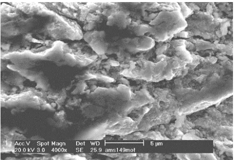
(5) Progress on Composites with Embedded Shape Memory Alloy Wires. are very scarce and of dubious quality. The same testing apparatus as for the SMA wires was adapted to investigate the thermomechanical behaviour of the SMA composites (see Sec. 2.1.2 and 3)). (3) Internal stress and strain distribution For the determination of the stress distribution in the SMA composites during and after the SMA wire activation, a new experimental set up was constructed. This set up allowed the recording of the Raman spectra during SMA wire activation and the simultaneous control of the wire temperature. The level of activation of the embedded SMA wires was controlled electrically and the induced mechanical stresses in the aramid fibres were obtained by means of LRS. The observed influence of temperature on the recorded Raman spectra of the aramid fibres required the deconvolution of the mechanical and thermal contributions. The methodology developed here allowed the simultaneous determination of mechanical stress and temperature inside the SMA composites with a spatial resolution of 1–2 µm. LRS measurements combined with a suitable statistical analysis provided accurate values for the residual stresses. Raman sampling was performed on a line normal to the fibre direction on the surface of the specimen and at steps of approximately one fibre diameter.5) (4) Vibrational properties The vibration response of SMA composites activated by electrical current heating was measured using a specially designed set-up. It is composed of a U-shaped sample holder, a shaker, a Laser Doppler detector and a computer to record and treat the measured signal. The composites are mounted on the holder, which allows the measurement of the force exerted by the composite on the holder arms through a wheatstone bridge. The entire sample can additionally be pre-deformed. The SMA wires are heated incrementally by direct electrical current and cooled down by convection at the matrix surface after switching off the current. The sample holder is fixed on a shaker, which produces given frequency vibrations perpendicular to the plane of the composite. The amplitude of the imposed vibration and the amplitude response of the sample are measured with the laser using the Doppler effect.15) 3. Results & Discussion 3.1 SMA wire characterisation A limited overview of the typical results obtained from the SMA wire evaluation is given below. It contains information about the transformational, surface and thermomechanical behaviour. All results were systematically applied to select a suitable SMA wire for a given SMA composite design. The influence of thermal treatment and cycling on the transformation temperatures and heats of the SMA wires has been investigated and resulted in valuable knowledge for the SMA composite production. The presence of an oxide top layer on the SMA wires is believed to be beneficial for the adhesion to the epoxy. Most SMA wires have an oxide surface layer after drawing and heat treatment, ranging from a thin good adhering one (Fig. 4) to a thick loose coating (Fig. 5). If the oxide layer is removed by polishing or etching, the resulting wire surface is very smooth, which is not beneficial for wire/polymer adhesion. The properties of the oxide layer are hardly influenced by the thermal cycling of the wires. XPS-. 965. Fig. 4 Surface of a NiTi12 mass%Cu wire, 35% cold-worked and straightened, oxide surface, as-received from Memry.. Fig. 5 Surface a NiTi10 mass%Cu wire, straight annealed, oxide surface, as-received from AMT.. measurements confirmed the presence of the oxide layer. All these results are crucial for the interpretation of the interface characterisation and the selection of good adhering SMA wires. The thermomechanical analysis, giving information on the stress-strain-temperature behaviour of all available SMA wires, provides a powerful tool for the selection of the most appropriate wire for a given SMA composite application. Due to the extensive nature of these experiments only one example is shown. Figure 6 represents the stress-temperature behaviour (ε = cte) of a NiTiCu wire. From this graph three characteristics of the temperature-stress behaviour of NiTiCu SMA wires can be concluded: (i) The recovery stress of the 1% pre-strained wire starts at the As temperature of NiTiCu. For the wire pre-strained to 6%, the recovery stress starts to increase from the beginning of the heating process, even when the temperature is below As . A possible explanation for this phenomenon is the twostage transformation of the TiNiCu wire, which is influenced by the pre-strain level.16) (ii) Upon cooling, the recovery stress decreases with temperature, but does not go back to the initial stress level. Instead, the recovery stress falls back to a lower stress level at the end of the cooling process. For small pre-strain levels (1% to 3%), the recovery stress reaches zero at RT. For large pre-strain levels (4% to 6%), the recovery stress remains at.
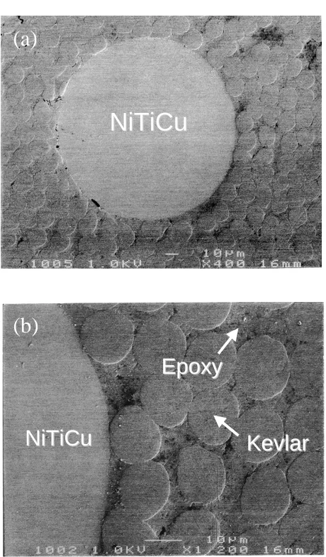
(6) Recovery Stress,. / MPa. 966. J. Schrooten et al. 700. 10. 600. 9. 500. 8. 400. NiTi. 7. 300. NiTiCu. 6. 200. 5. 100. 4 0. 3 -100 300. 320. 340. 360. 380. 400. 420. Temperature, T / K. Fig. 6 The recovery stress of NiTi12 mass%Cu wires. The wires were pre-strained at RT and then the strain was kept constant without unloading before being thermally cycled between RT and 413 K and further cycled between RT and 383 K. The solid circle on each curve denotes the starting point of the heating process.. 2. NiTi-R-phase. 1 0 0. 20000. 40000 60000 Time, t / s. 80000. Fig. 7 Short-term thermal cycling (30 cycles) of NiTi, NiTi-R-phase and NiTiCu under a constant load of 283 MPa.. a nonzero stress level at RT. In the second and further cycles between RT and 383 K, the recovery stress loop is stabilised. (iii) The rate at which the recovery stress increases with temperature decreases with increasing pre-strain. Similar conclusions were drawn for the other SMA wires and test modes (stress-strain, strain-temperature).16) The results allow understanding and rather accurate prediction of the generation of recovery stresses by SMA wires in complex constraining conditions, i.e. similar to the action of SMA wires in matrix materials. An important result is that the NiTiCu martensitic wires show less hysteresis and can generate substantially higher stresses than binary NiTi martensitic wires, which are the only alloys investigated in most other projects on adaptive composites. Increasing the pre-strain can narrow the hysteresis of NiTi substantially. The observations also confirm that SMA wires showing the R-phase transformation could be particularly effective for on-off control of adaptive composites. Finally the stability (short- and long-term) of the shape memory behaviour under different modes was investigated. Figure 7 shows a short-term cycling of the three different wire types. An important result is that NiTiCu is much more stable than any binary NiTi. In general SMA wires are much more stable in constant strain mode than in constant stress mode. The practical consequence is that the tolerable stress levels in SMA wires embedded in composites can be substantially higher than originally expected. The tests have also confirmed that the behaviour associated with the R-phase transformation is extremely stable. The results finally indicate that the quality of the SMA wire surface is of extreme importance. SMA wires with a very rough surface fracture after a very limited number of cycles. The combination of all these series of experiments provides very important basic information on the effect of curing treatments on the shape memory behaviour. It has been confirmed that the proposed curing treatment (up to 413 K) has only minor effects on the SMA wires. The results also indicate that significantly higher curing temperatures could be allowed, especially in the case where low pre-strains are used. Time effects resulting in creep or stress relaxation of the SMA wires. can in general be neglected during curing at such temperatures. There are several indications that the curing treatment can even stabilise the shape memory behaviour, which might open interesting perspectives. From the SMA wire survey and evaluation it can be concluded that NiTiCu is the most suitable wire composition for the SMA composite applications investigated in this project. The wire generates high recovery stresses, has a stable shape memory behaviour and a very narrow hysteresis loop and shows a good potential for adherence to the selected epoxy through its stable oxide layer. 3.2 SMA composite characterisation 3.2.1 Quality of SMA composites The SMA composite production process resulted in the successful integration of the SMA wires into Kevlar or glass epoxy matrix. Figure 8 shows a cross-section of a standard SMA composite. From this picture it can be seen that all components are combined into one integrated structure. Standard testing techniques were used to investigate the mechanical properties and the integrity of the composites. Table 1 shows the Young’s modulus and fracture strength of SMA composites in comparison to plain Kevlar composites. Figure 9 shows the “impact performance map” of several SMA composites in comparison to other composites. This map combines the PDA and the IEC slope. The PDA slope is defined as the slope of the damage area vs incident energy and is a measure of damage resistance. The higher the PDA slope the more susceptible the material is to damage. The IEC slope is defined as the slope of the absorbed energy vs incident energy and is a measure of the materials energy absorption capacity. The higher the IEC slope for a material, the better the internal damping and impact energy absorption. The impact performance map showed that superelastic SMA composites exhibit good damping and energy absorption capabilities compared to embedded NiTiCu or steel composites, as well as a reasonably low damage accumulation after impact. Due to the limited amount of incorporated SMA wires (1.8 vol%) the in-.
(7) Progress on Composites with Embedded Shape Memory Alloy Wires Table 1. 967. Young’s modulus, fracture strength and strain of SMA composites.. Specimen E max /GPa. Young’s modulus, E min /GPa. E 0.01a /GPa. Fracture strength, σ /MPa. Fracture strain, ε/%. Aramid fibre/epoxy resin (4 plies). 53.4 ± 2.0. 42.5 ± 1.0. 44.7 ± 1.5. 943 ± 87. 2.1 ± 0.2. SMA/Aramid fibre/epoxy resin (4 plies, 20 wires). 58.9 ± 1.6. 43.8 ± 0.7. 44.2 ± 0.8. SMA/Aramid fibre/epoxy resin (2 plies, 20 wires). 46.4 ± 4.5. 29.4 ± 9.8. 45.0 ± 3.2. a This. 1094 ± 1. 2.3 ± 1.6. 782 ± 39. 2.0 ± 0.1. value of E corresponds to a strain of 0.01%.. 35. PDA Slope, dA.dE -1 / mm2.J. -1. (a). NiTiCu. no wires. 30 1 wire/mm. 25 20. NiTiCu. 15. 0.5 wires/mm 2 wires/mm. 10 steel 5 0 0. 0.2. 0.4. 0.6. 0.8. 1. 1.2. IEC Slope Fig. 9 Impact performance map. (All samples only showing the wire density are superelastic SMA wires).. (b) Epoxy NiTiCu. Kevlar. Fig. 8 Cross sections of a Kevlar fibre composite with embedded 3% pre-strained TiNiCu wires, showing the fibre distribution around a wire, and the soundness of the composite.. fluence of the wires on the total impact performance is somewhat minimal. In mechanical fatigue testing the first event of failure manifested itself after more than 700000 cycles at a stress of 446 MPa, while the initially applied stress was 614 MPa. The specimen exhibited longitudinal splitting as often happens. in unidirectional aramid fibre/epoxy resin composites, even though a high tensile stress of 446 MPa was still attained by the specimen up to 860000 cycles. These results are indicative of the high fatigue performance of the SMA composites. From all experiments mentioned above it is concluded that SMA composites with excellent mechanical properties and functional integrity can be produced. These properties themselves do not generate a new class of materials and do not bring out the special properties of SMA wires. These unique properties will be discussed in what follows. 3.2.2 Transformation of constrained SMA wires The thermomechanical and functional properties of the SMA composites are directly related to the reversible martensitic transformation in the SMA wires. The gradual transformation and the related strain recovery are hampered by the presence of the stiff host-composite. The constrained martensitic transformation of pre-strained SMA wires is summarised in Fig. 10. After pre-strain, the self-accommodating martensite (SAM) transforms into preferentially oriented martensite (POM) ((a) to (b)). In a constrained heating process, POM only partly transforms into the parent phase (P), and the recovery stress is gradually building up ((b) to (c)). As a result, the remaining POM is further deformed by the recovery.
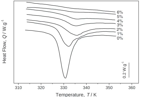
(8) 968. J. Schrooten et al.. (a). Table 2 Intrinsic shear strength SMA wire-epoxy interface. All wire were tested as-received (oxide surface), otherwise the surface treatment is indicated.. SAM. Wire type. (b). POM. (c). P. (d). SAM. NiTi R-phasea NiTi0.20 mass%Cra NiTiCua NiTib (pickled surface) NiTib (polished surface) NiTib NiTiCuc NiTiCud. Fully oriented martensite. Fully oriented martensite. 0.2 W.g. -1. Heat Flow, Q / W.g. -1. Fig. 10 Constrained martensitic transformation of SMA wires.. 310. 320. 330. 340. 350. 360. Temperature, T / K. Fig. 11 DSC heating curves of NiTiCu composites (wire pre-strain levels are indicated).. stress and finally becomes fully oriented martensite (c). Upon cooling, the parent phase transforms into SAM, and the fully oriented martensite remains unchanged. In the second and the following constrained thermal cycles, SAM and fully oriented martensite are clearly distinguished (d). The reverse transformation of SAM does not generate any recovery stress and thus can proceed similar with that in a free condition. Therefore, the reverse transformation of SAM can be easily detected by DSC and electrical resistance measurement. The reverse transformation of POM is accompanied by an increasing recovery stress, and thus becomes quite slow and spreads over a large temperature range. This kind of transformation is imperceptible by DSC and electrical resistance measurement. Figure 11 shows the DSC characteristics of SMA elements embedded in composites. If the SMA elements are not prestrained, only SAM is involved in the reverse transformation, and the reverse martensitic transformation thus can proceed just as in a free condition. If the SMA elements are prestrained prior to constraining, both the SAM and POM are involved in the reverse transformation, but only the SAM shows an endothermic peak on the DSC curves. The reverse transformation of the POM spreads over a large temperature range and does not show perceivable peaks on the DSC curves. The area of the endothermic peak (transformation enthalpy) decreases with pre-strain level, and reaches zero at the maximum shape memory strain (6% for NiTiCu).8). a Thomas. Intrinsic shear strength, τi (average)/MPa 26.05 72.73 43.29 17.02 18.96 23.93 4.63 87.19. Observations Thin oxide layer Oxide layer Rough oxide layer Etched Polished Thin oxide layer shiny surface Cohesive failure, rough oxide layer. Bolton b SMA-Inc. c Memry d AMT. 3.2.3 Interfacial properties (1) Pull-out The experimental shear strength, given by the failure of the interface, combines the contributions of an intrinsic shear strength, which is an indicator of the interface quality, and a thermo-elastic (or thermo-visco-elastic) shear stress, which is induced during processing of the material, taking into account diverse geometrical factors. A model was used to calculate the intrinsic shear strength, which is independent of the embedded length.17) The results were satisfactory, although some deviations were observed for the wire types with a thick (rough) oxide layer on their surface. For these cases the calculation of an “intrinsic” interfacial shear strength was not appropriate, because it exceeded the shear strength of the bulk material. This was confirmed by observation of the fracture surfaces, where cohesive failure was found for the wires with a thick oxide layer. As expected, the polished and etched wires had a lower interfacial strength than in their oxidised state. It is interesting to note that NiTiCu wires a priori similar from the manufacturing data reach different values of shear strength, because their surface aspect is in fact quite different, in terms of roughness and oxide thickness. All the results for the intrinsic shear strength for each wire type are summarised in Table 2. In general, adhesion between the epoxy resin and the wires is sufficient for an adequate stress transfer. On NiTiCu wires pull-out tests under pre-strained (3%) condition, imitating the composite manufacturing route, were performed. Additionally, some of the samples were submitted to one or more activation cycles. The results showed that the interfacial shear strength is slightly lower than in the unstrained tests. However, no significant difference in shear strength between non-cycled and cycled samples was found. (2) LRS In the LRS-methodology the applied tensile strain was monitored using conventional strain gauges, but the recording of the actual levels of applied strain were found by subtracting the Raman wavenumber shift distribution of the embedded fibres in the composite from the corresponding distribution of free-standing fibres in air. Then, the resulting distribution was divided by the Raman wavenumber sensitivity factor for stress or strain and was thus converted to stress or strain distribution. The mean values of each strain distribution represented.
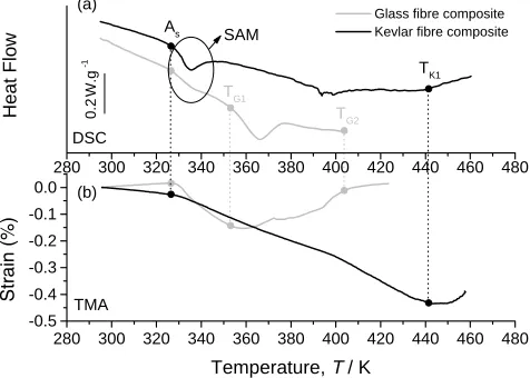
(9) Progress on Composites with Embedded Shape Memory Alloy Wires 1200. 3.959 J.g. -1. -0.12. 800. Spline fit. Heat Flow, Q / W.g. / MPa. First heating Second heating. -0.11. (a). 1000. Raw data. 600. Stress,. 969. 400 200. -1. -0.13 -0.14 -0.15 -0.16 -0.17. 0. -0.18 280. -200 0. 100. 200. 300 400. 500. 600. 700 800. 900 1000. 300. 320. 340. 360. 380. 400. 420. Temperature, T / K. Distance From Fibre Discontinuity, l / m. (a) As -1. (b). Glass fibre composite Kevlar fibre composite. SAM. TK1. 0.2 W.g. 16 14 12 10 8 6 4 2 0 -2 -4 -6 -8 -10 -12 -14 -16. Heat Flow. Interfacial Shear Strength, ISS / MPa. Fig. 13 Enthalpy change of standard SMA composites in two consecutive thermal cycles.. TG1 TG2. DSC 280 300 0.0 (b) -0.1. 320. 340. 360. 380. 400. 420. 440. 460. 480. 320. 340. 360. 380. 400. 420. 440. 460. 480. -0.2 -0.3 -0.4. 0. 100. 200. 300. 400. 500. 600 700. 800. 900 1000. Distance From Fibre Discontinuity, l / µm. TMA -0.5 280 300. Temperature, T / K. Fig. 12 Axial fibre stress (a) and corresponding ISS profile (b) for a strain level of 0.4%.. Fig. 14 Comparison between the DSC (a) and TMA (b) results of Kevlar fibre and glass fibre composites with embedded 3% pre-strained TiNiCu wires.. the applied strain levels, which were 0.4, 0.7 and 0.9%. An example of the measured axial fibre stress and the corresponding interfacial shear stress (ISS) profile is shown in Fig. 12. It is worth noting that the LRS results are comparable to the pull-out results. (3) DSC For a SMA composite, if the interface partially or totally debonds under a thermal load, the constraining effect that the matrix imposes on the SMA elements will partly or totally disappear. As a result, the stabilised POM can freely transform into the parent phase and shows an endothermic peak on the DSC curves. Figure 13 shows the DSC results of SMA Kevlar fibre composites in two consecutive thermal cycles. During the first heating, a first, small endothermic peak appears on the DSC curve because of the reverse transformation of SAM. Upon further heating, the interface debonds little by little, and POM transforms into parent phase step by step, as shown by the small sharp peaks indicated by the arrows in the figure. As a result, the amount of SAM increases and the transformation enthalpy in the subsequent heating cycle will increase. The interfacial bond strength will significantly influence the transformation characteristics of the embedded SMA elements. Figure 14 shows a comparison between the DSC. (a) and TMA (b) results of Kevlar fibre and glass fibre composites with 3% pre-strained NiTiCu wires. For the Kevlar composites, some little peaks appear on the DSC curve at around 390 K upon further heating, which might indicate little debonding somewhere at the interface at that temperature. The composite twisted at 440 K (TK1 ) due to high temperature and large recovery stresses. For glass fibre composites, one can see that a large endothermic peak appears at TG1 (around 350 K) and that the thermal contraction is inverted rapidly. From TG2 (around 400 K) onwards, the composite begins to expand at a rate equal to that below As , indicating a total failure of the SMA-epoxy interface. This comparison shows the influence of the epoxy choice on the thermal integrity of the SMA composite. 3.2.4 Activation of free standing SMA composites (1) Internal stress measurement by LRS The performed tests showed the presence of weak compressive loads in the hybrid composites, which can be attributed to curing conditions during the preparation of the composites. Furthermore there is a strong indication that increasing the wire volume fraction results in a decrease of residual stresses. This is a direct consequence of the stresses developed during curing, since the constrained wires are pre-.
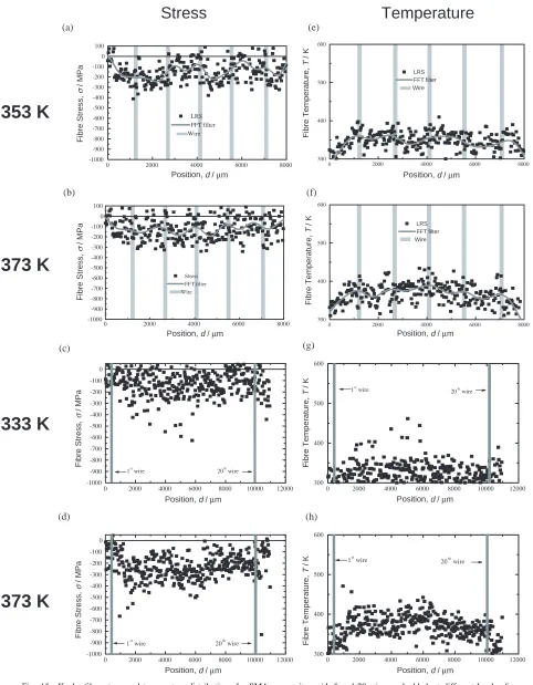
(10) 970. J. Schrooten et al.. vented from contraction during heating. During activation the generated stresses on the wires are depending on both the SMA volume fraction and the level of activation. Increasing the wire volume fraction results in the generation of higher stresses, but also in a more complex stress distribution, inside the specimen, due to the wire-to-wire interaction. The determined distributions suffer from scattering, since the recorded data reflect the response of individual Kevlar fibres located at varying distances from the wires. In an attempt to reduce the resulting noise a Fast Fourier Transform technique was developed and applied. Figure 15 shows an example of the recorded fibre stress and temperature distributions across the SMA wire direction. By conducting stress measurements along the wire direction a mean value of transmitted stresses as function of the nominal SMA wire volume fraction was estimated. These mean stress values (along the wire) were of the order of 150–200 MPa, independent of the wire volume fraction, and corresponded to the stresses generated by an individual SMA wire.18) (2) Strain behaviour In general after the first thermal cycle, the NiTiCu SMA composites show a stable behaviour. From Figs. 14 and 16, which show the temperature-strain behaviour of SMA glass epoxy composites, four major characteristics of the strain behaviour can be found. (i) For small pre-strain levels (1 to 3%) the composites show a positive thermal expansion before As , due to the thermal elongation of the glass fibre. The Kevlar composites initially contract (Fig. 14(b)). When the temperature exceeds As , the recovery stress gradually builds up and the composites show a strong thermal contraction with increasing temperature. For large pre-strain levels (4 to 6%), the composites begin to contract from the very beginning even when the temperature is below As , which is thought to be the result of the development of recovery stress below As for large pre-strain levels (see Sec. 3.1,16) ). (ii) The As temperature decreases gradually with prestrain level. This is confirmed by DSC experiments and is thought to be the result of plastic deformation induced in the previous thermal cycle. (iii) The strain-temperature hysteresis decreases with increasing pre-strain. The two way shape memory effect (TWSME) of the NiTiCu wire is thought to be responsible for this change. For wires with small pre-strain levels, the TWSME may play an important role in the behaviour of the composite and thus the strain-temperature loops are similar to the TWSME strain loop. This influence decreases with increasing pre-strain. (iv) The contracting strain rate decreases with increasing pre-strain. This phenomenon is related to the decrease of the stress rate of the recovery stress with pre-strain. Taking into account the thermal integrity of the SMA composites it is concluded that small pre-strain levels are more suitable for large dimensional change of the SMA composites in a defined temperature range.14, 16) 3.2.5 Activation of clamped SMA composites (1) Stress generation The experimental results confirm that the knowledge gained through the thermomechanical analysis of the SMA wires can be extrapolated to SMA composites, taking into ac-. count the design properties of the composites (matrix materials, wire density, . . . ). Increasing the volume fraction can significantly increase recovery stress levels of the composite, as shown in Fig. 17. It was also found that the pre-strain level of SMA wires does not effect significantly the temperaturestress behaviour of SMA Kevlar fibre composites. Similarly to the SMA wires it was found that the stress rate decreases with increasing pre-strain. Finally, it is worth adding that stresses over 100 MPa can be generated by the SMA composites. After an initial thermal cycle the SMA composites behave in a stable and reproducible way. (2) Vibrational response All SMA composites subjected to vibrational analysis showed a shift in the resonance frequency upon activation, as shown in Fig. 18. The absolute resonance frequency depends on the dimensions of the sample and on the experimental setup. Therefore, the frequency shift is used to evaluate the vibrational response. Figure 19 shows that the frequency shift increases with temperature and wire density and that at the As temperature the slope of the frequency shift changes. No significant dependence of the resonance frequency on the wire pre-strain was found. These results are similar to the stressstrain response results reported in (1). As a consequence, a simple elastic vibrational model could be used to correlate fairly well the axial stress exerted on the clamps with the vibration frequency shift. Hence, if the prediction of the composite strain or recovery stress response is possible, the resulting frequency shift upon activation can be predicted as well, knowing the geometry of the sample.19–21) 3.3 Composite design The extensive characterisation of SMA wires, matrix materials and SMA composites resulted in a number of important guidelines for the design of SMA composites. The success of a SMA composite depends on the selection of a proper matrix and SMA wire combination. The NiTiCu-Kevlar epoxy combination was found to be suitable. A good knowledge of the thermomechanical SMA-behaviour is mandatory to assist the selection process. A thin well-adherent oxide surface layer on the SMA wires seems to provide the best adhesion and thus stress transfer. The SMA composite curing procedure as well as the material lay-up are of the outmost importance. Putting a pre-strain on the SMA wires is recommended, for easy handling during the SMA composite production and for attaining suitable properties. Due to the presence of elevated temperature during activation, it is of crucial importance that the Tg is as high as possible and that the resin is fully cured. The temperature window in which a SMA composite can be used safely must be defined. Otherwise composite degradation can appear during service. The wire positioning does not seem to have a strong influence as long as they are symmetrical to prevent bending of the sample. The impact performance is an exception to this statement. Both wire position and pre-strain have a strong influence on the impact quality of the composite. The wire volume fraction exerts a strong influence on the functional properties. After a first thermal cycle the composites have a stable behaviour. Subsequent cycling in a similar temperature window will not enhance possible initial degradation. Only a limited relaxation was observed and no degra-.
(11) Progress on Composites with Embedded Shape Memory Alloy Wires. Stress. 971. Temperature. (a). (e) 600. Fibre Temperature, Fibre Temperature, T/K T / K. 100. Fibre / MPa Fibre Stress, Stress, / MPa. 0. 353 K. -100 -200 -300 -400 -500 LRS FFT filter Wire. -600 -700 -800. LRS FFT filter Wire. 500. 400. -900 -1000. 300. 0. 2000. 4000. 6000. 0. 8000. 2000. 4000. Position, d / m. (b). 8000. 6000. 8000. (f) 600. 100. Fibre Fibre Temperature, Temperature, T / K T / K. Fibre Stress, Fibre Stress,/ MPa / MPa. 0. 373 K. 6000. Position, d / m. -100 -200 -300 -400 -500 Stress FFT filter Wire. -600 -700 -800. LRS FFT filter Wire. 500. 400. -900 -1000. 0. 2000. 4000. 6000. 300. 8000. 0. 2000. 4000. Position, d / m. Position, d / m. (g). (c). 600. Fibre T/ K FibreTemperature, Temperature, T/K. 0. 333 K. -200. st. 1 wire. th. 20 wire. o. FibreStress, Stress, / /MPa Fibre MPa. -100. -300 -400 -500 -600 -700 -800 st. th. 1 wire. -900. 20 wire. -1000. 500. 400. 300 0. 2000. 4000. 6000. 8000. 10000. 12000. 0. 2000. 4000. 6000. 8000. 10000. 12000. 10000. 12000. Position, d / m. Position, d / m. (d). (h) 600. 0. FibreTemperature, Temperature, T T / K Fibre /K. 373 K. -200. st. th. 1 wire. 20 wire. o. FibreStress, Stress, / /MPa Fibre MPa. -100. -300 -400 -500 -600 -700 -800 st. -900. th. 20 wire. 1 wire. 500. 400. 300. -1000 0. 2000. 4000. 6000. 8000. 10000. Position, d / m. 12000. 0. 2000. 4000. 6000. 8000. Position, d / m. Fig. 15 Kevlar fibre stress and temperature distributions for SMA composites with 5 and 20 wires embedded, at different levels of activation (TC: thermocouple).. dation at high temperature was found. To set-up a design tool that can predict the thermomechanical behaviour of SMA composites a model and accompanying software program, called RCLOOP, were developed.22) The model produces a very accurate simulation of the com-. plex hysteresis and thermomechanical SMA behaviour and can handle the behaviour of a complete SMA composite. A comparison with the experimental results showed that the program is a powerful tool to predict the thermomechanical behaviour of SMA wires and composites and to design these.
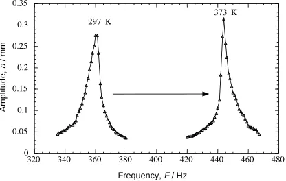
(12) 972. J. Schrooten et al. 100. 0.0002. Strain. Frequency Shift, H / Hz. 20 wires 80. 40 5 wires 20. 0. 300. 310. 320. 330. 10 wires. 60. 300. 340. 320. 340. 360. 380. Temperature, T / K. Temperature, T / K. Fig. 16 The stabilised thermal strain loops of the SMA composites when thermally cycled between RT and 343 K. The pre-strain levels are indicated in the figure. The arrows in the figure indicate the temperatures at which the slope of the heating curve changed.. Fig. 19 Resonance frequency shift as a function of temperature for composites with a constant thickness but different number of wires (20 wires corresponds to 5% volume fraction wires).. 120. Recovery Stress,. / MPa. 100. 80. 60. 40. 20. 0 280. 300. 320. 340. 360. 380. 400. Temperature, T / K. Fig. 17 The recovery stress of SMA-Kevlar composites with different volume fractions. 100% wire density equals 11.8% absolute wire volume fraction.. 10cm. 0.35 373 K 297 K. Amplitude, a / mm. 0.3 0.25. Fig. 20 Fully assembled aerodynamic SMA composite mounted inside the test rig.. 0.2 0.15 0.1. stantially higher level enabling a first step towards an industrial application.. 0.05 0 320. 340. 360. 380. 400. 420. 440. 460. 480. Frequency, F / Hz. Fig. 18 Resonance frequency of a clamped composite measured at room temperature and after the thermal activation of the SMA wires.. composites.23) The SMA composite design knowledge resulted in the fabrication of an aerodynamic model, shown in Fig. 20. The vibrational test results complied very well with intended dynamic behaviour and showed that the scaled model is stable and that its vibration properties are a function of the SMA wire activation. This industrially oriented and original realisation proved that the above mentioned achievements have brought the knowledge on SMA composite design to a sub-. 4. Conclusion The general objective of this basic research project was the material development and characterisation of adaptive composites with embedded SMA wires. All steps from the selection and characterisation of the material constituents up to the development of a simple, larger-scale laboratory model were followed. It can be concluded that the research of SMA composites has taken a significant step forward. SMA composites could be successfully produced. They showed an activation behaviour, which is consistent with the model. This latter predicts the thermomechanical behaviour of SMA wires and, with a simple force balance, the resulting composite behaviour. The issues of interfacial quality, internal stress dis-.
(13) Progress on Composites with Embedded Shape Memory Alloy Wires. tribution and reproducibility of the behaviour were also addressed. Additionally, major technical achievements were obtained in the course of the project, such as the manufacturing route of large, curved shapes with 2 layers of embedded SMA wires. In conclusion, the design and manufacture of active composites based on SMA wires is now a reality, which is currently being implemented in industrial practice. Acknowledgements The ADAPT project was funded by the European Commission, in the Industrial and Materials Technologies research and technological programme. The authors especially would like to thank all scientists who were involved in this project: Antonio Baltá-Neumann, Magdalena Parlinska, Jacques-Eric Bidaux, Dimitris Bollas, Nick Lekatsas, Kelly Ann Tsoi, Yanjun Zheng, Gidnahalli Dayananda, David Vokoun, Petr Šittner and Rudy Stalmans. The industrial partners of the ADAPT-project, being the European Aeronautic and Space Company (EADS), Daimler-Chrysler (DC) and British Aerospace (BAe), are also acknowledged for their collaboration. REFERENCES 1) R. Gotthardt, P. Scherrer and R. Stalmans: Mater. Sci. Forum 327–328 (2000) 83–90. 2) http://www.mtm.kuleuven.ac.be/Research/ADAPT/index.html. 3) R. Stalmans, J. Van Humbeeck and L. Delaey: Acta Mater. 40 (1992) 501–511. 4) Yang H.H.: Kevlar Aramid Fibre (John Wiley & Sons, 1993). 5) G. C. Psarras, J. Parthenios and C. Galiotis: J. Mater. Sci. 36 (2001) 535–546.. 973. 6) J. Parthenios, G. C. Psarras and C. Galiotis: Compos. Part A 32 (2001) 1735–1747. 7) G. Clark: Compos. Part A 20 (1989) 209–214. 8) R. Stalmans, K. A. Tsoi and J. Schrooten: Proc. of SPIE, Vol. 4073, ed. by P. F. Gobin and C. Friend, (2000) pp. 88–96. 9) V. M. Karbhari: J. Mater. Sci. 32 (1997) 4159–4166. 10) J. A. Balta, V. J. Michaud, M. Parlinska, R. Gotthardt and J.-A. E. Månson: Proc. of SPIE, Vol. 4333, ed. by C. S. Lynch (2001) pp. 377– 386. 11) C. Galiotis: Micromechanics of reinforcement using laser Raman spectroscopy, in Microstructural characterisation of fibre-reinforced composites, ed. by J Summerscales, (Woodhead pub. Co., 1998). 12) J. Parthenios, D. G. Katerelos, G. C. Psarras and C. Galiotis: Eng. Fract. Mech., in press. 13) G. C. Psarras, J. Parthenios, C. Koimtzoglou and C. Galiotis: Proc. 7th International Conference on Interfacial Phenomena in Composite Materials, (IPCM 2001). 14) Y. J. Zheng, J. Schrooten, K. A. Tsoi and P. Šittner: Exp. Mech., submitted. 15) J.-E. Bidaux, J.-A. E. Månson and R. Gotthardt: Mat. Res. Soc. Symp., 459 (1997) 107–117. 16) Y. J. Zheng, J. Schrooten, K. A. Tsoi and R. Stalmans: Mat. Sci. Eng. A-Struct., accepted. 17) D. Mendels, Y. Leterrier and J.-A. Månson: J. Compos. Mater., in press. 18) J. Parthenios, G. C. Psarras, D. Bollas and C. Galiotis: Proc. 7th International Conference on Interfacial Phenomena in Composite Materials, (IPCM 2001). 19) J. A. Balta, M. Parlinska, V. Michaud, R. Gotthardt and J. A. Månson: Materials for Smart Systems III, Vol. 604, ed. by M. Wun-Fogle et al., (Materials Research Society, Boston, MA., 1999) pp. 141–146. 20) M. Parlinska, J. A. Balta, V. Michaud, J.-E. Bidaux, J. A. Månson, et al.: Journal de Physique IV, submitted 2000. 21) M. Parlinska, H. Clech, J. A. Balta, V. Michaud, J.-E. Bidaux, J. A. Månson and R. Gotthardt: Journal de Physique IV 11 (PR4, 2001) pp. 197–204. 22) P. Šittner, R. Stalmans and M. Tokuda: Smart. Mater. Struct. 9 (2000) 452–469. 23) P. Šittner, V. Michaud, J. A. Baltà-Neumann and J. Schrooten: Proc. of PRICM’4, (2001) in press..
(14)
Figure


+6
Related documents
In this sense, women are at least potentially starting out from a compromised position, if men have the internalized attitudes (i.e., women experience negative emotional
ANS: autonomic nervous system; AP: arterial pressure; CO: cardiac output; DM: diabetes mellitus; ET: exercise training; HR: heart rate; PVR: peripheral vascular resistance;
In sum, I have established a biologically inspired modelling framework and used it to show that experimentally observed variation in some aspects of the grid code configuration –
We’ll explore SPRT calibrations using fixed-point cells; we’ll teach you the proper way to use a water triple point cell and how often to use it to verify the calibration of
Charting the Course for a Healthy Future in Dallas: Child Obesity Prevention Initiative..
[r]
An order of recognition grants the following relief: (i) automatic stay of actions against the debtor (subject to the limitations contained in section 362 of the Bankruptcy
