1
An Overview of Using Small Punch Testing for Mechanical
Characterization of MCrAlY Bond Coats
H. Chen1,*, G.A. Jackson2 and W. Sun2
1
Department of Mechanical, Materials and Manufacturing Engineering, Faculty of Science and Engineering, University of Nottingham Ningbo China, Ningbo 315100, China
2
Department of Mechanical, Materials and Manufacturing Engineering, Faculty of Engineering, University of Nottingham, University Park, Nottingham NG7 2RD, UK
*Corresponding Author.
E-mail address: [email protected]
Abstract
Considerable work has been carried out on overlay bond coats in the past several decades
because of its excellent oxidation resistance and good adhesion between the top coat and
superalloy substrate in the thermal barrier coating (TBC) systems. Previous studies mainly
focus on oxidation and diffusion behaviour of these coatings. However, the mechanical
behaviour and the dominant fracture and deformation mechanisms of the overlay bond coats
at different temperatures are still under investigation. Direct comparison between individual
studies has not yet been achieved due to the fragmentary data on deposition processes,
microstructure, and more apparently, the difficulty in accurately measuring the mechanical
properties of thin coatings. One of the miniaturised specimen testing methods, small punch
2
thin coatings. The purpose of this paper is to give an overview of using small punch testing to
evaluate material properties and to summarise the available mechanical properties that
include the ductile to brittle transition and creep of MCrAlY bond coat alloys, in an attempt
to understand the mechanical behaviour of MCrAlY coatings over a broad temperature range.
Keywords: Mechanical testing; Small punch; MCrAlY bond coat; Ductile to brittle transition;
Creep;
1. Introduction
The trend towards higher gas turbine efficiency means that there is a continuous demand in
increasing the turbine gas inlet temperatures. The gas temperature in modern gas turbine
engines could well exceed 1650 °C in the turbine section, with self-cooled parts reaching
temperatures at 1050 °C or even higher (Ref 1). During service, gas turbine blades are
exposed to thermal loading, oxidising and corrosive environment. It has been increasingly
difficult for the superalloy components to maintain the required high temperature strength
and satisfied chemical stability (Ref 2). Thus thermal barrier coating (TBC) systems are
widely used to protect superalloy substrates from these harsh operating environments (Ref
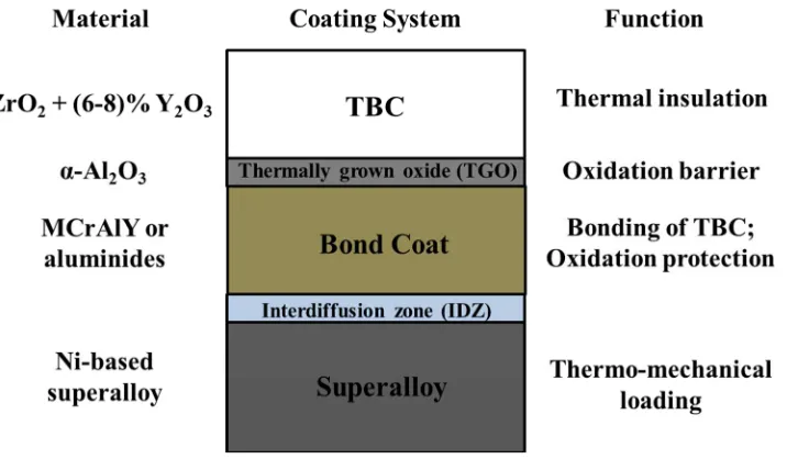
3-8). A typical TBC system that deposited onto the superalloy substrates is a multilayer coating
system which consists of a thermal insulating ceramic top coat, an aluminium-rich bond coat
between the top coat and the substrate as illustrated in Fig. 1. In addition, a thermally grown
oxide (TGO), predominantly alumina, forms at the interface between the top coat and the
bond coat during service at elevated temperatures and, meanwhile, an interdiffusion zone
(IDZ) develops at the bond coat/superalloy interface (Ref 9-13). In the past 30 years, work
concerned on increasing the durability of TBCs to resist mechanical and chemical
degradation has been reported extensively (Ref 14). It is widely recognised that the failure of
3
from the TGO growth and external thermal-mechanical strain (Ref 15-21). Hence,
maintaining the mechanical integrity of the multilayer TBC system is one of the major
challenges in the coating lifetime. Since the failure of TBCs is closely related to the yield,
ductility and creep characteristics of the bond coat, the mechanical behaviour of such
coatings are crucial to the durability of the overall system (Ref 22-24).
The mechanical characteristics of the bond coat largely depend on the coating microstructure,
in-service temperature as well as the coating thickness (Ref 25). Bond coats are typically
either of the diffusion aluminide type or the overlay MCrAlY type (M = Co and/or Ni), and
can comprise, for example, fcc -Ni, ordered ʹ (Ni3(Al, Ti) and bcc B2 β-(Ni, Co)Al phases
(Ref 26, 27). The amount of phases present in the bond coat, such as β, γʹ and σ phases, can
have a significant influence on the high temperature mechanical performance of TBCs (Ref
28, 29). The bcc β phase, commonly present in the bond coat alloys, is brittle at low
temperatures and exhibits increasing ductility above a critical temperature termed the
ductile-to-brittle transition temperature (DBTT) (Ref 30). Furthermore, the strain tolerance of the
coating is affected by the coating thickness since thin bond coats (typically ~200 µm thick in
TBCs) behaves quite differently from the monolithic alloys of the same chemistry at elevated
temperatures (Ref 31). It is therefore important to determine the mechanical characteristics of
the coatings with thicknesses close to TBC applications. However, previous studies mainly
focus on the oxidation behaviour and work concerned with the mechanical properties of the
bond coat alloys is very limited. Considering the importance of their mechanical
characteristics to the TBC system, it has been of considerable interest in accurately
determining the coating mechanical properties (Ref 32-34). The recently developed miniature
specimen tests appear to have the potential to provide such measurements (Ref 35, 36). The
use of miniature test techniques to provide mechanical properties of various specimen types
4
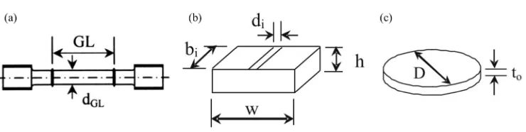
specimens can be conventional sub-size uniaxial specimen, impression test specimen and
small punch specimen, as shown in Fig. 2 (Ref 38). Among various miniature specimen test
methods, the small punch test (SPT) exhibits a particular interest in evaluating the mechanical
properties of thin coatings since the thickness of the specimen can be close to the coatings
(Ref 39). The small punch test method is based on the deformation of disc-shaped specimens
typically 8-10 mm in diameter and 0.25-0.5 mm in thickness at elevated temperatures to
obtain the elastic-plastic and creep properties. With the development of small punch testing
technique, clear interpretations of the deformation and failure mechanisms of bond coat
alloys can be achieved, though some divergent viewpoints are raised. In spite of the limited
mechanical property data collected on the bond coat alloys during the past few decades, a
review of this information has not yet been conducted. Therefore the aims of this paper are to
give an overview in mechanical property measurement using small punch test method, to
summarise and assess critically the literature on the mechanical properties of bond coat alloys
and to propose possible future exploitation of small punch test methods for mechanical
characterisation of coatings.
Since the compositions, spray techniques and sample sizes of the bond coats can exert a
profound influence on most mechanical properties, such information is reported when
applicable. The term “MCrAlY”, unless specified, will be used for ease of generic
discussions. Furthermore, different test methods where different sample sizes are required
could produce discrepancies in terms of material property data. Direct comparisons of such
data with different test methods are still under investigation. Thus material property data
should be considered with some caution due to the variations in test methods and sample
sizes. It is important to address that the main emphasis of this paper is to focus on the small
punch test method that can evaluate the mechanical and creep behaviour of coatings.
5
been reviewed previously (Ref 40-42), falls outside the scope although they are lightly
mentioned for qualitative evaluation of the coating properties.
2. Small punch test
Since the development of the small punch testing technique in early 1980s by Manahan et al.,
much attention has been paid to this unique test method where only a small volume of
material is required (Ref 43-45). The small punch test technique has been used for decades
now for mechanical characterisation of materials when analysing small regions of structural
components, such as creep resistant alloys, heat affected zones of welded joints and thin
coatings (Ref 46). The procedure of testing, the set-up of the test rig and the required test
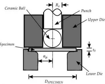
specimen dimensions are specified in the European Code of Practice (Ref 47). Fig. 3 shows a
schematic diagram of the small punch test rig (Ref 40). Generally, the test under bi-axial
stress state is carried out by applying a ceramic ball ended punch or a hemispherical punch to
one surface of the specimen which is firmly clamped between two circular dies. The
displacement of the disc specimen or the movement of the punch is used as the results for the
small punch test. There are two test configurations available: 1) under constant displacement
rate and 2) under constant load. The former is similar to a constant strain rate controlled
stress-strain test and is termed the displacement rate controlled small punch test, or more
simply, small punch tensile test. The latter has similarities to the standard uniaxial creep tests
under constant loads and is usually described as small punch creep test.
2.1 Small punch tensile test
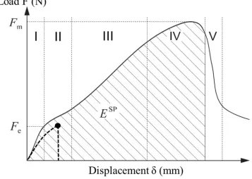
In the small punch tensile test (SPTT), the punch deforms the disc specimen at a given
constant displacement rate (typically 1 µm/s) and load versus displacement is measured, as
6
Zone I represents the initial elastic bending, followed by progressive extension of plastic
bending (II) in which the changing of the curve is caused by the yield stress of the specimen.
As the plastic bending deformation continues, a membrane behaviour is achieved due to the
balance of work hardening and stretching (III). After reaching the maximum load, the slope
starts to decrease due to material thinning, softening and damage (IV). In further deformation
of the specimen, localised necking and internal cracking are developed and macrocrack
initiates, resulting the punch penetration at the centre of the already cracked specimen (V).
For a brittle material, the specimen will fail at small displacements at the early stage of the
SPTT. This testing method has been predominately applied in investigating the mechanical
properties, especially the DBTT, of various materials (Ref 48-51).
The yield load, Fe, the maximum load, Fm, and small punch fracture energy, ESP, shown in
Fig. 4, are of interest for correlations with material properties. The yield load, Fe, indicating
the transition from elastic bending to plastic bending can be determined in many different
ways since the transition between zone I and II of the curve is usually not clear, which has
been detailed elsewhere (Ref 52-55). When plastic deformation occurs during the SPTT, it is
generally accepted that the yield stress (σy) can be approximated from the yield load (Fe)
divided by the square of the initial specimen thickness (t0). This can be expressed as (Ref
56-59):
𝜎
𝑦= 𝛼
1𝐹𝑒𝑡02
+ 𝛼
2 (1)where α1 and α2 are test constants depending on the dimensions of the test rig such as the punch diameter and the clamping distance. In the case of biaxial disc bending of a flat disc
fixed at its circumference, the initial elastic biaxial strain at the centre of the disc can be
approximated as (Ref 60, 61):
ε =
𝑡0𝛿7
where δ is the displacement of the specimen. The elastic modulus can then be obtained by
dividing the yield stress over the corresponding elastic biaxial strain. Similar to yield stress
obtained from SPTT, the ultimate tensile strength (σuts) is proposed to be related to the
maximum load, Fm, by the following equations, although some arguments still exist (Ref
62-64):
𝜎
𝑢𝑡𝑠= 𝛽
1 𝐹𝑚𝑡0𝛿𝑚
+ 𝛽
2 (3)𝜎
𝑢𝑡𝑠= 𝛽
1ʹ 𝐹𝑚𝑡02
+ 𝛽
2ʹ (4)where β1, β2, β1ʹ, β 2
ʹ are test constants and δ
m is the punch displacement at the maximum
load, Fm. Another important parameter that can be obtained is the small punch fracture energy,
ESP, calculated by integrating the area underneath the measured load-displacement curve as
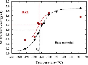
shown in Fig. 4. This can be utilised to estimate the ductile-to-brittle transition temperature of
a material. The small punch transition temperature is obtained from the temperature
dependence of ESP according to the Code of Practice (Ref 47), as shown in Fig. 5 (Ref 50).
The transition temperature in small punch test is found empirically proportional to that
obtained from conventional Charpy test (Ref 65). The small punch ductile-to-brittle transition
can also be characterised from the microscopic fractography which aligns with the distinctive
changes of shape in the small punch load-displacement curves. This will be detailed in a later
section to distinguish the onset of brittle and ductile behaviour.
2.2 Small punch creep test
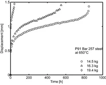
In the small punch creep test (SPCT), a constant load is employed and the displacement
versus time is analysed. This is widely used for creep analysis as it is similar to conventional
constant-load creep tests (Ref 66-70). Typical small punch creep test curves in the form of
8
large initial and primary deformation region followed by an approximately linear, secondary
region with a gradient, 𝛿̇𝑚𝑖𝑛, which is the minimum displacement rate. Finally, an
accelerating tertiary region leads to fracture. These curves show a similarity to typical
uniaxial creep curves which normally exhibit primary, secondary and tertiary creep regions.
However, it has been demonstrated that the SPCT curves are only superficially similar in
form to those typically seen in uniaxial tests (Ref 69). Considering the complex state of stress
and strain in the SPCT, throughout the literature, there have been several approximate
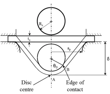
theoretical models addressing the stress and strain in the SPCT of which the set-up is shown
schematically in Fig. 7. Close investigation of finite element analysis revealed that there was
a zone related to “stiffening effects” of the deformed specimen, followed by “accelerating
effects” of necking and thinning near the edge of the contact (Ref 70-72). Based on the
Chakrabarty membrane stretch model, analytical expressions have been determined on the
ratio of the load to membrane stress, F/σ, and the maximum strain at the contact boundary
(Ref 73-75). Depending on the punch rig dimensions, for the case of ap = 2.0 mm and Rs =
1.25 mm, the F/σ and the strain for δ > 0.8 mm are given by:
F/σ = 1.72476δ − 0.05638𝛿
2− 0.17688𝛿
3 (5)ε = 0.17959δ + 0.09357𝛿
2+ 0.00440𝛿
3 (6)For the case of ap = 2.0 mm and Rs = 1.0 mm, the F/σ and the strain for δ > 0.8 mm can be
evaluated by:
F/σ = 1.56597δ − 0.18507𝛿
2− 0.14756𝛿
3 (7)ε = 0.20465δ + 0.12026𝛿
2+ 0.00950𝛿
3 (8)The relationship among the maximum F/σ, ap, Rs and t0 has been obtained from the CEN
code of practice when δ > 0.8 mm and this leads to an expression for σ (Ref 47):
𝜎 =
𝐹9
where Ksp is a non-dimensional correction factor to take account the localised necking during
large strain deformation. It is believed to be material dependent and is usually found between
1 and 1.3. By using the above equations, the displacement obtained from SPCT can be
converted to strain and the imposed stresses can be estimated. Other approaches are also
proposed in the literature (Ref 71, 76) but it has to be emphasised that due to the nature of
biaxial loading in small punch tests, the stress and strain characteristics are very complicated.
There is no universally accepted method for SPCT data interpretation available yet. Thus the
values calculated from the above equations in SPTT and SPCT may not be the exact stress
and strain experienced by the specimen, but only as the first approximation. Though with the
limitations of accurately estimating the stress and strain, the SPCT data is often characterised
by a minimum creep strain rate, 𝜀̇𝑚𝑖𝑛, which is converted from the minimum displacement
rate, and the total time to failure, tf, at different applied stress using the Norton power law at
constant temperatures (Eq. (10)),
𝜀̇
𝑚𝑖𝑛= 𝐵𝜎
𝑛(10)
and the rupture power law (Eq. (11)),
𝑡
𝑓=
1𝑀𝜎𝜒 (11)
The creep constants, n and χ, obtained from the above two equations are often used to
interpret the creep deformation and failure mechanism.
Overall, the advantage of using the SPTT and SPCT is that the material property data can be
obtained from a disc sample obtained directly by thermal spraying. Minor changes in
microstructural features, such as volume fraction of the precipitate phases, oxide inclusions
and un-melted particles, will in turn be expected to significantly affect the mechanical
properties. Although there is no universally accepted route for converting the SPT results to
equivalent uniaxial test data due to the complex loading and deformation behaviour, on-going
10
sensitivity of the bond coat microstructure to even small changes in thermal spray parameters
(Ref 4), the SPT can be employed as a cost-effective and fast-evaluating method to reckon
the coating performance at elevated temperatures. Previous work has demonstrated that the
SPT is able to generate reproducible and reliable comparative data on the mechanical
behaviour of bond coats prepared with different chemical compositions or by different
thermal spray processes. Since the SPTT is mainly used for DBTT evaluation and the SPCT
is used for creep assessment, hence the DBTT and creep behaviour of bond coats obtained
from bulk samples are reviewed below, in comparison to the recent advances in evaluating
such properties using the SPT.
3. Ductile-to-brittle transition
3.1. Testing of monolithic bond coat alloys
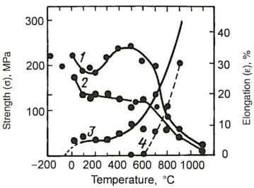
Since the DBTT of the bond coats depends on the bcc β-NiAl phase, the earliest DBTT work
on bond coat alloys dates back to the studies of bulk NiAl alloys. Tensile tests of strain to
cracking against temperature were used to determine the DBTT. The temperature dependent
mechanical properties of NiAl compound is shown in Fig. 8, which demonstrates the
approximate DBTT of NiAl compound at 600~800 °C according to the elongation
measurements (Ref 78). The temperature dependent ductility of thermally sprayed bond coats
can be obtained directly from the monolithic coating samples or from the deconvolution of
the coated systems. The DBTT for NiAl coatings are summarised in Table 1 (Ref 79-82). It is
noticed that the test methods, sample sizes and alloy compositions can significantly influence
the DBTT measurements. Considering the variety of bond coat alloys, it has been reported by
Meetham et al. that diffusional aluminides which are predominantly brittle phase exhibit
higher DBTT than those overlay MCrAlY coatings with brittle and ductile phase (Ref 83).
11
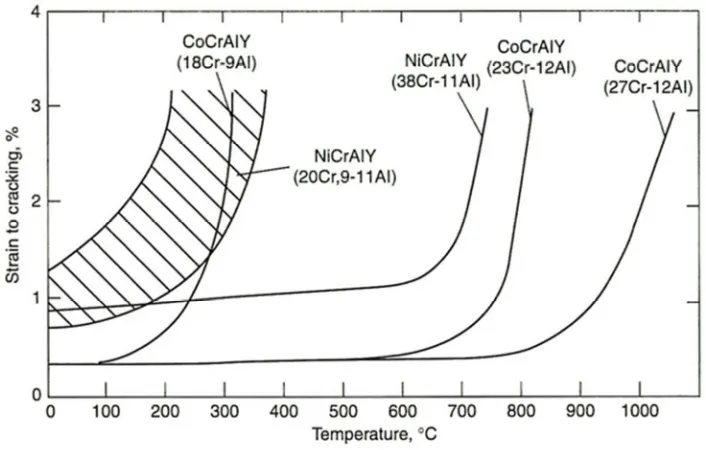
LPPS was around 700 C (Ref 84). It is understood that the amount of β phases in MCrAlY
varies with compositions and the Al content in the bond coat alloys dominates the
composition and volume fraction of the phase. The variations of strain to cracking of
several overlay MCrAlY alloys as a function of temperature are summarised in Fig. 9 (Ref 1),
revealing that the DBTT is largely dependent on the composition and microstructure of
MCrAlY coatings.
3.2. Results from SPTT
The above data are from the monolithic samples rather than thin coatings. It is known that the
coating thickness can have a profound effect on the strain tolerance and the defects in the
monolithic bond coat alloy samples can accelerate cracking. Thus to determine the DBTT,
the SPTT exhibits the unique advantages compared to the conventional bulk alloy testing in
terms of small sample size and accuracy for thermally sprayed coatings. The typical
load-displacement curves from SPTT at various temperatures for a CoNiCrAlY coating and a
nickel aluminide coating are shown in Fig. 10 (Ref 85, 86). It can be seen that the curves at
low temperatures (e.g. room temperature (RT), 400 C, 500 C) are predominately linear and
shows serrations prior to reaching the maximum load. The coating material exhibits little
plasticity and micro-cracking occurs at low temperatures during SPTT. The serrations seen in
Fig. 10(a) further support this view. At high temperatures, the curves are similar to the
schematic diagram in Fig. 4, exhibiting an increased plasticity with different deformation
regions due to the ductility of the material increases. It has been noticed that the DBTT
obtained from the SPTT decreases with smaller sample thickness for a given test apparatus
and sample diameter, due to the decreased strain tolerance of smaller thickness can result in
fast fracture without undergoing a complete elastic-plastic deformation region (Ref 64).
12
to reduced clearance between the deforming sample and the lower die, affecting the
deformation mechanism (Ref 87). Nevertheless, the SPTT has been validated as an effective
method for assessing the DBTT of bulk steels used in power plants (Ref 88, 89), irradiated
steels (Ref 90, 91) and, more recently, coatings (Ref 92, 93) when the sample geometry and
test apparatus are carefully controlled.
It is also shown that the SPTT can be an exciting mechanical testing method in determining
the temperature dependent mechanical properties of thin MCrAlY coatings, as shown in Fig.
11 (Ref 86), which shows good agreements with reported work (Ref 84). Kameda et al. have
used this method to study the local embrittlement effects and mechanical degradations of
MCrAlY coatings (Ref 94-96), showing the capability of SPTT in mechanical
characterisation and failure mechanism investigation of coatings. Eskner et al. have used this
technique to characterise the high temperature mechanical properties of plasma sprayed
MCrAlY coatings (Ref 93). Similar work has also been reported on other types of coatings,
demonstrating the capability of the SPTT in mechanical characterisation of thin coatings (Ref
92).
3.3. Fracture modes
The typical fracture patterns following SPTTs at RT, 500, 600 and 700 C for a CoNiCrAlY
bond coat are shown in Fig. 12 (Ref 86). There are four distinctly different fracture patterns,
namely cracking with little deformation at RT in Fig. 12(a), a five-star crack pattern at 500
C in Fig.12(b), a four star crack pattern at 600 C in Fig. 12(c), and peripheral cracking near
the centre of the specimen at 700 C in Fig. 12(d). The fracture behaviour at RT in Fig. 12(a)
exhibits the crack initiation at the centre of the disc and radial crack propagation with little
deflection of the sample. The fracture pattern observed at 500 C is evidence of a crack which
13
boundary, as highlighted by the circle in Fig. 12(b). Cracking can be observed at the
clamping boundary which shows little plastic deformation. At 600 C, the sample deformed
plastically to a conical shape and the four-star crack pattern was seen in Fig. 12(c). At 700 C,
the sample plastically deforms to the shape of a spherical cap and cracking occurs near the tip
in Fig. 12(d). Micrographs of the fracture surfaces are shown in Fig. 13 (Ref 85, 86). Flat
regions are evident in Fig. 13(a&b) and these distinctive concave features, approximately 30
µm across, show the evidence of brittle cleavage at low temperatures. Fracture surfaces at
high temperatures in Fig. 13(c&d) appear to have undergone extensive tearing with
intergranular cracking and ductile dimples. More recently, Chen et al. used a similar approach
of SPTT to investigate the DBTT of a similar CoNiCrAlY coating, showing the DBTT starts
to occur between 500 – 600 °C (Ref 97). The fracture surfaces exhibit the inter-splat fracture
at low temperatures and extensive ductile tearing at high temperatures, similar to the fracture
behaviour seen in Fig. 13. Despite the available data of DBTT for various diffusional
coatings and overlay MCrAlY coatings, the fracture modes vary with the composition,
microstructure, heat treatment history, as well as deposition methods (Ref 98, 99). Since the
β-NiAl phase is the dominant phase in MCrAlY coatings, the fracture mechanisms are very
likely to be related to the size and distribution of the β-NiAl phase. It is found that the
fracture behaviour of a CoNiCrAlY coating with a 30 vol% β phase exhibits a mixture of
ductile tearing and brittle cleavage at low temperatures due to the presence of the ductile
matrix phase (Ref 97). Similar findings were also reported on a NiCoCrAlY coating with a
similar β phase content, showing the matrix tearing and inter-splat fracture at low
temperatures (Ref 93). Whereas the nickel aluminide coating with predominant β phase
shows the brittle cleavage more obviously at low temperatures (Ref 85). It is proposed from
these reported studies that the MCrAlY coating exhibits a mixed mode of transgranular and
14
temperatures above DBTT. Nevertheless, it can be found that the DBTT from the SPTT
agrees well with the previously reported data in Fig. 9. Therefore, the SPTT can be regarded
as one of the cost-effective and promising testing methods for mechanical characterisation of
bond coats, though some arguments still exist in terms of the accuracy and interpretation of
the test results.
4. Creep behaviour
4.1. Reported creep studies on MCrAlY bond coat alloys
Data on creep properties of free-standing bond coats are somewhat scarce in the literature
(Ref 100-103). The available studies on creep of monolithic MCrAlY-type samples are
summarised in Table 2. Hebsur et al. carried out creep tests on 9 mm thick NiCoCrAlY
(PWA-276) alloys prepared by plasma spraying, in which it was reported that dislocation
climb or viscous flow creep mechanism occurred between 660~850 °C and grain boundary
diffusional creep mechanism became dominant from 850 to 1050 °C (Ref 104, 105). Stress
relaxation experiments were carried out by Wereszczak et al. (Ref 106) using bulk MCrAlY
alloys prepared by hot isostatic pressing of gas atomised powders to determine creep
parameters. Furthermore, a series of stress relaxation tests on various MCrAlY coatings were
carried out by Brindley and Whittenberger (Ref 107) to determine the stress exponent.
Thompson and co-workers (Ref 108) used the vacuum plasma spraying method to make
1.4 mm thick samples of NiCrAlY and CoNiCrAlY alloys for creep testing of miniature
tensile samples at 750 and 850 C. Ajdelsztajn et al. examined the effects of fine precipitates
on the creep deformation mechanism of NiCrAlY (wt.%) bulk rectangular bars produced by
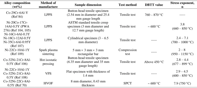
spark plasma sintering (Ref 109). Among the limited number of creep studies in Table 2, it
can be seen that the stress exponents obtained over a broad temperature regime are between
15
accurately measure the creep properties of thin coatings, Taylor et al. proposed a method for
evaluating the creep properties of as-deposited MCrAlY coatings by using a coated tensile
specimen, in which the overall strain/time response had to be deconvoluted to obtain the
creep characteristics of the coating (Ref 110). They claimed that thin coatings behaved
differently from monolithic alloys of the same chemistry and the delamination between the
coating and substrate needed to be carefully controlled.
Since the application of SPCT has been extended from heat-affected zones of weldments and
creep-resistant alloys to thin coatings (Ref 46), Chen et al. used the SPCT to investigate the
creep behaviour of a thin CoNiCrAlY coating with thickness ~0.5 mm (Ref 70). The
displacement versus time curve from SPCT is shown in Fig. 14. The overall shape of the
SPCT curves looks superficially similar to conventional uniaxial creep curves, exhibiting an
instantaneous large deformation region, followed by a steady secondary region and an
accelerating tertiary region leading to fracture. Similarly, the SPCT curves also changes when
increasing the applied load, where a reduction in the primary and secondary stages is resulted
and fast fracture occurs. The comparison of the creep properties in Table 2 suggests the stress
exponent, n, in the Norton power law equation for a CoNiCrAlY coating alloy is in the range
of 3-5 from the conventional tests, while the stress exponent derived from SPCT is 7.9. For
the power law (dislocation) creep, the stress exponent usually varies from 3 to 10 at lower
temperature region of the MCrAlY alloys (Ref 104). The SPCT result is consistent with the
mechanism proposed for this CoNiCrAlY coating alloy at 750 C, demonstrating its
capability in assessing the creep properties of MCrAlY alloys in the form of thin coatings.
4.2. SPCT fracture surface evaluation
During the SPCT, the punch progressively penetrates the disc specimen at intermediate loads
16
that the initial cone region is developed due to the large plastic deformation in the primary
region. When initially loaded, the contact area between the spherical punch and the flat disc
specimen is essentially a point. Thus localised stresses at the point of contact are very high,
which may well exceed the yield stress of the material, leading to an initial large deformation
of the specimen. The cone region continues to grow as the punch moves further under
constant load, during which the contact area between the punch and specimen increases. The
steady secondary region is achieved by a balance of “stiffening effects” of the specimen due
to the geometric shape changes and the “softening effects” due to the formation of voids and
microcracks. The failure point is usually near the edge of contact between the punch and
specimen, where localised necking and thinning have occurred. Fig. 16 shows typical
secondary electron images of the fracture surface when failure occurs at the edge of contact.
The cone-shaped nature shown in Fig. 16(a) further supports this view. Since it has been
shown that the CoNiCrAlY coating undergoes a brittle to ductile transition between 500 –
700 C, the extensive creep deformation at 750 C is consistent with the evidence of matrix
tearing seen in Fig. 16(b) and (c). It appears that the majority of the surface consists of
intergranular failure. Besides, different thermal spray techniques are believed to have
profound effects on the test results, owing to the variations in the microstructure of MCrAlY
coatings. The defects in the HVOF coatings, such as the oxide inclusions, can influence the
creep life of the coating (Ref 70). Such oxide inclusions may act as crack initiation sites
which accelerate the voids nucleation and crack propagation. It was further reported that the
vacuum plasma sprayed CoNiCrAlY coatings exhibited faster creep fracture compared to the
HVOF coatings due to the presence of un-melted particles in the VPS coating (Ref 111). The
un-melted particles produce large mechanical discrepancies in the coating and the cracking is
17
Such defects resulted from the thermal spraying processes can cause detrimental effects to the
coating creep life.
4.3. Failure mechanism investigation during SPCT
Cross-section of the coating specimen which underwent creep deformation for 1000 h at 750
C in SPCT but prior to failure is shown in Fig. 17(a). Material thinning and macroscopic
cavities are found in region B. This is the area where the creep rupture is observed to be
occurring during SPCT at approximately the edge of contact. Microstructure in the clamped
region, A, is found to be essentially unchanged, as shown in Fig. 17(b). The grey contrast
features between region A and B are found to be full of cavities which are covered by internal
oxides during the testing in air at 750 C. Linkage of these cavities is seen in Fig. 17(c) due to
the “stretching effects” occurred in this region. In Fig. 17(d) it is evident that local voids,
cavities and cracks appear to have grown and propagated together to form a network of
macroscopic cracks, leading to the final failure of the coating specimen. Fig. 18 shows an
EBSD-derived inverse pole figure and the corresponding phase map of an area taken from
region B shown in Fig. 17. It is shown that the creep cavitation voids nucleate at /β
interphase boundaries as well as at / grain boundaries, with the void linkage leading to final
failure of the coating. This agrees well with the characteristics of intergranular failure seen in
Fig. 16. The stress exponent determined from SPCT (nSP = 7.9) is consistent with the creep
failure mechanism proposed by Hebsur and Miner (Ref 104, 105), suggesting that power law
(dislocation) creep is the governing mechanism at lower temperature in these MCrAlY alloys.
Furthermore, similar to the DBTT, it is believed that the composition and microstructure
would affect the creep behaviour of MCrAlY coatings, especially when the β phase content
changes. It has been reported that the MCrAlY alloys exhibited superplastic behaviour at very
18
MCrAlY compositions can alter the onset of the superplastic behaviour and dominate the
creep mechanism in MCrAlY coatings. However, such studies on the creep mechanism of
MCrAY coatings with different β phase content have not been reported yet.
Considering the complicated stress-strain behaviour of the bi-axial loading in SPCT at
elevated temperatures, numerical modelling work is on-going to correlate the creep properties
with the conventional uniaxial tensile creep test. Even so, the SPCT can be a reliable tool to
rank different types of coatings given that the test configurations are carefully monitored.
Since the creep behaviour of the bond coat is very important to the durability of TBC systems,
there are clearly considerable needs to determine creep properties of bond coats which are
prepared by thermal spraying processes such as HVOF or LPPS and which have thicknesses
as close as possible to those used in industrial TBC systems. Although it is clear that further
work is necessary when using SPCT to determine the power law parameters for specific bond
coat alloys, it is evident that the SPCT is a valuable tool to evaluate the creep behaviour of
thin coatings.
5. Summary
This overview is focused on the DBTT and creep properties of MCrAlY bond coats, with
particular emphasis placed on the application of small punch testing to investigate such
properties. Though the interpretation of the results obtained from small punch testing is
strongly user driven, this miniaturised testing technique can act as a useful tool to evaluate
the coating performance with coating thickness close to the industrial applications. At present,
a primary area of interest is validating and demonstrating the deformation mechanisms in the
small punch test and correlating the stress and strain with uniaxial testing. Indeed, data from
this aspect are specifically excluded but have been reviewed elsewhere. Nevertheless, it is
19
properties can be obtained from small punch test results. Fast evaluation of the coatings using
small punch testing will enable more reliable and flexible developments of existing coatings
and new coatings. Small punch tests are being developed to allow reasonable assessment of
coating properties including yield, creep as well as fatigue (Ref 112-114). Such tests can be
applied in the multi-layer coating systems to investigate the role of different layers. With the
aid of small punch tests, there are areas where additional work can be conducted for the
future to mechanically characterise thermally sprayed coatings and these are typified as:
(i) Standardisation of the small punch test details for coatings to ensure the
reproducibility and accuracy.
(ii) Correlation with the uniaxial stress and strain to allow more sound interpretation
of small punch test results for coatings.
(iii) Optimisation on the microstructure characteristics, mechanical properties and
manufacturing parameters of thermally sprayed coatings.
(iv) Investigation of the interaction of different layers in the multi-layer TBC systems
such as the TGO, bond coat, interdiffusion zone and substrate.
Acknowledgements
The authors would like to thank Mr. Shane Maskill for his skilled assistance in carrying out
the small punch testing experiments at the University of Nottingham. The authors also thank
Prof. Graham McCartney, Prof. Thomas Hyde and Prof. John Nicholls for helpful discussions.
We would also like to thank Loughborough University and Dr. G. West for assistance with
the EBSD study. The financial support from Zhejiang Natural Science Foundation
Programme (No. LQ16E060001), Zhejiang Commonweal Technology Project (No.
2016C31023), Ningbo Enrich People Project (2016C10035) and Ningbo Natural Science
20 References
1. S. Bose, High Temperature Coatings, Elsevier Butterworth-Heinemann, 2007
2. C.U. Hardwicke, and Y.-C. Lau, Advances in Thermal Spray Coatings for Gas Turbines and Energy Generation: A Review, J. Therm. Spray Technol., 2013, 22(5), p. 564-576
3. N. Curry, N. Markocsan, X.-H. Li, A. Tricoire, and M. Dorfman, Next Generation Thermal Barrier Coatings for the Gas Turbine Industry, J. Therm. Spray Technol., 2011, 20(1), p. 108-115
4. A. Feuerstein, J. Knapp, T. Taylor, A. Ashary, A. Bolcavage, and N. Hitchman, Technical and Economical Aspects of Current Thermal Barrier Coating Systems for Gas Turbine Engines by Thermal Spray and EBPVD: A Review, J. Therm. Spray Technol., 2008, 17(2), p. 199-213
5. U. Schulz, C. Leyens, K. Fritscher, M. Peters, B. Saruhan-Brings, O. Lavigne, J.M. Dorvaux, M. Poulain, R. Mevrel, and M.L. Caliez, Some recent trends in research and technology of advanced thermal barrier coatings, Aerosp. Sci. Technol., 2003, 7(1), p. 73-80
6. A.G. Evans, D.R. Mumm, J.W. Hutchinson, G.H. Meier, and F.S. Pettit, Mechanisms controlling the durability of thermal barrier coatings, Prog. Mater. Sci., 2001, 46(5), p. 505-553
7. B.A. Pint, I.G. Wright, and W.J. Brindley, Evaluation of thermal barrier coating systems on novel substrates, J. Therm. Spray Technol., 2000, 9(2), p. 198-203
8. M. Gupta, K. Skogsberg, and P. Nylén, Influence of Topcoat-Bondcoat Interface Roughness on Stresses and Lifetime in Thermal Barrier Coatings, J. Therm. Spray Technol., 2014, 23(1), p. 170-181
9. H. Chen, G.A. Jackson, K.T. Voisey, and D.G. McCartney, Modelling and experimental study on β-phase depletion behaviour of HVOF sprayed free-standing CoNiCrAlY coatings during oxidation, Surf. Coat. Technol., 2016, 291, p. 34-42 10. H. Chen, D.G. McCartney, and K.T. Voisey, Effect of surface conditions on internal
oxidation and nitridation of HVOF MCrAlY coatings, Mater. High Temp., 2015,
32(1-2), p. 215-220
11. W.R. Chen, Degradation of a TBC with HVOF-CoNiCrAlY Bond Coat, J. Therm. Spray Technol., 2014, 23(5), p. 876-884
12. Y. Bai, C. Ding, H. Li, Z. Han, B. Ding, T. Wang, and L. Yu, Isothermal Oxidation Behavior of Supersonic Atmospheric Plasma-Sprayed Thermal Barrier Coating System, J. Therm. Spray Technol., 2013, 22(7), p. 1201-1209
13. R.D. Jackson, M.P. Taylor, H.E. Evans, and X.-H. Li, Oxidation study of an EB-PVD MCrAlY thermal barrier coating system, Oxid. Met., 2011, 76(3-4), p. 259-271
14. A. Vardelle, C. Moreau, J. Akedo, H. Ashrafizadeh, C.C. Berndt, J.O. Berghaus, M. Boulos, J. Brogan, A.C. Bourtsalas, A. Dolatabadi, M. Dorfman, T.J. Eden, P. Fauchais, G. Fisher, F. Gaertner, M. Gindrat, R. Henne, M. Hyland, E. Irissou, E.H. Jordan, K.A. Khor, A. Killinger, Y.-C. Lau, C.-J. Li, L. Li, J. Longtin, N. Markocsan, P.J. Masset, J. Matejicek, G. Mauer, A. McDonald, J. Mostaghimi, S. Sampath, G. Schiller, K. Shinoda, M.F. Smith, A.A. Syed, N.J. Themelis, F.-L. Toma, J.P. Trelles, R. Vassen, and P. Vuoristo, The 2016 Thermal Spray Roadmap, J. Therm. Spray Technol., 2016, 25(8), p. 1376-1440
21
16. R. Darolia, Thermal barrier coatings technology: critical review, progress update, remaining challenges and prospects, Int. Mater. Rev., 2013, 58(6), p. 315-348
17. L.Y. Ni, C. Liu, H. Huang, and C.G. Zhou, Thermal Cycling Behavior of Thermal Barrier Coatings with HVOF NiCrAlY Bond Coat, J. Therm. Spray Technol., 2011,
20(5), p. 1133-1138
18. D. Naumenko, V. Shemet, L. Singheiser, and W. Quadakkers, Failure mechanisms of thermal barrier coatings on MCrAlY-type bondcoats associated with the formation of the thermally grown oxide, J. Mater. Sci., 2009, 44(7), p. 1687-1703
19. J. Toscano, D. Naumenko, A. Gil, L. Singheiser, and W.J. Quadakkers, Parameters affecting TGO growth rate and the lifetime of TBC systems with MCrAlY-bondcoats, Mater. Corros., 2008, 59(6), p. 501-507
20. C. Mercer, S. Faulhaber, N. Yao, K. McIlwrath, and O. Fabrichnaya, Investigation of the chemical composition of the thermally grown oxide layer in thermal barrier systems with NiCoCrAlY bond coats, Surf. Coat. Technol., 2006, 201(3-4), p. 1495-1502
21. A. Gil, V. Shemet, R. Vassen, M. Subanovic, J. Toscano, D. Naumenko, L. Singheiser, and W.J. Quadakkers, Effect of surface condition on the oxidation behaviour of MCrAlY coatings, Surf. Coat. Technol., 2006, 201(7), p. 3824-3828
22. X. Gong, Y. Yang, Y. Ma, H. Peng, and H. Guo, Microstructures and mechanical properties of β-NiAlHf coated single crystal superalloy, Mater. Sci. Eng. A, 2016, 673, p. 39-46
23. U. Hermosilla, M.S.A. Karunaratne, I.A. Jones, T.H. Hyde, and R.C. Thomson, Modelling the high temperature behaviour of TBCs using sequentially coupled microstructural–mechanical FE analyses, Mater. Sci. Eng. A, 2009, 513–514, p. 302-310
24. K.J. Hemker, B.G. Mendis, and C. Eberl, Characterizing the microstructure and mechanical behavior of a two-phase NiCoCrAlY bond coat for thermal barrier systems, Mater. Sci. Eng. A, 2008, 483–484, p. 727-730
25. A. Scrivani, U. Bardi, L. Carrafiello, A. Lavacchi, F. Niccolai, and G. Rizzi, A comparative study of high velocity oxygen fuel, vacuum plasma spray, and axial plasma spray for the deposition of CoNiCrAlY bond coat alloy, J. Therm. Spray Technol., 2003, 12(4), p. 504-507
26. J.R. Nicholls, Designing oxidation-resistant coatings, JOM, 2000, 52(1), p. 28-35 27. H. Chen, and D.G. McCartney, Some aspects on modelling of the β-phase depletion
behaviour under different oxide growth kinetics in HVOF CoNiCrAlY coatings, Surf. Coat. Technol., 2017, 313, p. 107-114
28. J. Toscano, A. Gil, T. Hüttel, E. Wessel, D. Naumenko, L. Singheiser, and W. Quadakkers, Temperature dependence of phase relationships in different types of MCrAlY-coatings, Surf. Coat. Technol., 2007, 202(4), p. 603-607
29. H. Chen, Y.Q. Si, and D.G. McCartney, An analytical approach to the β-phase coarsening behaviour in a thermally sprayed CoNiCrAlY bond coat alloy, J. Alloys Compd., 2017, 704, p. 359-365
30. R.D. Noebe, R.R. Bowman, and M.V. Nathal, Physical and mechanical properties of the B2 compound NiAl, Int. Mater. Rev., 1993, 38(4), p. 193-232
31. M.P. Taylor, H.E. Evans, E.P. Busso, and Z.Q. Qian, Creep properties of a Pt-aluminide coating, Acta Mater., 2006, 54(12), p. 3241-3252
22
33. H. Waki, A. Oikawa, M. Kato, S. Takahashi, Y. Kojima, and F. Ono, Evaluation of the Accuracy of Young’s Moduli of Thermal Barrier Coatings Determined on the Basis of Composite Beam Theory, J. Therm. Spray Technol., 2014, 23(8), p. 1291-1301
34. L. Wang, J.X. Ni, F. Shao, J.S. Yang, X.H. Zhong, H.Y. Zhao, C.G. Liu, S.Y. Tao, Y. Wang, and D.Y. Li, Failure Behavior of Plasma-Sprayed Yttria-Stabilized Zirconia Thermal Barrier Coatings Under Three-Point Bending Test via Acoustic Emission Technique, J. Therm. Spray Technol., 2017, 26(1), p. 116-131
35. R. Musalek, O. Kovarik, J. Medricky, N. Curry, S. Bjorklund, and P. Nylen, Fatigue Testing of TBC on Structural Steel by Cyclic Bending, J. Therm. Spray Technol., 2015, 24(1), p. 168-174
36. H. Waki, K. Takizawa, M. Kato, and S. Takahashi, Accuracy of Young’s Modulus of Thermal Barrier Coating Layer Determined by Bending Resonance of a Multilayered Specimen, J. Therm. Spray Technol., 2016, 25(4), p. 684-693
37. T.H. Hyde, W. Sun, and J.A. Williams, Requirements for and use of miniature test specimens to provide mechanical and creep properties of materials: a review, Int. Mater. Rev., 2007, 52(4), p. 213-255
38. T. Hyde, and W. Sun, A novel, high-sensitivity, small specimen creep test, J. Strain Anal. Eng. Des., 2009, 44(3), p. 171-185
39. G.E. Lucas, Review of small specimen test techniques for irradiation testing, MTA, 1990, 21(5), p. 1105-1119
40. J.P. Rouse, F. Cortellino, W. Sun, T.H. Hyde, and J. Shingledecker, Small punch creep testing: review on modelling and data interpretation, Mater. Sci. Technol., 2013,
29, p. 1328-1345
41. M. Bruchhausen, S. Holmström, I. Simonovski, T. Austin, J.M. Lapetite, S. Ripplinger, and F. de Haan, Recent developments in small punch testing: Tensile properties and DBTT, Theor. Appl. Fract. Mech., 2016, 86A, p. 2-10
42. P. Dymáček, Recent developments in small punch testing: Applications at elevated temperatures, Theor. Appl. Fract. Mech., 2016, 86A, p. 25-33
43. M.P. Manahan, A new postirradiation mechanical behavior test-the miniaturized disk bend test, Nucl. Technol., 1983, 63(2), p. 295-315
44. M.P. Manahan, A.S. Argon, and O.K. Harling, The development of a miniaturized disk bend test for the determination of postirradiation mechanical-properties, J. Nucl. Mater., 1982, 103(1-3), p. 1545-1550
45. X. Mao, T. Shoji, and H. Takahashi, Characterization of fracture behaviour in small punch test by combined recrystallization-etch method and rigid plastic analysis, J. Test. Eval., 1987, 15(1), p. 30-37
46. R.C. Hurst, and K. Matocha, A Renaissance in the Use of the Small Punch Testing Technique, In ASME Pressure Vessels and Piping Conference, American Society of Mechanical Engineers, 2015, p. PVP2015-45095
47. CEN Workshop Agreement. CWA 15627:2006 E, "Small punch test method for metallic materials," CEN, European Committee for Standardization, Brussels Belgium, 2006
48. S. Rasche, and M. Kuna, Improved small punch testing and parameter identification of ductile to brittle materials, Int. J. Pressure Vessels Piping, 2015, 125, p. 23-34 49. T. Linse, M. Kuna, and H.W. Viehrig, Quantification of brittle-ductile failure
23
50. K. Turba, R. Hurst, and P. Hähner, Evaluation of the ductile–brittle transition temperature in the NESC-I material using small punch testing, Int. J. Pressure Vessels Piping, 2013, 111–112, p. 155-161
51. S. Dryepondt, and B.A. Pint, Determination of the ductile to brittle temperature transition of aluminide coatings and its influence on the mechanical behavior of coated specimens, Surf. Coat. Technol., 2010, 205(5), p. 1195-1199
52. X. Mao, and H. Takahashi, Development of a further-miniaturized specimen of 3 mm diameter for tem disk (ø 3 mm) small punch tests, J. Nucl. Mater., 1987, 150(1), p. 42-52
53. C. Rodríguez, J. García, E. Cárdenas, and C. Betegón, Mechanical properties characterization of heat-affected zone using the small punch test, Weld. J., 2010,
88(9), p. 188-192
54. K. Guan, L. Hua, Q. Wang, X. Zou, and M. Song, Assessment of toughness in long term service CrMo low alloy steel by fracture toughness and small punch test, Nucl. Eng. Des., 2011, 241(5), p. 1407-1413
55. M.A. Contreras, C. RodrÍGuez, F.J. Belzunce, and C. Betegón, Use of the small punch test to determine the ductile-to-brittle transition temperature of structural steels, Fatigue Fract. Eng. Mater. Struct., 2008, 31(9), p. 727-737
56. T.E. García, C. Rodríguez, F.J. Belzunce, and C. Suárez, Estimation of the mechanical properties of metallic materials by means of the small punch test, J. Alloys Compd., 2014, 582, p. 708-717
57. C. Rodríguez, E. Cárdenas, F.J. Belzunce, and C. Betegón, Fracture Characterization of Steels by Means of the Small Punch Test, Exp. Mech., 2013, 53(3), p. 385-392 58. S. Haroush, E. Priel, D. Moreno, A. Busiba, I. Silverman, A. Turgeman, R. Shneck,
and Y. Gelbstein, Evaluation of the mechanical properties of SS-316L thin foils by small punch testing and finite element analysis, Mater. Des., 2015, 83, p. 75-84 59. K. Matocha, Small-punch testing for tensile and fracture behavior: experiences and
way forward, ASTM Special Tech. Publ. STP,, 2015, 1576, p. 145-159
60. J.S. Cheon, and I.S. Kim, Initial deformation during small punch testing., J. Test. Eval., 1996, 24(4), p. 255-262
61. F.M. Huang, and M.L. Hamilton, Bend testing for miniature disks, Nucl. Technol., 1982, 57(2), p. 234-242
62. E. Fleury, and J.S. Ha, Small punch tests to estimate the mechanical properties of steels for steam power plant: I. Mechanical strength, Int. J. Pressure Vessels Piping, 1998, 75(9), p. 699-706
63. Y. Ruan, P. Spätig, and M. Victoria, Assessment of mechanical properties of the martensitic steel EUROFER97 by means of punch tests, J. Nucl. Mater., 2002, 307– 311, Part 1, p. 236-239
64. E. Altstadt, H.E. Ge, V. Kuksenko, M. Serrano, M. Houska, M. Lasan, M. Bruchhausen, J.M. Lapetite, and Y. Dai, Critical evaluation of the small punch test as a screening procedure for mechanical properties, J. Nucl. Mater., 2016, 472, p. 186-195
65. M.-C. Kim, Y.J. Oh, and B.S. Lee, Evaluation of ductile–brittle transition temperature before and after neutron irradiation for RPV steels using small punch tests, Nucl. Eng. Des., 2005, 235(17–19), p. 1799-1805
24
67. S. Komazaki, T. Kato, Y. Kohno, and H. Tanigawa, Creep property measurements of welded joint of reduced-activation ferritic steel by the small-punch creep test, Mater. Sci. Eng. A, 2009, 510–511, p. 229-233
68. D.T. Blagoeva, and R.C. Hurst, Application of the CEN (European Committee for Standardization) small punch creep testing code of practice to a representative repair welded P91 pipe, Mater. Sci. Eng. A, 2009, 510-511, p. 219-223
69. T.H. Hyde, M. Stoyanov, W. Sun, and C.J. Hyde, On the interpretation of results from small punch creep tests, J. Strain Anal. Eng. Des., 2010, 45(3), p. 141-164
70. H. Chen, T.H. Hyde, K.T. Voisey, and D.G. McCartney, Application of small punch creep testing to a thermally sprayed CoNiCrAlY bond coat, Mater. Sci. Eng. A, 2013,
585, p. 205-213
71. Z. Yang, and Z. Wang, Relationship between strain and central deflection in small punch creep specimens, Int. J. Pressure Vessels Piping, 2003, 80(6), p. 397-404 72. T.H. Hyde, and W. Sun, Some considerations on specimen types for small sample
creep tests, Mater. High Temp., 2010, 27(3), p. 157-165
73. R. Sturm, and Y. Li, Small-punch testing of a weld’s heat-affected zones, Materiali in Technologije, 2006, 40(2), p. 49-54
74. Y. Li, and R. Sturm, Determination of Creep Properties From Small Punch Test, Proc. ASME Pressure Vessels & Piping Division Conference, 2008, p. 739-750
75. J. Chakrabarty, A theory of stretch forming over hemispherical punch heads, Int. J. Mech. Sci, 1970, 12(4), p. 315-325
76. X. Mao, M. Saito, and H. Takahashi, Small punch test to predict ductile fracture toughness JIC and brittle fracture toughness KIC, Scr Metall Mater, 1991, 25(11), p. 2481-2485
77. M. Evans, and D. Wang, The small punch creep test: some results from a numerical model, J. Mater. Sci., 2008, 43(6), p. 1825-1835
78. Y. Tamarin, Protective coatings for turbine blades, Asm Intl, 2002
79. R.R. Bowman, R.D. Noebe, S.V. Raj, and I.E. Locci, Correlation of deformation mechanisms with the tensile and compressive behavior of NiAl and NiAl(Zr) intermetallic alloys, MTA, 1992, 23(5), p. 1493-1508
80. M. Arana Antelo, P.K. Johnson, K.M. Ostolaza, and J. Bressers, Analysis of the fracture behaviour of an aluminide coating on a single-crystal superalloy under tensile conditions, Mater. Sci. Eng. A, 1998, 247(1–2), p. 40-50
81. P. Hancock, H.H. Chien, J.R. Nicholls, and D.J. Stephenson, In situ measurements of the mechanical properties of aluminide coatings, Surf. Coat. Technol., 1990, 43, p. 359-370
82. T.C. Totemeier, W.F. Gale, and J.E. King, Fracture behaviour of an aluminide coating on a single crystal nickel base superalloy, Mater. Sci. Eng. A, 1993, 169(1), p. 19-26 83. G.W. Meetham, Use of protective coatings in aero gas turbine engines, Mater. Sci.
Technol., 1986, 2(3), p. 290-294
84. R.W. Smith, Mechanical properties of a low-pressure-plasma-applied Co-Cr-Al-Y coating, Thin Solid Films, 1981, 84(1), p. 59-72
85. M. Eskner, and R. Sandström, Measurement of the ductile-to-brittle transition temperature in a nickel aluminide coating by a miniaturised disc bending test technique, Surf. Coat. Technol., 2003, 165(1), p. 71-80
25
87. B. Ule, R. Sturm, and V. Leskovsek, Effects of test specimen geometry in creep behaviour of 12Cr steel in miniaturised disc bend tests, Mater. Sci. Technol., 2003,
19(12), p. 1771-1776
88. F. Dobeš, and K. Milička, Estimation of ductility of Fe–Al alloys by means of small punch test, Intermetallics, 2010, 18(7), p. 1357-1359
89. J.H. Bulloch, A review of the ESB small punch test data on various plant components with special emphasis on fractographic details, Eng. Failure Anal., 2002, 9(5), p. 511-534
90. M.C. Kim, Y.J. Oh, and B.S. Lee, Evaluation of ductile-brittle transition temperature before and after neutron irradiation for RPV steels using small punch tests, Nucl. Eng. Des., 2005, 235(17-19), p. 1799-1805
91. Z.X. Wang, H.J. Shi, J. Lu, P. Shi, and X.F. Ma, Small punch testing for assessing the fracture properties of the reactor vessel steel with different thicknesses, Nucl. Eng. Des., 2008, 238(12), p. 3186-3193
92. S. Soltysiak, M. Selent, S. Roth, M. Abendroth, M. Hoffmann, H. Biermann, and M. Kuna, High-temperature small punch test for mechanical characterization of a nickel-base super alloy, Mater. Sci. Eng. A, 2014, 613, p. 259-263
93. M. Eskner, and R. Sandström, Mechanical properties and temperature dependence of an air plasma-sprayed NiCoCrAlY bondcoat, Surf. Coat. Technol., 2006, 200(8), p. 2695-2703
94. J. Kameda, T.E. Bloomer, Y. Sugita, A. Ito, and S. Sakurai, High temperature environmental attack and mechanical degradation of coatings in gas turbine blades, Mater. Sci. Eng. A, 1997, 229(1-2), p. 42-54
95. J. Kameda, T.E. Bloomer, Y. Sugita, A. Ito, and S. Sakurai, Mechanical properties of aluminized CoCrAlY coatings in advanced gas turbine blades, Mater. Sci. Eng. A, 1997, 234-236, p. 489-492
96. J. Kameda, T. Bloomer, and S. Sakurai, Oxidation/carbonization/nitridation and in-service mechanical property degradation of CoCrAlY coatings in land-based gas turbine blades, J. Therm. Spray Technol., 1999, 8(3), p. 440-446
97. H. Chen, and T.H. Hyde, Use of multi-step loading small punch test to investigate the ductile-to-brittle transition behaviour of a thermally sprayed CoNiCrAlY coating, Mater. Sci. Eng. A, 2017, 680, p. 203-209
98. M.H. Enayati, F. Karimzadeh, M. Tavoosi, B. Movahedi, and A. Tahvilian, Nanocrystalline NiAl Coating Prepared by HVOF Thermal Spraying, J. Therm. Spray Technol., 2011, 20(3), p. 440-446
99. J.Z. Chen, H. Herman, and S. Safai, Evaluation of NiAl and NiAl-B deposited by vacuum plasma spray, J. Therm. Spray Technol., 1993, 2(4), p. 357-361
100. M. Ahrens, R. Vaßen, D. Stöver, and S. Lampenscherf, Sintering and creep processes in plasma-sprayed thermal barrier coatings, J. Therm. Spray Technol., 2004, 13(3), p. 432-442
101. R. Soltani, T.W. Coyle, and J. Mostaghimi, Microstructure and Creep Behavior of Plasma-Sprayed Yttria Stabilized Zirconia Thermal Barrier Coatings, J. Therm. Spray Technol., 2008, 17(2), p. 244-253
102. R. Soltani, E. Garcia, T.W. Coyle, J. Mostaghimi, R.S. Lima, B.R. Marple, and C. Moreau, Thermomechanical behavior of nanostructured plasma sprayed zirconia coatings, J. Therm. Spray Technol., 2006, 15(4), p. 657-662
26
104. M.G. Hebsur, and R.V. Miner, High temperature tensile and creep behaviour of low pressure plasma-sprayed Ni-Co-Cr-Al-Y coating alloy, Mat. Sci. Eng., 1986, 83(2), p. 239-245
105. M.G. Hebsur, and R.V. Miner, Stress rupture and creep behavior of a low pressure plasma-sprayed NiCoCrAlY coating alloy in air and vacuum, Thin Solid Films, 1987,
147(2), p. 143-152
106. A.A. Wereszczak, J.G. Hemrick, T.P. Kirkland, J.A. Haynes, T.J. Fitzgerald, and J.E. Junkin, Stress relaxation of MCrAlY bond coat alloys as a function of temperature and strain, Proceedings of the International Gas Turbine and Aeroengine Congress and Exhibition, ASME, June, 1998, p. 98-GT-403
107. W. Brindley, and J. Whittenberger, Stress relaxation of low pressure plasma-sprayed NiCrAlY alloys, Mater. Sci. Eng. A, 1993, 163(1), p. 33-41
108. J.A. Thompson, Y.C. Tsui, R.C. Reed, D.S. Rickerby, and T.W. Clyne, Creep of plasma sprayed CoNiCrAlY and NiCrAlY bond coats and its effects on residual stresses during thermal cycling of thermal barrier coating systems, High Temperature Surface Engineering, J.R. Nicholls and D.S. Rickerby Eds., IOM, 2000, p. 199-212 109. L. Ajdelsztajn, D. Hulbert, A. Mukherjee, and J.M. Schoenung, Creep deformation
mechanism of cryomilled NiCrAlY bond coat material, Surf. Coat. Technol., 2007,
201(24), p. 9462-9467
110. M.P. Taylor, H.E. Evans, C.B. Ponton, and J.R. Nicholls, A method for evaluating the creep properties of overlay coatings, Surf. Coat. Technol., 2000, 124(1), p. 13-18 111. H. Chen, T.H. Hyde, K.T. Voisey, and D.G. McCartney, Effects of pre-cracking on
small punch creep testing of a vacuum plasma-sprayed CoNiCrAlY coating, Proc IMechE Part L: J Materials: Design and Application, 2016, https://doi.org/10.1177/1464420715622495
112. G.A. Jackson, H. Chen, W. Sun, and D.G. Mccartney, The high temperature creep properties of a thermally sprayed CoNiCrAlY coating via small punch creep testing, Key Eng. Mater., 2017, 734, p. 37-48
113. R. Musalek, O. Kovarik, L. Tomek, J. Medricky, Z. Pala, P. Hausild, J. Capek, K. Kolarik, N. Curry, and S. Bjorklund, Fatigue Performance of TBCs on Hastelloy X Substrate During Cyclic Bending, J. Therm. Spray Technol., 2016, 25(1), p. 231-243 114. O. Kovářík, P. Haušild, J. Medřický, L. Tomek, J. Siegl, R. Mušálek, N. Curry, and S.
27
Figure Captions
Fig. 1. Thermal barrier coating systems: materials selection and role of each layer.
Fig. 2. Small specimen types: (a) conventional sub-size uniaxial specimen (gauge length (GL)≈5-12 mm, dGL≈1-3 mm); (b) impression creep specimen (w=bi≈10 mm, di≈1 mm, h≈2.5 mm, loading area is bidi); and (c) small punch specimen (D≈8 mm, t0≈0.2-0.5 mm) (Ref 38).
Fig. 3. The illustration of the small punch test experimental setup. Rs is the radius of the punch, ap is the distance between the punch axis and clamping edge, t0 is the initial thickness of the specimen, D is the diameter of the disc specimen (Ref 40).
Fig. 4. Typical small punch load displacement curve for a ductile material. The Roman numbers indicate the different zones of the curve. The dash line shows the behaviour of a brittle material.
Fig. 5. Small punch fracture energies as a function of temperature for a reactor pressure vessel base material and heat affected zone (HAZ) showing the small punch ductile to brittle transition temperature, TSP (Ref 50).
Fig. 6. Small punch creep test displacement curve at 650 °C of a P91 steel under three different loadings (Ref 40).
Fig. 7. Schematic diagram of deformed specimen in SPCT, A is the disc centre and B is the edge of contact between the punch head and the disc. θ0 is the contact angle between the punch axis and the edge of contact (contact boundary).
Fig. 8. Mechanical properties of NiAl compound of stoichiometric composition at different temperatures. 1, ultimate strength; 2, yield strength; 3 and 4, elongation (Ref78).
Fig. 9. Temperature dependence of ductility of various MCrAlY coatings (Ref 1).
Fig. 10. Representative load-displacement plots for SPTT carried out at various temperatures, (a) CoNiCrAlY coating (~500 µm) and (b) nickel aluminide coating (80-130 µm). Each loading curve is displaced accordingly on the x axis from the adjacent curves to avoid overlapping (Ref 85, 86).
Fig. 11. The yield strength (a), elastic modulus (b) and total absorbed strain energy (c) as a function of temperature obtained from SPTT for a CoNiCrAlY coating between RT and 750 C (Ref 86).
Fig. 12. Secondary electron micrographs showing the fracture patterns in SPTTs for the CoNiCrAlY coating at (a) RT, (b) 500 C, (c) 600 C and (d) 700 C (Ref 86).
28
Fig. 14. Displacement versus time curve from SPCT at 750 C for a HVOF thermally sprayed
CoNiCrAlY coating.
Fig. 15. The evolution of the disc specimen during SPCT (Ref 68).
Fig. 16. Fracture surface of a CoNiCrAlY coating after SPCT at 750 C: (a) overall view of
sample fracture, (b) and (c) fracture surface at higher magnification showing evidence of ductile tearing and variety of angular particles (Ref 70).
Fig. 17. (a) Low magnification BSE image of the cross section of the CoNiCrAlY coating subjected to SPCT at 750 C for 1000 h prior to final failure. (b) Higher magnification image of region A showing the unchanged microstructure in the clamped region. (c) BSE images of cross sections taken from regions between A and B showing the localised voids and cavities that have been oxidised. (d) macroscopic cavities and cracks indicating the early stage of creep rupture.
29
Tables
Table 1 Reported DBTT of NiAl coatings
Material Test method DBTT (C)
Powder extruded NiAl/+0.05 at.%Zr, buttonhead tensile specimen, 30.5 mm in gauge length, 3 mm in diameter (Ref 79)
Tensile test 300/577
Diffusional NiAl coated superalloy substrate, coating thickness 30 µm, 12 × 3 mm2 rectangular gauge section (Ref 80)
Tensile test 550 – 650
Diffusion coating of thin foils (Ref 81) Tensile test 800
Diffusional NiAl coating on superalloy substrate, 30
30 Table 2 Summary of the published creep studies on MCrAlY coating alloys
Alloy composition (wt%)
Method of
manufacture Sample dimension Test method DBTT value
Stress exponent, n
Co-29Cr-6Al-Y
(Ref 84) LPPS
Button-head tensile specimen (2.54 mm in diameter and 25.4
mm gauge length
Tensile test 760 – 870 C ---
Ni-20Co-17Cr-14Al-0.5Y (PWA 276) (Ref 104, 105)
LPPS
ASTM standard tensile creep specimen (3 mm diameter and
12.7 mm gauge length)
Tensile test ~ 600 C 3.8
(660 – 850 C) Ni-16Cr-6Al-0.3Y
Ni-18Cr-12Al-0.5Y Ni-35Cr-6Al-0.95Y
(Ref 107)
LPPS Cylindrical specimen (3 – 6.5
mm diameter) Tensile test ---
2.4 – 7.1 (700 – 1000 C)
Ni-22Cr-10Al-1Y (Ref 109)
Spark plasma sintering
5 mm 3 mm 3 mm rectangular bar
Compression
test ---
2 – 8 (950 – 1150 C)
Co-32Ni-21Cr-8Al-0.5Y (Ref 106)
Hot isostatic pressing
Button-head tensile specimen (6.35 mm diameter and 35 mm
gauge length)
Tensile test Above 450 C (677 – 899 C) 2.8 – 4.4
Ni-22Cr-10Al-1Y
Co-32Ni-21Cr-8Al-0.5Y (Ref 108)
VPS Flat specimen with thickness of
1.4 mm Tensile test ---
2.9 – 4.5 (600 – 850 C)
Co-32Ni-22Cr-8Al-0.5Y (Ref 70) HVOF
8 mm diameter, 0.43 mm
For Review Only
Fig. 1. Thermal barrier coating systems: materials selection and role of each layer 101x57mm (300 x 300 DPI)
Page 31 of 48
ASM International
For Review Only
Fig. 2. Small specimen types: (a) conventional subsize uniaxial specimen (gauge length (GL)≈5-12 mm, dGL≈1-3 mm); (b) impression creep specimen (w=bi≈10 mm, di≈1 mm, h≈2.5 mm, loading area is bidi);
and (c) small punch specimen (D≈8 mm, t0≈0.2-0.5 mm) (Ref 38)
197x47mm (300 x 300 DPI)
Page 32 of 48
ASM International
For Review Only
Fig. 3. The illustration of the small punch test experimental setup. Rs is the radius of the punch, ap is the
distance between the punch axis and clamping edge, t0 is the initial thickness of the specimen, D is the
diameter of the disc specimen (Ref 40).
62x49mm (300 x 300 DPI) Page 33 of 48
ASM International
For Review Only
Fig. 4. Typical small punch force displacement curve for a ductile material. The Roman numbers indicate the different zones of the curve. The dash line shows the behaviour of a brittle material.
77x57mm (300 x 300 DPI)
Page 34 of 48
ASM International