Experimental study of a membrane-based dehumidification cooling
1system
2Ziwei Chena, Jie Zhua*, Hongyu Baia, Yuying Yana, Lizhi Zhangb 3
aFluids & Thermal Engineering Research Group, Faculty of Engineering, University of 4
Nottingham, Nottingham, NG7 2RD, UK 5
bKey Laboratory of Enhanced Heat Transfer and Energy Conservation of Education Ministry, 6
School of Chemistry and Chemical Engineering, South China University of Technology, 7
Guangzhou 510640, China. State Key Laboratory of Subtropical Building Science, South China 8
University of Technology, Guangzhou 510640, China 9
10
Abstract
11
Membrane-based liquid desiccant dehumidification has attracted increasing interests 12
with elimination of solution droplets carryover problem. In this study, a membrane-13
based hybrid liquid desiccant dehumidification cooling system is developed, which is 14
mainly composed of a dehumidifier, a regenerator and an evaporative cooler. The 15
system is capable to remove latent load by the liquid desiccant dehumidification unit 16
and simultaneously to handle sensible load with an evaporative cooling unit. This paper 17
presents a performance evaluation study of the hybrid system with calcium chloride as 18
liquid desiccant based on experimental data. Series of tests are conducted to identify 19
influences of operating variables and conditions (i.e. desiccant solution concentration 20
ratio, regeneration temperature, inlet air condition, etc.) on the system performance. 21
The experimental results indicate that the system is viable for dehumidification cooling 22
purpose. Furthermore, it is noteworthy that mass balance between the dehumidifier and 23
electrical COPel of 2.62 are achieved respectively under steady operating condition at 25
CaCl2 concentration ratio of 36%. 26
27
Keywords: Liquid desiccant, Dehumidification, Regeneration, Membrane,
28
Experimental tests 29
* Corresponding author: Tel: +44 1158466141 30
E-mail address: [email protected]. 31
Nomenclature
32
p
c Specific heat capacity (J/kg.K) h Specific enthalpy (J/kg.K)
m Mass (kg)
m Mass flow rate (kg/s) M Moisture change rate (g/s)
P Pressure (Pa)
Q Input/ Output Power (W)
T Temperature (°C) i
x Measured variable
x
U Measured variable uncertainty
y
U Variable uncertainty
v Volumetric flow rate (L/min) V Volume (m3)
e
W Total electrical requirement (W)
Greek symbols
Effectiveness Density (kg/m3)
Subscripts
a Moisture addition air Air
c Cooling
eq Equilibrium state fl Flow meter float in Inlet
out Outlet
r Moisture removal sol Solution
w Water
Abbreviations
COP Coefficient of performance DH Dehumidifier
RE Regenerator
33
34
35
36
37
38
1. Introduction
40
Desiccant cooling has been regarded as an environmental-friendly air conditioning 41
technology without shortcomings of overcooling and reheating [1]. Compared to the 42
solid desiccant system, the liquid desiccant system is more economical and flexible in 43
utilization of low-grade energy sources [2] and efficient in providing high quality 44
supply air with independent humidity and temperature controls [3]. Generally, the 45
selection of a liquid desiccant depends on various parameters, like boiling point 46
elevation, energy storage density, regeneration temperature, thermophysical property, 47
availability and cost [4]. Particularly, halide salts are mostly preferred, for example 48
lithium chloride (LiCl), lithium bromide (LiBr) and calcium chloride (CaCl2). 49
Comparatively, CaCl2 is the cheapest and most readily available desiccant [5]. On the 50
other hand, a variety of packing types of the liquid desiccant system have been 51
developed, such as wetted wall, spray tower, packed column and membrane-based [6]. 52
Among them, the membrane-based configuration providing an indirect contact for 53
dehumidification has attracted more interests owing to the elimination of solution 54
carryover problem. In operation, membranes allow heat and moisture transfer between 55
solution and process airstream, whereas meanwhile prevent the entrainment of liquid 56
desiccant [7]. 57
Many studies of the membrane-based liquid desiccant cooling system have been 58
conducted, which incorporates different renewable energy sources and cooling 59
technologies. For instance, Abdel-Salam, et al. [8] proved the feasibility of a 60
membrane-based desiccant air conditioning system powered by solar energy. El-61
Dessouky, et al. [9] proposed a new air conditioning system consisting of a membrane 62
dehumidification unit and a direct evaporative cooler, and they observed that 86.2% 63
compression system. In addition, Jradi and Riffat [10] developed a hybrid 65
dehumidification cooling system integrated with an indirect evaporative cooler, with 66
which the supply air temperature and humidity reduce from 33.8℃ to 22.3℃ and 68.6% 67
to 35.5% respectively. However, yet limited researches have been carried out for 68
feasibility study and performance evaluation of the membrane-based liquid desiccant 69
dehumidification cooling system through experimental work. In this study, a 70
membrane-based hybrid dehumidification cooling system with heat recovery is built 71
for experimental investigations. Feasibility of the system for hot and humid regions is 72
assessed and influences of various operating variables, including inlet air condition, 73
desiccant concentration ratio and regeneration temperature on the dehumidifier, 74
regenerator and overall system performances are evaluated based on the experimental 75
results. 76
2. Experimental set-up
77
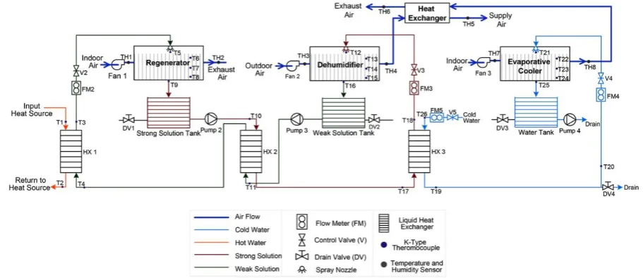
The proposed hybrid system is mainly composed of a dehumidifier, a regenerator, an 78
evaporative cooler and an air-to-air heat exchanger, as shown in Fig. 1. Three processes 79
are involved during operation, namely: dehumidification, regeneration and evaporative 80
cooling. Additionally, the airstream from the evaporative cooler is used to cool the dry 81
air to meet the supply requirement in the air-to-air heat exchanger. After 82
dehumidification, the dilute solution flows into the weak solution storage tank and is 83
delivered by magnetic-driven pump to a heat exchanger (HX2), where the weak 84
solution is pre-heated before being heated by heat source. To enhance the 85
dehumidification performance, cold water cools the strong desiccant solution prior to 86
88
Fig. 1. Schematic graph of the membrane-based dehumidification cooling system
89
Membrane-based units for the dehumidifier and regenerator are designed with a 90
dimension of 410mm (Length) × 230mm (Width) × 210mm (Height), as depicted in 91
Fig. 2. For the evaporative cooler with the same dimension, air channels are formed by 92
fibre without membrane sheets, which provides wet surface as cold water flowing 93
downwards. 94
[image:6.595.154.432.454.668.2]95
Fig. 2. Photo of the membrane-based unit
96
2.1 Experiment method
98
A boiler is utilized as the heat source for regeneration in the experiment and CaCl2 99
solution is selected as the liquid desiccant. A photo of the system test rig is presented 100
in Fig. 3. Insulations are applied for air ducting, pipe work and heat exchangers to 101
reduce the surrounding effects. Main experimental equipment with their specifications 102
is provided in Table 1. 103
[image:7.595.117.477.236.495.2]104
Fig. 3. Test rig photo
105
Table 1. Specifications of main equipment
106
Equipment Properties Manufacturer
Magnetic pump
Power 15 W
Shanghai Jiaxing
Pumps Co., Ltd. Maximum frequency 50 Hz
Maximum speed 2600 r/min
Maximum capacity 10 L/min
AC axial fan Power 45W ebm-papst Mulfingen
GmbH & Co. KG Nominal speed 2800 min-1
Boiler
Capacity 3kW
Wilo SE Supply temperature range 50-80°C
Circulating pump 45W
Water flow rate 0-6 L/min
Main measurement instruments with their respective accuracies are listed in Table 2. 107
Series of K-type thermocouples are employed to measure temperatures of desiccant 108
solution and water flows. Humidity and temperature probes are installed at all air inlets 109
and outlets, and associated air velocities are measured with an anemometer. A 110
hydrometer is used to obtain the solution density. Thus, CaCl2 solution concentration 111
ratio can be determined with correlation on a basis of solution density and temperature 112
[11]. Moreover, volumetric flow rates of liquid flows (i.e. desiccant solution and water) 113
are measured by float-style flow meters, which are calibrated with water at 20°C. In 114
order to equate an actual desiccant solution flow rate in dehumidifier and regenerator 115
units with a reading from the flow meter, the correction correlation given in literature 116
[12] is needed: 117
sol w ( fl fl sol) w ( fl fl w) sol
v v m V m V (1)
where, vsol and vw are volumetric flow rates of the desiccant solution and water 118
respectively, L/min. sol and w are densities of solution and water, kg/m3. For the 119
flow meter, the float weight (mfl) is -3
2.1 10 kg and volume (Vfl) is -6 3
0.25 10 m . 120
Table 2. Specifications of measurement instruments
121
Devices Measurement Range Accuracy
RS K-type thermocouple probe 0-1100°C ±0.75%
Sensirion EK-H4 humidity sensor -40 - +125°C ±0.3%
0 - 100% RH ±2%
Parker liquid flow indicator 4-22 L/min ±2%
Testo thermo-anemometer 405 0-10 m/s ±5%
Brannan hydrometer 200 Series 1.0-1.6 g/m3 ±2%
The experimental data are processed with uncertainty analysis, which provides the 123
associated error of a calculated value. Error bars are included in the graphs for 124
experimental result analyses. 125 2 2 1 ( )
i N y x i i y U Ux (2)
where, Uxi is uncertainty of each measured variable xi.
126
2.2 Evaluation Method
127
Dehumidification process
128
The dehumidification performance is assessed by moisture removal rate. 129
r air_DH ( in_DH out_DH)
M m (3)
where, Mrrepresents moisture removal rate, g/s. mair_DH is mass flow rate of air passing 130
through the dehumidifier, kg/s, in_DH and out_DH are air humidity ratios at inlet and 131
outlet of the dehumidifier, kg/kgdryair. Thermophysical properties of the moist air are 132
determined using equations referred to literature [13]. 133
The dehumidification effectiveness is defined as the ratio of actual change in moisture 134
content to the maximum moisture transfer. 135 in_DH out_DH DH in_DH eq_DH
(4)
where, DH is the dehumidification effectiveness. eq_DH is equilibrium humidity ratio 136
of desiccant solution at the inlet condition, kg/kgdryair. Under the equilibrium state, it is 137
given by literature [14]: 138 sol eq_DH A sol 0.62198 P P P
where, PA is atmospheric pressure, Pa, and Psolis vapour pressure of CaCl2 solution at 139
a given temperature, Pa, which can be calculated with the empirical correlation derived 140
by literature [15]. 141
Based on the enthalpy difference between the inlet and outlet air in the dehumidifier, 142
the dehumidifier cooling output is determined as: 143
DH_c air_DH( in_DH out_DH)
Q m h h (6)
where, QDH_cis the dehumidifier cooling output, W. hin_DH and hout_DH are specific 144
enthalpies of air at inlet and outlet of the dehumidifier, J/kg. 145
Regeneration process
146
The regeneration performance is evaluated by moisture addition rate. 147
a air_RE ( out_RE in_RE)
M m (7)
where, Ma represents moisture addition rate, g/s. mair_RE is regenerator air mass flow 148
rate, kg/s. in_RE andout_RE are humidity ratios of air entering and leaving the 149
regenerator, kg/kgdryair. 150
The thermal input power of the regenerator is determined as: 151
RE w_RE p_w_RE( w_in w_out)
Q m c T T (8)
where, QREis the regenerator thermal input power, W. mw_REand cp_w_RE are water mass 152
flow rate, kg/s, and specific heat capacity, J/kg, in the heating circuit. Tw_in and Tw_out
153
are hot water supply and return temperatures respectively, °C. 154
Coefficient of performance
155
c air_DH( in_DH supply)
Q m h h (9)
where, Qc is the system total cooling output power, W. hsupplyis specific enthalpy of 157
supply air, J/kg. 158
The hybrid system overall coefficients of performance (COP) are defined as: 159
c th
RE
COP Q
Q
(10)
c el
e
COP Q
W
(11)
where, COP is thermal coefficient of performance and th COP is electrical coefficient el 160
of performance. We is electrical consumption, W. 161
3. Results and Discussion
162
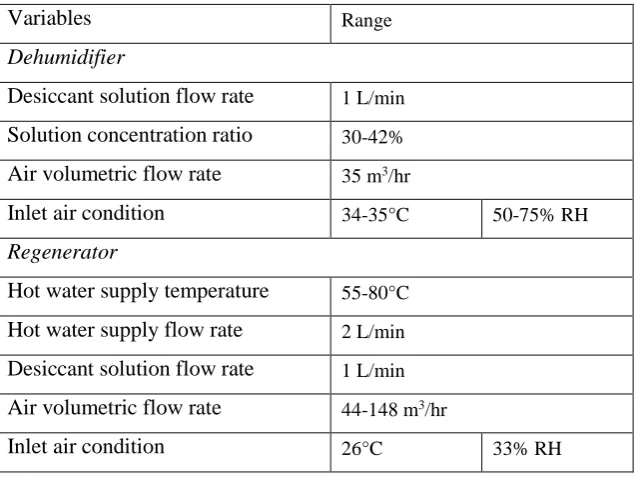
Table 3 presents operating variables for the experiment. Effects of operating variables 163
on the dehumidifier and regenerator performances are investigated at CaCl2 solution 164
[image:11.595.140.458.523.762.2]concentration ratio of 39%. 165
Table 3. Operating variables for experiment
166
Variables Range
Dehumidifier
Desiccant solution flow rate 1 L/min
Solution concentration ratio 30-42%
Air volumetric flow rate 35 m3/hr
Inlet air condition 34-35°C 50-75% RH
Regenerator
Hot water supply temperature 55-80°C
Hot water supply flow rate 2 L/min
Desiccant solution flow rate 1 L/min
Air volumetric flow rate 44-148 m3/hr
Evaporative cooler
Inlet air condition 26°C 33% RH
Cold water supply temperature 10°C
Cold water supply flow rate 12 L/min
3.1 Effect of inlet air relative humidity on dehumidification performance
167
The inlet air temperature for the dehumidifier is set at 34.6°C and relative humidity 168
varies from 46% to 70%. It can be seen from Fig. 4(a) that the dehumidifier 169
performance increases with the inlet air relative humidity at the constant inlet air 170
temperature. The dehumidifier moisture removal rate doubles as air relative humidity 171
increases from 46% to 70% and the dehumidification effectiveness improves by 36.9%. 172
The increase in the moisture removal rate is caused by the greater vapour pressure 173
difference between the airstream and desiccant solution. 174
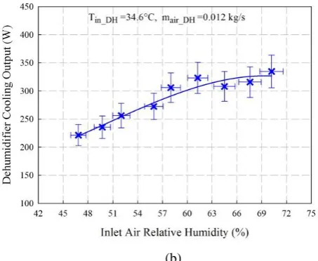
Over the investigated inlet air relative humidity range, the higher inlet air relative 175
humidity leads to more cooling output as shown in Fig. 4(b). The dehumidifier cooling 176
output increases from 221.4W to 334.7W as air relative humidity increases from 46% 177
to 70%. However, as the relative humidity gets higher than 63%, the increase in the 178
cooling output becomes smaller. It indicates that the dehumidifier cooling output 179
approaches the maximum capacity with further increase in air relative humidity. 180
181
(a)
183
(b)
[image:13.595.184.411.71.257.2]184
Fig. 4. Effects of inlet air relative humidity on (a) moisture removal rate and dehumidification
185
effectiveness and (b) dehumidifier cooling output
186
3.2 Effect of air flow rate on regeneration performance
187
Tests are carried out to investigate air flow rate effect on the regeneration performance. 188
At an inlet air temperature of 26°C and relative humidity of 33%, the regenerator air 189
flow rate is increased from 43.82m3/hr to 148.44m3/hr, while the hot water is kept at a 190
temperature of 61°C. Though the increase of regenerator air flow rate leads to reduction 191
in the moisture addition capability, the moisture addition rate takes both the moisture 192
content change and air flow rate into account. As observed in Fig. 5, there is an increase 193
in the moisture addition rate. However, the moisture addition rate only increases by 194
0.04g/s over the investigated air flow rate range, which indicates that the impact of the 195
[image:14.595.185.407.70.241.2]
197
Fig. 5. Effects of air flow rate on moisture addition rate
198
3.3 Effect of hot water temperature on regeneration performance
199
To identify the effect of hot water temperature on regeneration performance, the hot 200
water is supplied in the temperature range from 55°C to 80°C. As presented in Fig. 6, 201
the regeneration performance improves accordingly with hot water temperature under 202
the constant regenerator inlet condition. The moisture addition rate increases by 75% 203
as the hot water temperature increases from 55°C to 80°C. The increase in hot water 204
temperature results in higher desiccant solution temperature in the regenerator, and thus 205
higher vapour pressure is obtained in solution side. Then the greater vapour pressure 206
difference between the desiccant solution and airstream leads to more mass transfer in 207
the regeneration process at the constant inlet air condition. Moreover, as the hot water 208
temperature is above 70°C, it is noted that the increase in the moisture addition rate 209
becomes smaller. The variation in the air humidity ratio across the regenerator is only 210
0.06g/kgdryair as the hot water temperature rises from 70°C to 80°C. Therefore, 211
regarding to the feasibility of utilizing renewable energy as heat source, at the given 212
operating condition, hot water supply temperature up to 70°C is sufficient for adequate 213
215
Fig. 6. Effect of hot water temperature on moisture addition rate
216
3.4 Effect of concentration ratio on system performance
217
According to the operative concentration ratio level of CaCl2, investigations are 218
conducted with solution concentration ratio ranging from 30% to 42%. The 219
dehumidification effectiveness increases evidently with concentration ratio as shown in 220
Fig. 7. For desiccant solution concentration ratio below 33%, there is only slight 221
difference in the dehumidifier effectiveness, which implies the operative concentration 222
ratio needs to be at least above 33%. As solution concentration ratio gets higher than 223
33%, the dehumidifier effectiveness improves more significantly and reaches up to 0.54 224
at concentration ratio of 42%. For operation of the liquid desiccant system, higher 225
desiccant solution concentration ratio would be better for dehumidification 226
performance. However, the use of highly concentrated solution may cause salt 227
crystallization, which may lead to risks of fluid mal-distribution, channel blockage, 228
high pumping pressure, and membrane fouling. On the other hand, the dehumidifier 229
cooling output also increases from 181.0W to 428.8W with the increase of solution 230
concentration ratio, which is related to the higher moisture removal rate in the 231
233
Fig. 7. Effects of solution concentration ratio on dehumidification effectiveness and cooling output
234
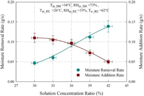
It can be observed from Fig. 8 that as concentration ratio increases from 30% to 42%, 235
the dehumidifier moisture removal rate improves from 0.05g/s to 0.14g/s while the 236
regenerator moisture addition rate decreases from 0.11g/s to 0.05g/s. For the 237
dehumidification process, the driving force caused by the vapour pressure difference 238
between airstream and desiccant solution gets higher for stronger solution, which thus 239
leads to greater moisture removal rate in the dehumidifier. On the contrary, in the 240
regeneration process, desiccant solution with higher concentration ratio has lower 241
capability for moisture addition due to the lower vapour pressure. 242
To allow continuous operation of the overall system, the performance of regenerator 243
should match with that of dehumidifier otherwise mass imbalance occurs, which would 244
result in some problems such as the dilution of desiccant solution over time. For the 245
investigated operating condition, the dehumidification and regeneration processes are 246
balanced at desiccant solution concentration ratio of 36%, as the dehumidifier moisture 247
removal rate equals to the regenerator moisture addition rate. Thus, measures are 248
needed to facilitate the regenerator performance for the stronger desiccant solution 249
while the dehumidification performance should be improved at lower concentration 250
COPel reach up to 0.70 and 2.62 respectively at concentration ratio of 36%, while the 252
supply air temperature is provided at 20.4°C. Hence, the results reveal that the hybrid 253
system is feasible for applications, and the supply air condition could meet the 254
comfortable indoor environment requirement. 255
[image:17.595.174.423.191.357.2]256
Fig. 8. Effects of solution concentration ratio on moisture removal and addition rates
257
4. Conclusions
258
A membrane-based hybrid liquid desiccant dehumidification cooling system is 259
developed to provide efficient temperature and humidity controls in hot and humid 260
regions. The experimental results indicate the system with CaCl2 desiccant solution is 261
feasible for dehumidification and cooling purposes under the tested hot and humid 262
conditions. Impacts of operating variables on dehumidifier, regenerator and system 263
performances are identified through experimental tests. As inlet air relative humidity 264
increases from 46% to 70% at constant temperature of 34.6°C, the dehumidifier 265
moisture removal rate doubles and dehumidification effectiveness improves by 36.9%. 266
On the other hand, the regenerator performance increases with inlet air flow rate and 267
hot water temperature. As the hot water temperature increases from 55°C to 80°C, the 268
regenerator moisture addition rate increases by 75% under the same inlet air condition. 269
dehumidification performance improves from 0.05g/s to 0.14g/s and the dehumidifier 271
cooling output doubles, while the regenerator moisture addition rate decreases by 272
54.5%. For steady system operation, mass balance between dehumidification and 273
regeneration is of vital importance. Under the investigated solution concentration ratio 274
of 36%, the supply air temperature of 20.4°C is obtained, the system thermal COPth 275
achieves up to 0.70 and electrical COPel reaches to 2.62 accordingly. 276
Acknowledgements
277
The authors gratefully acknowledge the scholarship support from the Faculty of 278
Engineering of the University of Nottingham. 279
References
280
[1] K. Daou, R. Wang, and Z. Xia, "Desiccant cooling air conditioning: a review," 281
Renewable and Sustainable Energy Reviews, vol. 10, pp. 55-77, 2006. 282
[2] X. Wang, W. Cai, J. Lu, Y. Sun, and X. Ding, "Heat and Mass Transfer Model 283
for Desiccant Solution Regeneration Process in Liquid Desiccant 284
Dehumidification System," Industrial & Engineering Chemistry Research, vol. 285
53, pp. 2820-2829, 2014. 286
[3] L.-Z. Zhang, "Progress on heat and moisture recovery with membranes: From 287
fundamentals to engineering applications," Energy Conversion and
288
Management, vol. 63, pp. 173-195, 2012. 289
[4] S. Y. Ahmed, P. Gandhidasan, and A. A. Al-Farayedhi, "Thermodynamic 290
analysis of liquid desiccants," Solar Energy, vol. 62, pp. 11-18, 1998. 291
[5] L. Mei and Y. J. Dai, "A technical review on use of liquid-desiccant 292
dehumidification for air-conditioning application," Renewable and Sustainable
293
[6] R. Qi, L. Lu, and Y. Jiang, "Investigation on the liquid contact angle and its 295
influence for liquid desiccant dehumidification system," International Journal
296
of Heat and Mass Transfer, vol. 88, pp. 210-217, 2015. 297
[7] S.-M. Huang and L.-Z. Zhang, "Researches and trends in membrane-based 298
liquid desiccant air dehumidification," Renewable and Sustainable Energy
299
Reviews, vol. 28, pp. 425-440, 2013. 300
[8] A. H. Abdel-Salam, G. Ge, and C. J. Simonson, "Thermo-economic 301
performance of a solar membrane liquid desiccant air conditioning system," 302
Solar Energy, vol. 102, pp. 56-73, 4// 2014. 303
[9] H. T. El-Dessouky, H. M. Ettouney, and W. Bouhamra, "A Novel Air 304
Conditioning System," Chemical Engineering Research and Design, vol. 78, pp. 305
999-1009, 2000. 306
[10] M. Jradi and S. Riffat, "Experimental investigation of a biomass-fuelled micro-307
scale tri-generation system with an organic Rankine cycle and liquid desiccant 308
cooling unit," Energy, vol. 71, pp. 80-93, 2014. 309
[11] Å. Melinder, Thermophysical Properties of Aqueous Solutions Used as
310
Secondary Working Fluids [Elektronisk resurs]. Stockholm: KTH, 2007.
311
[12] S. Liu, "A novel heat recovery/desiccant cooling system," PhD, Architecture 312
and Built Environment, University of Nottingham, 2008. 313
[13] P. T. Tsilingiris, "Thermophysical and transport properties of humid air at 314
temperature range between 0 and 100 °C," Energy Conversion and Management,
315
vol. 49, pp. 1098-1110, 5// 2008. 316
[14] ASHRAE, "2013 ASHRAE Handbook - Fundamentals (I-P Edition)," ed: 317
American Society of Heating, Refrigerating and Air-Conditioning Engineers, 318
[15] L. A. Cisternas and E. J. Lam, "An analytic correlation for the vapour pressure 320
of aqueous and non-aqueous solutions of single and mixed electrolytes. Part II. 321
Application and extension," Fluid Phase Equilibria, vol. 62, pp. 11-27, 1991. 322