2-D Analytical Model for Dual-Stator Machines
with Permanent Magnets
Dmitry Golovanov, Michael Galea, Chris Gerada
Division of Electrical Systems & OpticsThe University of Nottingham Nottingham, United Kingdom
Abstract – This paper proposes an analytical model that considers the torque characteristics and results in an optimum geometry for dual-stator synchronous machines with permanent magnets. The distribution of the magnetic field in the air gap is obtained by solving Neumann’s problem by using Green’s function. The results of the study shows that the dual-stator topology of synchronous machine with permanent magnets can achieve up to 1.7 times more torque when compared to conventional machine with radially magnetized magnets. This effect is achieved due to more efficient using of the volume of the machine. The analytical model presented in the paper allows fast but accurate optimization of the machine’s geometry and is used to achieve an optimal design for the considered application.
Keywords – analytical solution of Neumann’s problem; dual-stator machine; permanent magnets; synchronous electric machine
I. INTRODUCTION
The concept of the more electric aircraft (MEA) implies the development of high density power and torque characteristics in electric motors. Thus, it urges the search of novel technological solutions for motor design. Currently synchronous electrical machines with permanent magnets (PM) as well as superconducting electrical machines are the most promising in this aspect [1]. A variety of design embodiments for synchronous machines with permanent magnets exists, the most common are with radial magnetization (surface mounted PM) [2]; tangential magnetization (concentrated flux design) [3]; and Halbach’s scheme magnetization which is a combination of tangential and radial magnets [4], the less common are so called Vernier permanent magnet machine [5] and dual airgap stator permanent magnet machine [6]. This article focuses on the further development of analytical model based on fundamental solution of Laplace’s and Poisson’s equations for machines with dual-stator topologies and radially magnetized PM. This kind of dual-stator topology has several advantages in comparison to single-stator one: ability to achieve high specific power, low moment of inertia of cap-rotor, reduced cogging torque.
In Fig. 1 the most common topology of synchronous machine with radially magnetized permanent magnets is presented. Typically, the active parts of a synchronous motor with radial magnets comprise the rotor’s yoke, followed by the layers of PMs, bandage, stator’s winding and stator’s yoke. The thickness of permanent magnets mainly depends on the coercive force of magnets - ܪ and width of air gap. An optimal range of magnets thickness is between 5-20% of rotor’s radius. As you can see from Fig. 1 the internal space in
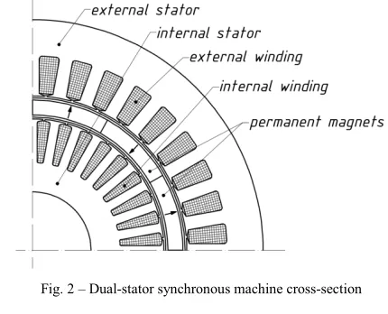
[image:1.595.325.535.221.373.2]this configuration is hollow and allows placing one more stator there – Fig. 2.
Fig. 1 – Cross-section of synchronous machine with radial magnets
Dual-stator topology has several advantages compared to conventional scheme: more efficient using of machine’s volume, reduction of rotors moment of inertia, and decreasing of cogging torque [7], [8]. Moreover, external and internal winding can be joined in series or in parallel. Therefore we can have two synchronous machine operated by internal or external winding only (in case of motor mode) or by using both of them at the same time.
Fig. 2 – Dual-stator synchronous machine cross-section
II. SOLUTION OF MAGNETOSTATIC PROBLEM FOR DUAL -STATOR MACHINE
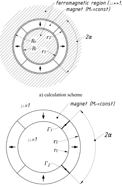
[image:1.595.321.536.496.670.2]formulation is schematically shown in Fig. 3. The calculation scheme (Fig. 3a) represents internal and external ferromagnetic regions limited by ܴ and ܴradiuses which
denote the stators boundaries. The magnetic cylinder with permanent magnets in between of ferromagnetic regions is restricted by internal and external radiuses ݎଵ and ݎଶ
[image:2.595.65.261.166.467.2]respectively. The magnetic cylinder contains 2 permanent magnets which have magnetization ܯ in radial direction
Fig. 3b.
a) calculation scheme
b) isolated magnetic cylinder with boundary conditions
[image:2.595.65.262.477.637.2]c) ferromagnetic regions with boundary conditions
Fig. 3 – Schematic representation of magnetostatic problem formulation for dual-stator machine
To receive an analytical solution of magnetic field distribution for the region ܴ≤ݎ≤ܴ we can apply the following assumptions:
- The materials of external and internal stators are not saturated and relative magnetic permeability isߤ௦௧≫
1(we can ignore the boundary condition of the outer radius of external stator – Fig. 3a);
- The permanent magnets are radially magnetized
ܯ=ܿ݊ݏݐand the relative magnetic permeability ߤ = 1 - Fig. 3b. The tangential part of
magnetization is equal to zero at any part of permanent magnets;
- The magnetic fields are plane-parallel and 3D effects are not considered;
The distribution of magnetic field in active zone was estimated as superposition of the field of isolated magnetic cylinder – Fig. 3b, Fig. 4 and influence of ferromagnetic regions of stators – Fig. 3c.
A. Solution for isolated magnetic cylinder
To define the magnetic field of isolated magnetic cylinder the solution of Laplace equation in cylindrical coordinates was considered. One of the ways to build a solution of Laplace equation is to use a Green’s functions.
The magnetic field of isolated cylinder (Fig. 3b) with permanent magnets is described by Poisson’s equation (1) in polar coordinates:
∇ଶA =ஜబ
డெೝ
డఏ , ݎଵ≤ݎ≤ݎଶ, 0 ≤ߠ≤ 2ߨ (1)
whereܣis magnetic vector potential, ܯ– magnetization of
PM in radial direction. The magnetizationܯis not changes in
ߠdirection within PM. Thereby the Neumann’s problem for magnetic cylinder can be represented as (2) with appropriate boundary conditions at߁ଵand߁ଶ(3):
∇ଶA = 0 (2)
ܪఏା =ܪఏି; ܤା=ܤି (3) ܪఏis the tangential component of magnetic strength,ܤis the
radial component of flux density. The indexes “+” and “-” are related to parameters on the different sides of boundaries. Boundary conditions (3) can be also expressed via vector potential (4);
ܣା=ܣି, ቀడఏడቁା−ቀడఏడቁି =ߤܯ (4)
The common solution of this problem is described as expression (5):
S L
dS M G GMdl
A
2 1 2
1
0
0 (5)
whereܯ – magnetization of PM,ܮ=߁ଵ+߁ଶ- Fig. 3b,ܵ– the
area of single magnet in the cylinder,ܩ– is aGreen's function for- poles magnetic cylinder, which is described as (6) [9], [10].
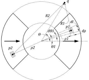
where݊– the number of harmonics of Fourier series,ߠ– the angle of field observation and ߠଵ – the angle of position of
[image:3.595.71.253.101.266.2]elementary magnetic fragment1– Fig. 4
Fig. 4 – Illustration of problem formulation for magnetic cylinder
After having done the integration of expression (5) we can receive the solutions for internal region ܣ∈{ݎ<ݎଵ} – (7),
external region ܣ∈{ݎ>ݎଶ} – (8) and for the region of
magnetic cylinderܣ ∈{ݎଵ<ݎ<ݎଶ}– (9).
ܣ= −ߤଶெగೝ∑
ቀ
మభషିభభషቁ
(ଵି) sin(݊ߠ) sin(݊ߙ)(7) ܣ= −ߤଶெగೝ∑
షቀ
మభశିభభశቁ
(ଵା) sin(݊ߠ) sin(݊ߙ)(8) ܣ = −ߤଶெగೝ∑
షቀభశି భభశቁ
(ଵା) sin(݊ߠ) sin(݊ߙ)−
−ߤଶெగೝ∑
ቀ
మభషିభషቁ
(ଵି) sin(݊ߠ) sin(݊ߙ)(9)
B. Influence of ferromagnetic region
The total solution for magnetic field produced by PMs in the internal and external air gap of dual stator machine can be described as a sum of field of isolated cylinderܣ୧,ୣ,୫ ୟand the
field of influence of the external and internal statorsܣୱ୲(10): ܣஊ=ܣୱ୲+ܣ୧,ୣ,୫ ୟ (10)
For the boundaries߁ଷand߁ସ(Fig. 3) should be fulfilled the
following boundary condition (11):
డಂ
డቚୀோ,ோ= 0
(
11)The common solution forܣୱ୲is the expression (12):
ܣୱ୲(ݎ,ߠ) =∑ୀଵ,ଷ..ቀܥݎ+ቁsin(݊ߠ) (12) where ܥ and ܤ can be found from the boundary conditions (11), Fig. 3 atݎ=ܴandݎ=ܴ– (13).
ܥ= ଶெೝఓబோమ
గቀோమିோమቁ
మభషିభభష (ଵି) +
మశభିభశభ
(ଵା)ோమ൨sin(݊ߙ), ܤ=ଶெೝఓబோమோమ
గቀோమିோమቁ
మభషିభభష (ଵି) +
మశభିభశభ
(ଵା)ோమ൨sin(݊ߙ)(13)
C. Solution for stators’ domains
The magnetic field in the external ܴ≤ݎ≤ܴ௫௧ and
internal ܴ≤ݎ≤ܴ௧ stators’ domains are described by
common solution of Laplace’s equation (14, 15).
ܣ௦௧_௫௧=∑ቀܥଵݎ+భቁsin(݊ߠ) (14)
ܣ௦௧_௧=∑ቀܥଶݎ+మቁsin(݊ߠ) (15) The coefficients ܥଵ, ܥଶ,ܤଵ, ܤଶ can be found from the
[image:3.595.308.560.476.587.2]boundary conditions (16 - 19) at the inner and outer surfaces of stators – Fig. 5.
Fig. 5 – Boundaries of stators’ domains
atܴ௧: ܣ௦௧_௧(ܴ௧,ߠ) = 0 (16)
atܴ: ܣ௦௧_௧(ܴ,ߠ) =ܣ(ܴ,ߠ) +ܣୱ୲(ܴ,ߠ) (17)
atܴ: ܣ௦௧_௫௧(ܴ,ߠ) =ܣ(ܴ,ߠ) +ܣୱ୲(ܴ,ߠ) (18)
atܴ௫௧: ܣ௦௧_௫௧(ܴ௫௧,ߠ) = 0 (19)
Functions ܣ(ݎ,ߠ), ܣ(ݎ,ߠ) and ܣ௦௧(ݎ,ߠ) are defined in
sections A andB. Thus for the unknown coefficients ܤଵ,ܥଵ,
ܤଶ,ܥଶwe can obtain the expressions (20 - 23) respectively.
ܤଵ= − ൫ܣ݁(ܴ݁,ߠ)+ܣూ(ܴ݁,ߠ)൯ோೣ
ୱ୧୬(ఏ)ቈ൬ೃೣೃ൰ିቀೃೣೃቁ (20) ܥଵ= −ோభ
ೣ
మ (21)
ܤଶ= − ൫ܣ݅(ܴ݅,ߠ)+ܣూ(ܴ݅,ߠ)൯ோ
ୱ୧୬(ఏ)ቈ൬ೃೃ൰ି൬ೃೃ൰ (22) ܥଶ= −ோమ
మ (23)
D. Solution for stators’ winding
The 3-phase stators’ winding was replaced with current sheets at the surfacesܴandܴ– Fig. 6. The current sheet of
phase Aଵ is marked by bold line. It can be represented as
Fourier series (24).
ܬଵ(ߠ) =ସగబ∑ଵcosቀߥ݊ቂߠ−గ +ߠቃቁsinቀ݊గቁ (24)
Fig. 6 – Position of current sheet for phaseA1of dual-stator machine
Taking into account boundary conditions (25, 26) the solution of Laplace’s equation for phase Aଵ (27) can be
represented as (28).
atݎ=ܴ:డడఽభ=ߤܬଵ (25)
atݎ=ܴ:డడఽభ= 0 (26) ∇ଶA
ଵ= 0∀ܴ≤ݎ≤ܴ (27)
Aଵ= −ߤ݅ݓ∑୬ଵమቂ(a୬+ 1)ቀୖ୰ቁ
ି୬
+ (a୬− 1)ቀୖ୰ቁ ି୬
ቃ. . × cosቀnቂθ − + θቃቁsinቀ݊గቁ (28)
where݅– peak phase current,ݓ – number of turns per one
coil of phaseܽis expressed as (29).
ܽ= −ோ
మାோ మ
ோమିோమ (29) The similar expressions can be revealed for other phases (30 - 34). The total field produced by current sheets Fig. 6 is a sum of separately solutions (27, 29 – 33).
ܣଵ= −ߤ݅ݓ∑ଵమቂ(ܽ+ 1)ቀோቁ ି
+ (ܽ− 1)ቀோቁ ି
ቃ. . × cosቀ݊ቂߠ−ହగ+ߠቃቁݏ݅݊ቀ݊గቁ (30) ܣଵ= 2ߤ݅ݓ∑ଵమቂ(ܽ+ 1)ቀ
ோቁ
ି
+ (ܽ− 1)ቀோቁ ି
ቃ. . × cosቀ݊ቂߠ−ଶగ +ߠቃቁݏ݅݊ቀ݊గቁ (31)
Aଶ= −ߤ݅ݓ∑୬ଵమቂ(a୬+ 1)ቀ
୰ ୖቁ
୬
+ (a୬− 1)ቀୖ୰ቁ ୬
ቃ. . × cosቀnቂθ − + θቃቁsinቀ݊గቁ (32) ܣଶ= −ߤ݅ݓ∑ଵమቂ(ܽ+ 1)ቀ
ோቁ
+ (ܽ− 1)ቀோቁ
ቃ. . × cosቀ݊ቂߠ−ହగ+ߠቃቁݏ݅݊ቀ݊గቁ (33) ܣଶ= 2ߤ݅ݓ∑ଵమቂ(ܽ+ 1)ቀ
ோቁ
+ (ܽ− 1)ቀோቁ
ቃ. . × cosቀ݊ቂߠ−ଶగ +ߠቃቁݏ݅݊ቀ݊గቁ (34)
Expressions (28, 30 – 34) are given for 3-phase winding with120°of shifting in time domain between phases. So, for
the starting timeݐ= 0we haveܬେଵ= −ଵଶܬଵ= −ଵଶܬଵ,ܬେଶ= −ଵଶܬଶ= −ଵଶܬଶ.
E. Numerical verification
The analytical solution given in the previous section was verified by Finite element analysis (FEA). As an example the model of machine with the parameters, mentioned in Table 1 was built. In this comparison of analytical and numerical results the slotting and saturation effects are not considered. The machine is considered as synchronous motor.
TABLE I PARAMETERS OF DUAL-STATOR MACHINE
Parameter Symbol Value
Magnetization of PMs ܯ 106A/mm
Relative permeability of PMs ߤ 1
Number of pole pairs 6
Axial length ܮ 100 mm
Internal radius of inner stator ܴ௧ 127 mm External radius of inner stator ܴ 182.5 mm Internal radius of outer stator ܴ 215 mm External radius of outer stator ܴ௫௧ 281.5 mm
Internal radius of PMs cylinder ݎଵ 185 mm
External radius of PMs cylinder ݎଶ 212.5 mm Half of magnet pole-arc ߙ ଶ୮(15°) Peak value of current load for outer
and inner current sheet ܬ 1.41·105A/m
The results ofFEA and analytical solution were received and the pictures of magnetic flux lines for nonload condition are shown in Fig. 7a, b.
[image:4.595.323.538.398.513.2]a)FEA b) analytical result
Fig. 7 – The distribution of magnetic field within dual-stator motor for nonload condition (a –FEA, b – analytical result)
The radial and tangential components of flux density and field strength can be obtained via expressions (35 – 36).
ܤ=ଵడడఏ, ܪ=ఓఓଵబడడఏ (35) ܤఏ= −డడ, ܪఏ= −ఓఓଵబడడ (36)
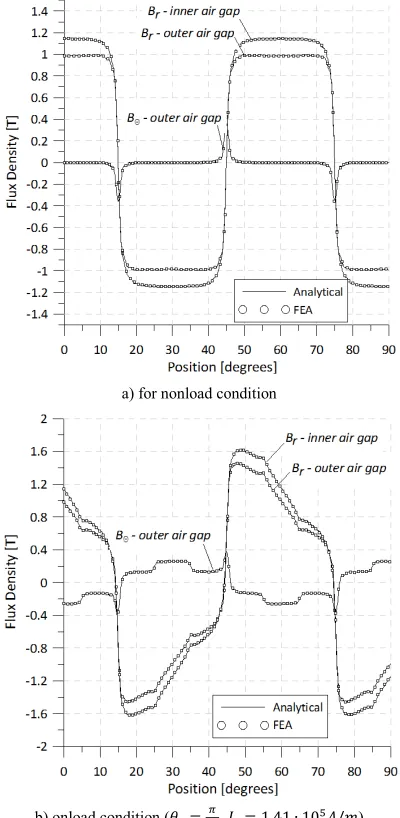
The numerical solutions for the normal and tangential components of flux density taken alongside the middle line of internalݎ= 183.75݉ ݉ and externalݎ= 213.75݉ ݉ air gaps were compared with the analytical results - Fig. 8a, b. All calculations are considered for the arc0 ≤ߠ≤గଶ– Fig. 7a, b. Good agreement can be observed for both nonload– Fig 8a and loaded condition (at power angle -ߠ=ଶగ and peak value of
[image:4.595.40.290.467.663.2]10ହܣ ݉ൗ ) – Fig. 8b. The analytical calculations are given for ݊= 33odd harmonics.
a) for nonload condition
b) onload condition (ߠ=గ
[image:5.595.63.263.87.496.2]ଶ,ܬ= 1.41 ∙ 10ହܣ/݉)
Fig. 8 – Distribution of radial and tangential component of flux density in air gaps for dual-stator machine
III. THE TORQUE CHARACTERISTICS
To investigate the motor torque and to find the optimal dimensions of magnetic cylinder the relative thickness of PM Δ =(ݎଶ−ݎଵ)/ݎଶ is introduced in the solution. The parameter Δ can be varied in the range of 0 – 1. So atΔ = 0 the total torque of dual-stator machine is zero while atΔ = 1only inner stator torque is zero.
The electromagnetic torque of the motor with dual-stator topology can be estimated by using the Maxwell stress tensor [11] as a sum (37) of torques produced by internal (38) and external (39) stators.
ܶ௧௧=ܶ+ܶ (37)
ܶ=ೌோ_
మ
ఓబ ∫ ܤ_൫ܴ_,ߠ൯
ଶగ
ܤఏ_൫ܴ_,ߠ൯݀ߠ (38)
ܶ=ೌோ_
మ
ఓబ ∫ ܤఏ_൫ܴ_,ߠ൯
ଶగ
ܤఏ_൫ܴ_,ߠ൯݀ߠ (39)
Whereܴ_ = (ܴ+ݎଵ) 2⁄ – middle line in the internal air
gap;ܴ_ = (ܴ+ݎଶ) 2⁄ – middle line in the external air gap; ܤ_൫ܴ_,ߠ൯, ܤఏ_൫ܴ_,ߠ൯ – functions of radial and
tangential components of total flux density in the internal air gap; ܤ_൫ܴ_,ߠ൯,ܤఏ_൫ܴ_,ߠ൯ – functions of radial and
tangential components of total flux density in the external air gap;ܮ– axial length of machine.
The electromagnetic torque of motor strictly depends on the main dimensions, current load and magnetic induction in the air gap. So, if we fix current load, speed of rotation, magnet pole-arc -ߙ, the main radius of external stator -ܴand
the air gap width we can rewrite the expression (34) as a function of number of polesand relative thickness of PMΔ (40).
ܶ௧௧=்݂(Δ, ) +்݂(Δ, ) (40) As an example for the parameters mentioned in Table 1 the torque distribution map of total torque is shown in Fig. 9. The peak current load is taken 1.41·105A/m for the internal and
external stators (at the radiuses ܴandܴ). The peak phase
current of internal and external stator can be estimated via peak current load as (41).
݅=బ௪ గோ, (41)
whereݓ = 33number of turns per phase coil,݉ = 3number of phases, ܴ, – internal and external radiuses, ܬ – peak current load. Any relative thickness of PM from Fig. 9 corresponds to a fixed number if internal stator radiusܴand ܴ= 215݉ ݉. The peak phase current of external stator is
fixed and calculated (38) but for the internal stator it’s changing with decrease ofܴ(so, the peak current load is the same and fixed for all phases).
Fig. 9 – The map of torque distribution for dual-stator machine
[image:5.595.323.540.480.660.2]The dependence of torque on pole pairs at optimal relative thickness of PMΔ = 0.15is shown in Fig. 10. In the range of
= 1 − 50 we can observe decrease in torque. The torque contribution in total torque is 40 – 45% for the internal stator and 55 – 60% for the external stator for the given range of pole pairs.
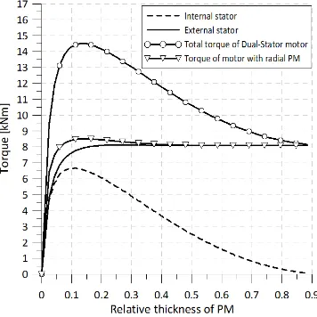
[image:6.595.73.256.307.482.2]In Fig. 11 torque contribution of internal and external stators and their total torque for dual-stator machine from Fig. 2 are compared to radial magnets machine with conventional topology from Fig. 1 for the case of pole pairs= 6. It can be seen that the peak of total torque and the peak torque provided by internal stator are reached at Δ ≈ 0.1 − 0.15and smoothly decrease whenΔrises. According to the results of calculations the peak torque of the dual-stator synchronous motor with the parameters mentioned above is 14.5 kNm. The contribution of internal stator in total torque (at optimalΔ = 0.13) is 6.6 kNm (~45.5%) and external stator is 7.9 kNm (~54.5%). The torque of machine with conventional topology with the same main dimensions as the dual-stator one has value of 8.5 kNm which is 58.6% of total dual-stator motor torque.
Fig. 10 – Torque and pole pairs correlation for dual-stator motor at optimal relative thickness of permanent magnets (Δ = 0.15)
Fig. 11 – Estimation of torque for 12-poles dual-stator and conventional machine with radial magnets
IV. CONCLUSION
Theoretical investigations of synchronous machine with dual-stator topology demonstrate enhanced torque characteristics in comparison to conventional scheme of machine with radial magnets. Due to the more efficient using of internal volume the electromagnetic torque of machine can be increased up to 1.7 times after this kind of modernization. Therefore, the machine has a potential for application in the systems with a strong torque density and power density requirements such as aerospace application or for electric vehicle with enhanced requirements to the torque and power density. The analytical solution presented in the paper allows optimization of dual-stator machine power characteristics for different number of pole pairs. At the same time the analytical solution can be used for geometry optimisation defining suitable relation between the size of internal and external stator and dimension of permanent magnets.
V. REFERENCES
[1] Bulent Sarlioglu, Casey T. Morris "More Electric Aircraft: Review, Challenges, and Opportunities for Commercial Transport Aircraft"IEEE TRANSACTIONS ON TRANSPORTATION ELECTRIFICATION, VOL. 1, NO. 1, JUNE 2015
[2] Adel Bellara, Yacine Amara, Georges Barakat, and Brayima Dakyo "Two-Dimensional Exact Analytical Solution of Armature Reaction Field in Slotted Surface Mounted PM Radial Flux Synchronous Machines" IEEE TRANSACTIONS ON MAGNETICS, VOL. 45, NO. 10, OCTOBER 2009
[3] Ji-Min Kim, Seung-Hee Chai, Myung-Hwan Yoon, and Jung-Pyo Hong "Plastic Injection Molded Rotor of Concentrated Flux-Type Ferrite Magnet Motor for Dual-Clutch Transmission"IEEE TRANSACTIONS ON MAGNETICS, VOL. 51, NO. 11, NOVEMBER 2015
[4] M. Galea, Z. Xu, C. Tighe, T. Hamiti, C. Gerada, and S. Pickering, "Development of an aircraft wheel actuator for green taxiing," in Electrical Machines (ICEM), 2014 International Conference on, 2014, pp. 2492-2498.
[5] High-Power-Factor Vernier Permanent-Magnet Machines Dawei Li; Ronghai Qu; Thomas A. Lipo IEEE Transactions on Industry Applications Year: 2014, Volume: 50, Issue: 6 Pages: 3664 - 3674.
[6] Dual airgap stator- and rotor- permanent magnet machines with spoke-type configurations using phase-group concentrated-coil windings Wenliang Zhao; Byung-il Kwon; Thomas A. Lipo 2015 IEEE Energy Conversion Congress and Exposition (ECCE) Year: 2015
[7] Chun-Yu Hsiao, Sheng-Nian Yeh and Jonq-Chin Hwang "Design of High Performance Permanent-Magnet Synchronous Wind Generators" ISSN, Energies 2014, 7
[8] Shuangxia Niu, K.T. Chau "A Permanent-magnet double-stator integrated-starter-generator for hybrid electric vehicles" IEEE Vehicle Power and Propulsion Conference (VPPC), September 3-5, 2008, Harbin, China, CONFERENCE PAPER
[9] L. Kovalev, Y. Kavun, D. Golovanov. "The limiting characteristics of synchronous machines with permanent magnets and high-temperature
superconductors" // Electricity – 2008. – №12
[10] PhD. thesis: "Synchronous high temperature superconductor motors with permanent magnets", D. Golovanov, Moscow aviation institute, 2010. [11] Thierry Lubin, Smail Mezani, and Abderrezak Rezzoug "2-D Exact
[image:6.595.74.252.518.696.2]