ΦAbstract – An investigation into the solution dependence of a conjugate heat transfer computational fluid dynamics (CFD) model of a synchronous generator, with respect to meshing, has been carried out. Utilising CFD as a tool for investigating the airflow and thermal performance of electrical machines is increasing. Meshing is a vital part of the CFD process, but its importance is often misunderstood or overlooked in the context of electrical machine analyses; partly due to the relative mesh independency of the finite element analysis (FEA) numerical method. This paper demonstrates how a relatively complex, air-cooled generator CFD model can be considerably influenced by changes in the mesh. Flow rate, velocity and windage effects are assessed as a function of the mesh adopted. Mesh changes have been shown to affect the mass flow rate through a single vent by up to 55% and the associated heat transfer coefficient by 128%.
Index Terms-- Generators, Cooling, Fluid Dynamics, Thermal Analysis, Thermal Engineering, Rotating Machines, Numerical Simulation, Energy Efficiency, Vents.
I. INTRODUCTION
arge electrical machines often feature core cooling vents to reduce the high thermal resistances to cooling surfaces. The air vents increase surface area and shorten conduction paths to the cooling flows [1, 2]. Vents are particularly effective for cooling machines with long core lengths, as they may be used to target hotspots, which are otherwise difficult to remove with a non-vented cooling arrangement. Improved airflow and thermal analysis directly increases machine efficiency [3, 4]. However, the design of venting an electrical machine core is not straightforward, as they displace active material, re-distribute flow and contribute to additional windage losses.
Understanding the impact of introducing vents and their design is very difficult through common electrical machine thermal design tools such as finite element analysis (FEA) or lumped parameter thermal networks (LPTN). Computational Fluid Dynamics (CFD) allows airflow analysis of electrical machines with conjugate heat transfer modelling of both fluid and solid regions [5].
A conjugate heat transfer CFD model was created to investigate rotor and stator vent cooling. The model was set
ΦFinancial support from the EPSRC Impact Acceleration Account, is
gratefully acknowledged – grant number EP/K503800/1.
P. H. Connor (email:[email protected]) and C. N. Eastwick ([email protected]) are with the Fluids and Thermal Engineering Research Group, S. J. Pickering ([email protected]) is with the Composites Research Group and C. Gerada ([email protected]) is with the Power Electronics, Machines and Control Research Group, all based within the Faculty of Engineering, University of Nottingham, Nottingham, UK. R. Rolston ([email protected]) is with Cummins Generator Technologies, Peterborough, UK).
up to enable parametric adjustments to the vent sizes and positions and for solving with conjugate heat transfer. To enable a detailed study to be undertaken, the components modelled were simplified down to a core-only section, which was limited to the axial extent of the rotor and stator laminations and this was surrounded by fluid. It was observed that the solution in a vented machine model was highly mesh dependent. Parametric changes were made to the mesh distribution in four particular regions encompassing the airgap as well as the rotor and stator vents. These were found to have a specific impact on the solution.
CFD has been commonly been used for airflow modelling of electrical machines for around 15 years [2, 6, 7] and it is becoming more utilised for conjugate heat transfer modelling [8, 9]. Conjugate heat transfer modelling may be used to simultaneously solve conductive and convective heat transfer through neighbouring solid and fluid regions, respectively [10]. Meshing of these models is important in CFD, as solutions are highly mesh dependent [10, 11]. This paper demonstrates the particular importance for the meshing of highly complex electrical machine models such as those incorporating core vents.
Accurate thermal solutions require accurate airflow modelling. Whether CFD is being used to model only flow, to extract heat transfer coefficients to be implemented in LPTN or FEA modelling [5], or for integral conjugate heat transfer analysis [12], the correct airflow model is required as the foundation for the thermal model.
CFD modelling of electrical machine airgap regions is well understood. The flow in this area is complex due to the narrow channels with often blended boundary layers. Heat transfer can be challenging to determine using correlations for narrow channels, due to the dependency on flow regime, non-uniform flow profiles, significant entrance and exit losses and complications caused by rotational effects [13]. A core with rotor and stator vents poses a particular modelling challenge, due to the high number of flow paths. The delicate balance of the pressure distributions which dictate the flow can be affected by inaccuracies in the model setup. This has been shown to be affected by mesh distribution.
Whilst mesh refinements have been discussed in the context of electrical machines [14, 15], they have not been demonstrated on a realistic, complex machine topology including core vents in a conjugate heat transfer scenario.
The cases presented in this paper demonstrate variations in the solution caused only by changes in the mesh. The geometry and solver setup, including boundary conditions, remained constant for all cases. The highlighted changes were selected due to their significance in the context of thermal management of electrical machine design. This work
Stator and Rotor Vent Modelling in a MVA rated
Synchronous Machine
P. H. Connor, C. N. Eastwick, S. J. Pickering, C. Gerada, R. Rolston
is a robust verification looking at mesh sensitivity, rather than a validation. This paper demonstrates the importance of studying mesh independency as part of the CFD process, which should be routinely carried out. Only after this process should the CFD model be compared to experimental data for validation.
The meshing detail presented here is in the context of a conjugate model, which is highly constrained by the high number of fluid and solid geometrical bodies. However, the data presented in this paper is from an airflow-only solution of the model.
II. CFDMETHODOLOGY
The four main stages of the CFD process are geometry creation, mesh generation, solving and post-processing. These stages are inter-related which demands an understanding of all elements and their co-dependency. An overview of the methodology for each stage is described in subsequent sections below. Particular focus has been made on describing the important meshing regions which have been identified as having a particular effect on obtaining an accurate solution, as explained in the introduction.
The commercial CFD code ‘ANSYS Fluent V15’ [10] was used for the CFD presented in this paper. ‘ANSYS Workbench’ was used to manage the large number of CFD mesh manipulations and solution runs.
Whilst the study presented here was academic by nature, a constraint of the work was that the computational capabilities had to reflect those which would typically be utilised in industry. This was to ensure the findings from this investigation remained industrially relevant and may be immediately implemented into industrial thermal analysis and design practices. The PC used for all CFD processes had quad core, I7, 3GHz CPUs running hyper-threading and 24GB RAM.
A. CFD Geometry
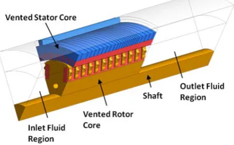
A typical synchronous generator comprises the main exciter, rotor and stator core and fan components which are enclosed within a casing in a single-ended ventilation arrangement. However, it is currently too computationally expensive to create a full 360° conjugate heat transfer model, at the physical size of MW rated machines, for use as a design optimization tool for the vented flow system.
Figure 1 shows the simplified 45° sector vented core geometry used for this work, which was created in ANSYS Design Modeller. The simplified geometry comprises a generic shaft, rotor and stator core with surrounding fluid regions. The periodic, simplified geometry reduces cost and enables a more in-depth investigation into the impact of vent sizing and mesh parameters.
There are upwards of 20 radial stator and 20 radial rotor vents within this model. Stator vents are produced by parting laminations. The rotor and stator vents are both sized to total 8% of the axial core length. These are separated by ‘I-beams’. These are required in the model due to their influence on the flow and are represented by ‘thin’ surfaces. Stator vents are frequently spaced along the core length. An axial rotor duct feeds air from the front face of the core
through to the rotor’s radial ‘finger’ vents which exhaust cooling air into the airgap. The rotor vents are grouped near the machine’s hotspot region.
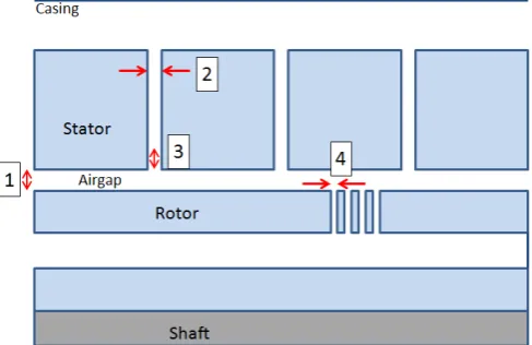
Generators pose a particular meshing challenge due to the range of dimensions and complex shapes, with narrow gaps of a few millimetres through to large open spaces with length scales two orders of magnitude larger. Figure 2a shows a simplified schematic (reduced vent count) of a section through the domain to highlight the boundary locations.
[image:2.595.311.545.343.488.2]Further slicing of the geometry, shown in Figure 2b, is required to achieve the high quality of meshing, which is essential for achieving correct airflow results, as well as to allow different physics approaches to be implemented in the appropriate zones. Solid red lines show the positions for cylindrical slicing of the domain, about the central rotation axis. Rotation modelling involved defining a rotating inner and stationary outer domain, separated by the central interface (see red dotted line, Figure 2b). The two meshing domains enable the relative rotational speeds to be imposed on the various fluid zones. Figure 2b also shows the segregation of the rotor radial vent and inter-vent lamination regions which were required to improve the mesh quality for the simulation.
Fig. 1. CFD domain of vented core with surrounding fluid regions.
B. CFD Meshing
ANSYS Meshing was used to generate the array of meshes within this paper. Creating a mesh which adequately delivers an accurate solution is often an iterative process between the meshing and solving stages. This is due to the mesh’s influence on the solution. Narrow passageways in electrical machine rotor-stator airgaps often draw attention due to their complex shape for solving fluid flow, where blended boundary layers may exist and a significant proportion of the heat transfer from components to cooling fluid occurs [4, 16]. For a model with a large number of narrow rotor and stator vents the meshing of these regions is similarly complex and requires detailed meshing attention.
electrical machine. The mesh created must conform to the demands of the turbulence modelling being used [11]. The non-dimensional ‘y+’ parameter being used to monitor the
appropriate use of the turbulence models and to ensure the mesh meets the requirements of the chosen turbulence model [10, 17].
Hexahedral cells were used in regions of constant cross section, or where a controllable cell distribution was required to resolve the geometry and flow. These regions included the stator laminations, stator-casing channel, airgap, shaft and rotor and stator vents. The rotor lamination and remaining fluid zones were meshed with tetrahedral cells, due to their suitability for growing into the larger, open, regions.
[image:3.595.58.288.261.430.2]Conformal meshing is employed between all cell zones, with the single exception of the fluid-fluid interface between the rotating and stationary fluid domains (see Figure 2a).
Fig. 2. Schematic of (a) simplified geometry (plane at 22.5°) and (b) sub-division of domains for improved meshing.
Meshing order is very important for any CFD model with a high number of interacting fluid regions. Furthermore, when conjugate heat transfer is utilised, it is critical.
The mesh was created to enable the cell counts in certain areas to be precisely controlled. Automatic mesh adaption within Fluent helped to pinpoint the most significant regions where the meshing required refinement. However, it was not used for all cases due to its relative inefficiency and
tendency to reduce quality and compound errors for repeated mesh refinements. These locations were then targeted for manual mesh refinement due to the repeatability, high quality and accuracy required for this study. Figure 3 shows the four locations which are identified as influencing the flow, through auto-refinement within the solver. The four locations are:
1. Airgap radial cell count. 2. Stator vent axial cell count.
3. Stator vent entry region, radial cell count. 4. Rotor vent axial cell count.
[image:3.595.310.554.414.572.2]The mesh is subsequently refined in each of these locations to generate the results presented in this paper. A total of 20 meshes with varying levels of refinement in these regions were created. The most refined case has a total mesh count of 22 million cells across fluid and solid zones of the 45° sector. These mesh counts may seem high by comparison to FEA or highly simplified airflow-only CFD models [18]. But, as this work demonstrates, highly refined meshing of narrow channels in combination with conjugate modelling necessitates high cell counts. By adding the conjugate heat transfer solid zones, the mesh constraints increase greatly so the fine mesh extends into the neighbouring solid regions. It is the burden of solving these high cell counts which is the driver for this research; to find how important meshing is with respect to solution quality. End-users may decide to trade computational effort for solution quality.
Fig. 3. Schematic showing the four manual mesh refinement regions
C. CFD Solver setup
ANSYS Fluent’s segregated solver, steady-state rotational, turbulence and conjugate heat transfer modelling options were used to solve this generator model.
pressure boundary is set at the outlet. Interface conditions on the angular sides of the sector were manually paired to create periodic boundary conditions.
Turbulence modelling utilised the standard k-ε model with the enhanced wall function. This was used due to its suitability for internal flow analyses, such as those found in a synchronous generator. The enhanced wall function was used due to its suitability for switching between appropriate models for resolving near-wall flows in the narrow airgap and vent passageways as well as employing the wall function modelling for the larger open volumes found within the model geometry [19].
The additional burden of modelling near-wall flows for accurate modelling of airgap and vent regions caused convergence to require close monitoring. The non-dimensional coefficient of moment ‘Cm’ was monitored for
all rotating surfaces as it was found to be the final aspect of the solution to converge. This is due to its reliance on resolving the near-wall flow and viscous shear-stresses. All airflow solutions converged in 24-36 hours.
III. RESULTS
The CFD models were interrogated to identify the ways in which the solution had been significantly affected by only the mesh distribution. The flows in the airgap, stator and rotor vents and stator-casing channel, as well as windage torque, are investigated to identify the meshing effects on these solution parameters.
Values in Figures 4-7 have been non-dimensionalised. The base value for the non-dimensionalisation of the velocity is the rotor tip velocity. The non-dimensional base value for distances across the airgap, stator vent and rotor vents are the respective gap thicknesses.
A. Airgap flows
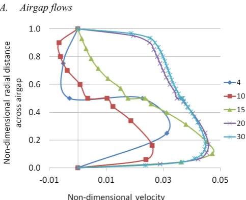
Fig. 4. Velocity profile across airgap, midway along core length, the legend showing the number of cells across the airgap radially, from 4 – 30
Five flow profiles, at equal axial intervals, were extracted along a line located across the airgap radially from the rotor to stator surface. The flow profiles in the airgap in the axially front and back regions do not change significantly with mesh refinement. Increases in radial cell count across the airgap can help to resolve a more defined velocity profile, but the
[image:4.595.307.551.388.560.2]general flow trend is reasonably predicted. This is also true for the flow in the airgap near stator vents. However, where both rotor and stator vents converge on the airgap the flow mixes in the narrow, highly turbulent region, and the solution shows a higher dependency on the mesh.
Figure 4 shows the velocity profile along a radial line through the airgap in this mixing convergent region of the rotor and stator vents with the airgap for meshes with radial cell counts from 4 - 30. In this location, a lower number of cells can be shown to suggest a reversal of flow. This will have an effect on the heat transfer into the airgap, vent flow distribution, windage torque, discussed below.
The data shown in Figure 4 suggests that a radial cell count across the airgap of 20 cells would be sufficient to determine the solution as independent of the mesh.
B. Stator Vent Flow
Stator vent flow behaviour was investigated by looking at the mass flow rate through each vent as well as velocity profiles at a number of locations spanning the axial width of each vent. There are key effects on stator vent flows which are caused as a result of changing the cell count across the stator vent in an axial direction.
Different flow complexities were seen depending on the geometrical features which interacted with each stator vent. Figure 5 shows the two types of stator vent discussed below; stator vent type 1 interacts with the airgap and type 2 interacts with the airgap and adjacent rotor vent.
Fig. 5. Schematic of stator vent interactions with airgap and rotor vents; 2 types discussed in Figure 6 and Figure 7.
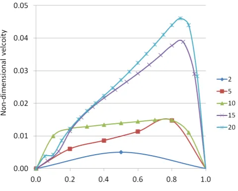
[image:4.595.43.285.455.652.2]peak on the right hand side of the profile. It is not just the change in mass flow, but the skewness of the profile which is significant for heat transfer. Here, the increase in cell count across the stator vent alters the peak velocity in the flow profile to move to the right, as well as increasing in magnitude. The peak velocity will cause the heat transfer coefficient to increase, but perhaps more importantly, the heat transfer on the right-hand-side wall will be significantly higher than the heat transfer coefficient on the left-hand-side wall. This demonstrates the value of CFD modelling, in that no other flow modelling method will detect this imbalance. It also demonstrates the care which must be taken when meshing a CFD case. Heat transfer coefficient correlations are not well suited to interrogating the effects of a skewed profile in a narrow channel.
This skew effect is found to be more pronounced further down the machine core’s axial length due to the development of the flow profile and the stronger rotational flow direction. For instance in the first vent, shown in Figure 7, the flow is simpler compared to figure 6 (located further down the core length), here the flow does not have the additional interactions of rotor vents. For this simpler flow case (figure 7) the mesh density in the stator vent has relatively little effect on the flow profile, unlike the flow shown in figure 6.
Fig. 6. Velocity profile across axial width of individual stator vent located at rotor/stator vent and airgap intersection, for varying axial cell counts 2 - 20
The third effect to note of the impact of the axial cell count across a stator vent is the resolution of the shape of the velocity profile through the vent. This is different from the skewness effects presented in Figure 6. Figure 7 shows how the shape of the profile and the gradient at the wall vary with cell count, even though the profiles are only marginally skewed.
[image:5.595.310.546.60.232.2]One reason for the noteworthy solution dependence of the mesh in the stator vents is due to the slower flow velocities than are found in the airgap and rotor vents. The delicately balanced flow network of airgap and vent paths is more greatly affected in the stator vent regions with weaker flow which compounds inaccuracies in the evaluation of heat transfer coefficients.
Fig. 7. Velocity profile across axial width of first individual stator vent, for varying axial cell counts 2 – 20
C. Rotor Vent Flow
The rotor flow was found to be insensitive to cell count once a reasonable cell count to resolve the flow features was attained. Typically the solution can be deemed mesh independent at 10 cells across the axial width of a rotor vent (see Figure 8).
It is thought that the strong pressure gradient, caused by the rotor pole pumping effect, drives this flow [12]. Mesh insensitivity is due to the strong velocities in the vent causing less chance for recirculation or skewed flows.
Fig. 8. Velocity profile across axial width of individual rotor vent located midway along the group of rotor vents, for varying axial cell counts 2 - 20
D. Secondary effects
There are two other areas of note with respect to the solution dependency on the mesh:
[image:5.595.46.286.333.525.2]changes through the airgap and vents, due to mesh effects, do not impact the much larger stator-casing channel flow.
Secondly, the total windage torque comprising both the viscous and pressure parts was evaluated on all rotating surfaces. The total windage torque was affected by changes in the cell distribution, primarily in the airgap. Mesh changes across the airgap were found to affect the predicted torque by up to 7.5%. Airgap regions are a well understood contributor to windage in an electrical machine due to the narrow gap with high relative velocities of the rotor and stator surfaces and their blended boundary layers. This airgap is particularly sensitive to mesh effects due to the added complexity caused by rotor and stator vent interactions. The windage was also partly affected by the rotor vent density. The rotor vents can affect the torque by up to 3.9%. The stator vent entry region mesh refinement was found to alter the torque by up to 5.8%. However, the stator vent cell refinement across the vent, in an axial direction, did not affect the torque significantly.
IV. CONCLUSION
CFD is a powerful analysis tool for electrical machine engineers. It has the ability to generate vast amounts of airflow and thermal data in a conjugate environment with a higher resolution than alternative solution methodologies. This paper demonstrates that meshing does significantly affect results. Key geometrical regions which require particular meshing effort to achieve a quality solution are highlighted. Cell counts which performed well for this particular vented case are quantified. However, there are no all-encompassing design rules for meshing recommended as mesh requirements are flow and geometry dependent. Instead, the pragmatic approach to meshing presented within this paper is recommended. The key regions where the solution and geometry are likely to increase mesh dependency should be identified and detailed local mesh independency studies must be carried out for confidence in the solution.
It has been shown that changes in meshing alone for a vented, complex machine topology can affect the flow rate in a single vent by up to 55% and heat transfer coefficient by 128%. The windage prediction may also be altered by up to 7.5%. These changes must be viewed in the context of machine design, for which the CFD analysis is carried out. These solution changes, caused solely by mesh manipulations, may be of a similar order as the improvement margins which are being targeted. For this reason, mesh independency studies are fundamental to the CFD process, to ensure that modelling results in physical design improvements, such as efficiency, lifetime manufacturing costs and effects on electromagnetic performance, are achieved.
V. ACKNOWLEDGMENT
Financial support from the EPSRC Impact Acceleration Account, is gratefully acknowledged – grant number EP/K503800/1.
VI. REFERENCES
[1] M. Shanel, "Investigation of Rotor Cooling in Salient Pole Electrical Machines", University of Nottingham, 2002.
[2] M. Schrittwieser, A. Marn, E. Farnleitner, and G. Kastner, "Numerical analysis of heat transfer and flow of stator duct models", International Conference on Electrical Machines (ICEM) Marseille, France: IEEE, 2012, pp. 385-390.
[3] A. Hughes, Electric Motors and Drives, 2006.
[4] P. H. Connor, S. J. Pickering, C. Gerada, C. N. Eastwick, C. Micallef, and C. Tighe, "Computational Fluid Dynamics Modelling of an Entire Synchronous Generator for Improved Thermal Management", IET Electric Power Applications, vol. 7, pp. 231-236, March 2013.
[5] A. Boglietti, A. Cavagnino, D. Staton, M. Shanel, M. Mueller, and C. Mejuto, "Evolution and Modern Approaches for Thermal Analysis of Electrical Machines", IEEE Transactions on Industrial Electronics, vol. 56, pp. 871-882, Mar 2009.
[6] S. S. Borges and C. A. Cezario, CFD and Thermography Techniques Applied in Cooling Systems Designs: In Tech, 2012. [7] C. Micallef, S. J. Pickering, K. A. Simmons, and K. J. Bradley,
"Improved Cooling in the End Region of a Strip-Wound Totally Enclosed Fan-Cooled Induction Electric Machine", IEEE Transactions on Industrial Electronics, vol. 55, pp. 3517-3524, Oct 2008.
[8] B. D. J. Maynes, R. J. Kee, C. E. Tindall, and R. G. Kenny, "Simulation of airflow and heat transfer in small alternators using CFD", IEE Proceedings-Electric Power Applications, vol. 150, pp. 146-152, Mar 2003.
[9] M. Polikarpova, P. Roytta, J. Alexandrova, S. Semken, J. Nerg, and J. Pyrohonen, "Thermal design and analysis of a direct-water cooled direct drive permanent magnet synchronous generator for high-power wind turbine application," in International Conference on Electrical Machines (ICEM) 2012, pp. 1294-1300.
[10] Ansys, Fluent User Manual: Accessed 2014-2016, Versions 15.0-16.2.
[11] H. Versteeg, K and W. Malalasekera, “An Introduction to Computational Fluid Dynamics. The Finite Volume Method”,
second edition, PEARSON Prentice Hall, 2007.
[12] M. Shanel, S. J. Pickering, and D. Lampard, "Conjugate heat transfer analysis of a salient pole rotor in an air cooled synchronous generator," IEEE International Electric Machines and Drives Conference, Vols 1-3, pp. 737-741, 2003.
[13] A. Bejan, Heat Transfer: John Wiley & Sons, Inc, 1993. [14] D. A. Howey, A. S. Holmes, and K. R. Pullen, "Measurement of
stator heat transfer in air-cooled axial flux permanent magnet machines," IECON, 35th Annual Conference of IEEE Industrial Electronics, Vols 1-6, pp. 1114-1119, 2009.
[15] L. Slupik, J. Smolka, and L. C. Wrobel, "Experimentally Validated Numerical Model of Coupled Flow, Thermal and Electromagnetic Problem in Small Power Electric Motor",
Computer Assisted Methods in Engineering and Science, vol. 20, pp. 133-144, 2013.
[16] D. A. Howey, R. N. Childs, and A. S. Holmes, "Air-Gap Convection in Rotating Electrical Machines", IEEE Transactions on Industrial Electronics, vol. 59, pp. 1367-1375, 2012.
[17] M. S. Salim and S. C. Cheah, "Wall y+ Strategy for Dealing with Wall-bounded Turbulent Flows," in International MultiConference of Engineers and Computer Scientists, 2009.
[18] Z. Huang, "Thermal Design of Electrical Machines", in Department of Measurement Technology and Industrial Electrical Engineering Lund: Lund University, 2013.
VII. BIOGRAPHIES
Peter H. Connor received an M.Eng. and Ph.D. from the Department of Mechanical, Materials and Manufacturing Engineering Department, University of Nottingham, UK, in 2009 and 2014 respectively. He is a Research Fellow in the Fluids and Thermal Engineering Research Group and is a member of the Cummins Innovation Centre, both of which are based within the Faculty of Engineering at the University of Nottingham. His research interests include conjugate heat transfer CFD analysis, experimental thermal testing of synchronous generators as well as mechanical design of electrical machines and test facilities.
Carol N. Eastwickreceived her BEng and PhD in Mechanical Engineering in 1990 and 1995 respectively. She is currently an Associate Professor in the Faculty of Engineering at the University of Nottingham, having worked on modelling and experimental investigations of thermofluids associated with rotating machinery for nearly twenty years.
Stephen J. Pickering received the B.Sc. and Ph.D. degrees in mechanical engineering from the University of Nottingham, Nottingham, U.K., in 1979 and 1984, respectively. He joined the University of Nottingham as a lecturer in 1988, where he is currently Hives Professor of Mechanical Engineering in the Faculty of Engineering. He has extensive research experience in thermo-fluids and has undertaken research into the cooling of electric machines for over twenty years.
Chris Gerada received the Ph.D. degree in numerical modeling of electrical machines from The University of Nottingham, Nottingham, U.K., in 2005. He subsequently worked as a Researcher with The University of Nottingham on high-performance electrical drives and on the design and modeling of electromagnetic actuators for aerospace applications. In 2008, he was appointed as a Lecturer in electrical machines; in 2011, as an Associate Professor; and in 2013, as a Professor at The University of Nottingham. His main research interests include the design and modeling of high-performance electric drives and machines. Prof. Gerada serves as an Associate Editor for the IEEE TRANSACTIONS ON INDUSTRY APPLICATIONS and is the Chair of the IEEE IES Electrical Machines Committee.