A new Constant Pushing Force Device for human walking
analysis
LENZO, Basilio <http://orcid.org/0000-0002-8520-7953>, ZANOTTO,
Damiano, VASHISTA, Vineet, FRISOLI, Antonio and AGRAWAL, Sunil
Available from Sheffield Hallam University Research Archive (SHURA) at:
http://shura.shu.ac.uk/13977/
This document is the author deposited version. You are advised to consult the
publisher's version if you wish to cite from it.
Published version
LENZO, Basilio, ZANOTTO, Damiano, VASHISTA, Vineet, FRISOLI, Antonio and
AGRAWAL, Sunil (2014). A new Constant Pushing Force Device for human walking
analysis. In: 2014 IEEE International Conference on Robotics & Automation (ICRA).
IEEE, 6174-6179.
Copyright and re-use policy
See
http://shura.shu.ac.uk/information.html
Sheffield Hallam University Research Archive
A New Constant Pushing Force Device for Human Walking Analysis
Basilio Lenzo,
Student Member, IEEE
, Damiano Zanotto,
Member, IEEE
,
Vineet Vashista,
Student Member, IEEE
, Antonio Frisoli,
Member, IEEE
and Sunil Agrawal,
Member, IEEE
Abstract— Walking mechanics has been studied for a long time, being essentially simple but nevertheless including quite tricky aspects. During walking, muscular forces are needed to support body weight and accelerate the body, thereby requiring a metabolic demand. In this paper, a new Constant Pushing Force Device (CPFD) is presented. Based on a novel actuation concept, the device is totally passive and is used to apply a constant force to the pelvis of a subject walking on a treadmill. The device is a serial manipulator featuring springs that provide gravity balancing to the device and exert a constant force regardless of the pelvis motion during walking. This is obtained using only two extension springs and no auxiliary links, unlike existing designs. A first experiment was carried out on a healthy subject to experimentally validate the device and assess the effect of the external force on gait kinematics and timing. Results show that the device was capable of exerting an approximately constant pushing force, whose action affected subject’s cadence and the motion of the hip and ankle joints.
I. INTRODUCTION
The metabolic cost of walking is determined by mechan-ical tasks such as generating force to support body weight, performing work to redirect and accelerate the center of mass from step to step, swinging the limbs, and maintaining stability. Several works have been carried out in order to provide detailed and meaningful analysis on metabolic cost, often making use of external devices which apply some constraints and/or some forces to a walking person. The metabolic cost of plantar flexor muscletendon mechanical work during human walking was examined in [1] using a robotic ankle exoskeleton on both legs. More in detail, the roles of each ankle plantar flexor muscle in providing body support and forward propulsion during human walking were analyzed in [2] carrying out experiments using a harness worn by subjects walking on a treadmill. The metabolic cost and muscular actions required for the initiation and propagation of leg swing were investigated in [3], and the effects of a horizontal propulsive force on the reduction in metabolic cost during normal walking were studied in [4]. Both in [3] and [4] forces were applied using a rubber tubing stretched over low-friction pulleys with a hand winch.
The application of external constraints and/or applied forces during walking can lead to changes in human motion. Moreover, added weight and inertia can influence human
1Basilio Lenzo and Antonio Frisoli are with PercRo Laboratory,
TeCIP Institute, Scuola Superiore Sant’Anna, Pisa, Italy
[email protected], [email protected]
2Damiano Zanotto, Vineet Vashista and Sunil Agrawal are with
the ROAR Laboratory, Columbia University, New York City, USA
[email protected], [email protected], [email protected]
motion as well. Hence, it is important to quantitatively esti-mate their effect. A novel tethered pelvic assist device was used in [5] to study motor adaptation in human walking with externally applied forces on the pelvis, with no added mass and inertia. As the system was passive, the applied force was configuration dependent. Influencing human motion is desirable in some cases, as in the motor rehabilitation of stroke survivors. Effects obtained from treadmill training with force perturbations on overground walking in patients with incomplete spinal cord injury were investigated in [6]. Many examples of robotic gait trainers for motor rehabilita-tion of neurologically impaired subjects have been developed in the past, such as the Lokomat [7], the ALEX I, II and III [8], [9], [10], the LOPES [11] and the SPARKy [12].
In this paper, the design of a new Constant Pushing Force Device (CPFD) is presented. It consists of a passive serial manipulator exploiting a novel actuating technique based on extended gravity balancing techniques using springs [13], which makes the device extremely simple and lightweight. It was designed to analyze the effect of a constant horizontal force, pushing the pelvis of a subject walking on a treadmill, in terms of gait adaptation. The exerted force is easily adjustable and is theoretically constant regardless of the configuration of the manipulator, which is gravity balanced at the same time.
The paper is organized as follows. In Section II, gravity balancing principles are described, and the idea of actuation derived by such technique is presented. Section III deals with the design of the new device - after stating the de-sign requirements, some possible dede-signs are investigated, thereafter, the chosen system is optimized according to the defined criteria. In Section IV, results from a first experiment aimed to experimentally validate the design are presented, then final conclusions and future perspectives are discussed in Section V.
II. GRAVITY BALANCING AND ACTUATING IDEA
A machine is said to be gravity balanced if no joint actuator inputs are needed to keep the system in equilibrium in any configuration, i.e., the potential energy of the device is invariant. Theoretically, this happens if the centre of mass of the machine is inertially fixed, or if some elastic elements suitably compensate for the variations of the potential energy due to changes of configuration (motion of masses). Several methods of gravity balancing have been proposed over the years, exploiting clever designs that utilize counterweights, springs, cams, auxiliary links [14], [15], [16], [17].
2014 IEEE International Conference on Robotics & Automation (ICRA) Hong Kong Convention and Exhibition Center
Let us consider a weightless link (Fig. 1(a)) whose length isl, which can rotate about pointO, having an attached mass m at the free extremity. Its configuration is defined by the angleθ, so it has1degree of freedom (dof). This system can
be balanced using a zero free length spring whose extremities are connected to the link at pointQ(located at a distanceb fromO) and to the fixed frame at pointP, which is vertically aligned withO and whose distance from O isa.
(a)
P
θ
A θ
δ
(b)
b l a
m O
Q
θ1
2 B
C
m1 m2
h1
l1
h2 l2
Fig. 1. Single link configuration (a) and 2-dof architecture (b).
The total potential energyE of the system isE=Em+ Es=mglcosθ+12kδ2, whereEmis the contribution of the mass (gbeing the gravity acceleration) andEsis the contri-bution of the spring having lengthδ=√a2+b2−2abcosθ.
To ensure the equilibrium for any configuration we set ∂E ∂θ =
0∀θ, thus for fixedm,l,aandb, the system can be exactly balanced using a zero free length spring having stiffness k= mglab . The principle of gravity balancing described above
was extended in [13] as a concept of actuation for serial manipulators with any kinematics. In this work, we exploit this idea by defining an additional potential energy term associated to a constant (and therefore conservative) force which a manipulator is requested to exert at the end point. Again, the total potential energy of the system is made to be constant regardless of the system’s configuration. Details on how to apply this method for a specific design problem are presented in the following section.
III. DESIGN OF THE NEW DEVICE
A. Device specifications
The device has to apply a desired pushing force to a subject walking on a treadmill. On one side, the device is connected to a fixed frame. The end point of the device is interfaced with the user, which was chosen to be located at the pelvis. Indeed, the motion of the pelvis has an important role in gait as it assists forward propulsion of the body by transferring forces from the lower extremity to the trunk. It is also crucial in assisting swing initiation and in modulating the vertical displacement of the body center of mass, helping to reduce energy consumption during walking [18], [19].
While walking, the human pelvis has a general 3D motion with nonzero components in all the three spatial directions [20]. The kinematics of the device must therefore be able to follow such general spatial motion. Lastly, it is desirable to design a gravity balanced device, so that no additional weight is added to the walking subject.
B. Design solutions
The device was chosen to be a serial manipulator. In order to be able to follow the 3D translational motion of the attachment point on the pelvis, the device needsn≥3
dof. For the sake of simplicity, we set n = 3 and the
axis of the first joint was chosen to be vertical (directed as gravity), and the remaining part was chosen to be a planar mechanism. Thus, the following analysis will be related to planar 2-dof mechanisms architectures. A spherical joint was mounted at the interface between user and device, to allow the transmission of pure forces to the human pelvis.
3
G
2
k1
k2
A
B
C D
E
m1 m2
a1
b1
a
b2 k F
3
a
k4
b3
a4
b4
A
B
C F
(a) (b)
Fig. 2. Architecture 1: gravity balanced (a) and exertingF (b).
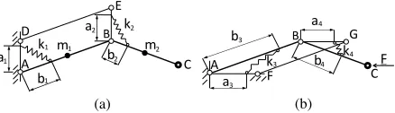
1) Architecture 1: The first architecture analyzed is
de-picted in Fig. 1(b). The directions of links 1 and 2 are
represented by unit vectors ~x1 and x~2, while ~y is a unit
vector whose direction is opposite to gravity. Each link has lengthli and massmi, and the position of its center of mass is indicated byhi.
The design goals of exerting the desired force and bal-ancing gravity can be addressed separately, and the results can be superimposed. In Fig. 2(a) some links and hinges are added to form the parallelogram linkage ABDE. Two zero free-length springs having stiffnesskiand lengthδi are added, each one being the third side of a triangle having sidesai directed as~y (due to the parallelogram linkage), bi directed as linki, and the springki(i= 1,2). The potential energy related to the masses is
Em=−m1P~1·~g−m2P~2·~g, (1)
whereP~1=h1x~1,P~2=l1x~1+h2x~2. Also,~g=−g~y, so
Em=m1h1~y·x~1+m2l1~y·x~1+m2h2~y·x~2. (2)
The potential energy related to the springs is
Es= 12k1δ21+12k2δ 2
2, (3)
where δ2
i = a2i +b2i −2aibi~y·x~i. Therefore, the total potential energy is
Em+Es=C+ (m1h1+m2l1−k1a1b1)~y·x~1+
(m2h2−k2a2b2)~y·x~2, (4)
whereCis a constant term. Then, in order to have ∂θ∂E
i = 0
∀θi, it must be k1 = m1ha1+m2l1
1b1 and k2 =
m2h2
a2b2. If such
conditions are satisfied, the mechanism is gravity balanced. In Fig. 2(b) some links and hinges are added to the original mechanism (which is now considered massless), as to form
[image:3.612.80.275.161.270.2] [image:3.612.327.546.199.262.2]the parallelogram linkage ABFG. As before, two zero free-length springs having stiffness ki and length δi are added, each one being the third side of a triangle having sides ai directed as~y (due to the parallelogram linkage),bi directed as link i, and the spring ki (i = 3,4). Unlike the previous design, there is no gravitational potential energy. However, in this subcase we would like to exert a horizontal force
~
F to push the user attached to the end effector. According to the third principle of dynamics, the mechanism would then be subjected to a force pushing it back, as shown in Fig. 2(b). Assuming such force to be the same regardless of the configuration, it is possible to define a potential energy associated to F:
Ef =−F~·P ,~ (5)
whereP~ =l1x~1+l2x~2 andF~ =−F ~x, so
Ef =F l1~x·x~1+F l2~x·x~2. (6)
As for the springs, Eq. 3 still holds, but now δi2 =a2i +
b2i −2aibix~i·~x, thereby the total potential energy is
Ef+Es=C0+ (F l1−k1a1b1)~x·x~1+ (F l2−k2a2b2)~x·x~2, (7)
where C0 is a constant term. To ensure ∂E
∂θi = 0 ∀θi it
must be k1= aF l1b11 andk2=aF l2b22.
In line of principle, the two design goals of gravity balancing the mechanism and exerting the desired force can be obtained by superimposing the two configuration described above. However, the design would be complex and bulky since there would be several springs and auxiliary links, as well as interference problems.
1
a
2
l1 l2
k2
a2
k3
b3
a3
b2
m1
m h1
h2 l1
l2
k2 2
k3
b3
a3
b2
m2
h1
h2
k2
a1
b1
F
(a) (b)
[image:4.612.57.302.463.529.2]m
Fig. 3. Architecture 2: gravity balanced only (a) and gravity balanced exertingF (b).
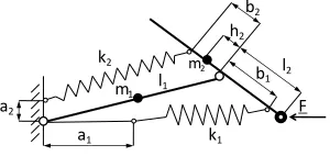
2) Architecture 2: A novel design to obtain gravity
bal-ancing without auxiliary links was proposed in [21]. Fig. 3(a) shows the architecture of this mechanism, where link 1 is
prolonged over the hinge connecting link2, zero free-length
spring2is connected from the frame to link2and zero
free-length spring 3 is connected between links1 and2. Again,
writing the potential energies involved and requiring the total potential energy to be constant, the following conditions must hold:
m1gh1+m2gl1=k2a2l1 (8)
m2gh2=k2a2b2 (9)
−k2l1b2+k3a3b3= 0. (10)
As in architecture 1, this kind of design can be slightly
changed and adapted to the case of exerting a horizontal force at the end effector, this time by makinga1 horizontal
rather than vertical. Furthermore, the two configurations can be superimposed to obtain a gravity balanced mechanism that exerts the desired force (Fig. 3(b)). In particular, the two springs connected between link1and link2can be reduced
to one spring. The advantage of this architecture with respect to the architecture1is the ease of design, due to the reduced
numbers of links and springs. In this case the conditions to be satisfied are (8), (9) and
F l1=k1a1l1 (11)
F l2=k1a1b1 (12)
−k1l1b1−k2l1b2+k3a3b3= 0. (13)
3) Implemented architecture: By looking at (8), (9), (11),
(12) and (13) one can notice that the contribution of springk3
appears only in (13), and apparentlyk3seems to be essential
since all the quantities involved are positive and ifk3 = 0
then (13) could not be satisfied. However,b2could be set to
a negative value: physically, this means that the attachment point of springk2 on link2 isb2 far from the hinge, in the
direction opposite to the end-effector, as shown in Fig. 4. By imposingb2<0, from (9) we get the constrainth2<0:
physically, this means that the centre of mass of link2 lays
on the other side of the hinge as well.
The implemented architecture is shown in Fig. 4. It is grav-ity balanced and it exerts the desired force regardless of its configuration. This goal is achieved without auxiliary links and by using only 2 springs, thus it is a completely novel design. The magnitude of the force F is easily adjustable, since from (11) and (12) it is proportional toa1.
l1
l2
F k1
a1
k2
a2
b2
m1
m2
h2
b1
Fig. 4. Architecture gravity balanced and exertingFwith2springs only.
C. Approximate spring design solution
The CPFD is represented in Fig. 5. For simplicity, it was decided not to mount any spring on the most proximal joint. As a result, the gravitational potential is unchanged, while the force exerted will lay on the plane defined by the first joint. This is acceptable as long as the first joint range of motion is very small (it was verified experimentally).
[image:4.612.361.511.469.540.2]means of a cable-pulleys system and a traditional nonzero free length spring. This solution might be bulky and complex since in addition to cables and pulleys, a large amount of space is required for the storage of the nonzero free-length spring, which cannot be physically located between the theoretical attachment points. On the other hand, non-zero free length springs can be mounted in the same locations of the zero free-length springs, as studied in [23]. In such case, the equations to be satisfied become
m1gh1+m2gl1=k2(1−√ l02
a2
2+b22+l21
)a2l1 (14)
m2gh2=k2(1−√ l02
a2
2+b22+l21
)a2b2 (15)
F l1=k1(1−√ l01
a2
1+b21+l21
)a1l1 (16)
F l2=k1(1−√ l01
a2
1+b21+l21
)a1b1 (17)
−k1b1(1−√ l01
a2
1+b21+l21
)−k2b2(1−√ l02
a2
2+b22+l21
) = 0, (18)
where l01 and l02 are the free length of springs k1
and k2. It might be proven that (14)-(18) yield acceptable
approximations if the following conditions hold:
2b1l1x~1·x~2−2a1l1x~1·~x−2a1b1x~2·~x
a2
1+b21+l21
<<1 (19)
−2l1b2x~1·x~2−a2l1~y·x~1+2a2b2~y·x~2
a2
2+b22+l21
<<1. (20)
F
Fig. 5. Constant Pushing Force Device.
For the sake of simplicity, non zero free-length springs were chosen for the first prototype of the device. Due to the limited motion of the pelvis during walking, the device was optimized in the neighborood of a representative configuration as described in the following.
D. Modelling and Optimization
A standard pelvis motion over the gait cycle [20] was considered as the input for the optimization process. Joint angles and their time derivatives were calculated by means of inverse kinematics. Then the forces at the end effector were calculated with an inverse dynamic model of the device.
The target design force was set to Fx = 50 N, Fy = Fz= 0N (axes as in Fig. 5). The actual force output from the dynamic model is not expected to exactly match the one predicted by the static model (14)-(18) because:
• the static model does not take into account the proximal
dof (rotation about vertical axis);
• the static model does not account for dynamic forces;
• the static model (featuring non zero free-length springs)
is approximate.
However, since the number of free parameters (lengths of the links, springs attachment points, center of mass of link
2, etc.) is larger than the number of constraints (14)-(18),
the best geometry of the mechanism was defined through a numerical optimization. The used cost function, defined over the representative gait cycle, is|mean(Fx−50)|+std(Fx). A maximum allowed value of5N is set forFy andFz, and structural resistance of the springs is also imposed.
The optimum design parameters are (Fig. 4):l1= 0.971
m,l2= 0.177m,a1= 0.218m,a2= 0.242m,b2=−0.24
m, h2 =−0.266 m, from which spring ratios and lengths
are derived. It was observed that the errors due to use of nonzero free length springs could partially compensate the errors due to inertia and to the movements of the first joint.
IV. EXPERIMENTAL VALIDATION
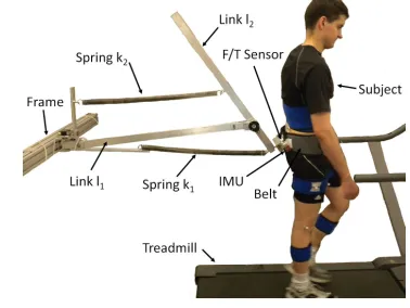
A. Hardware implementation
Fig. 6. First prototype of CPFD.
Based on the design optimization presented above, a first prototype of CPFD was fabricated and assembled at Columbia University (Fig. 6). The device is made out of light-weight aluminum bars. Eyebolts located on the bars allow fast connection of the springs. The length a1 can
be adjusted by moving the corresponding eyebolt along a discrete set of positions, thus making it possible to adjust the nominal force Fx. Incremental encoders (Kubler T8.582x series, 18400 pulse rate) are mounted at each joint. The
interface with the subject consists of a semi-rigid pelvic belt (OspreyIsoF orm CM Hipbelt) connected to the end point of the device by means of a spherical joint. A force/torque sensor (ATI M ini−45) is installed on a bracket located
between the spherical joint and the belt to record interaction forces. An inertial measurement unit (IM U) rigidly attached to the mounting bracket of the force sensor allows to estimate the orientation of the latter with respect to a fixed frame.
B. Protocol
As a proof-of-concept validation of our approach, a first experiment was conducted on a single male subject (age30
years, h= 1.80m, w= 68kg). The experiment consisted of three sessions, each one lasting 5 minutes. In the first
and in the last sessions (baseline and post-test, respectively)
[image:5.612.337.526.272.414.2] [image:5.612.81.300.333.451.2]the subject performed free treadmill stepping at a constant speed (1 m/s). In the second session (training), the device was adjusted to exert a force of 50 N on the subject’s pelvis. Reflective markers were placed on the human body to measure gait kinematics (VICONBonitaB3), following the
arrangement suggested in [24]. During the training session, data from the encoders, the force/torque sensor and the inertial sensor were recorded through aDS1103board (f s= 200 Hz for the IM U, f s = 1 kHz for other signals). Motion capture data were sampled at 100 Hz during all the sessions. Synchronization between the two systems was achieved through a dedicatedT T Lsignal.
Only the data recorded over the last minute of each session were retained for subsequent analysis. Each signal was split into gait cycles, and single-stride profiles were time-normalized (0-100% of the gait cycle) and subsequently
averaged across all the steps.
C. Results
co
s(
θx1
)
−1 0 1
co
s(
θy1
)
−1 0 1
% of stride
co
s(
θz1
)
0 20 40 60 80 100
−1 0 1
|F
|
[N
]
0 20 40 60 80
Fig. 7. Magnitude and direction cosines of the interaction force.
Fig. 7 shows the magnitude of the interaction force over the gait cycle (GC), where 0 and 100% indicate the initial
contact of the right leg (heel strike). The average value of the force was 42.01 N (RMS), less than the nominal desired value of 50 N. Force peaks were recorded at 15%
and 65%GC, corresponding to the beginning of the right
and left single support phases, respectively. The direction cosines with respect to x1,y1 andz1 are also portrayed in
Fig. 7. As expected, the largest projection of the force vector lies alongx1 and its negative value indicates that the device
actually exerted a forward force on the subject. The out-of plane component of the force (i.e., the projection alongy1)
is negligible, whereas the projection alongz1 indicates that
the exerted force pointed downward.
The offset in the desired average force can be explained with the average configuration of the device not matching the nominal one when the subject was walking. Indeed, design
−0.05 0 0.05
−60 −40 −20 0 20
∆ x (m)
F (N)
−0.05 0 0.05
−60 −40 −20 0 20
∆ z (m)
F (N)
Fx Fy Fz
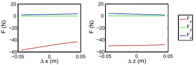
Fig. 8. Exerted force variations with configuration changes.
optimization was carried out by assuming that the device operates in the neighborhood of a nominal configuration. Due to the approximate implementation of our design approach (i.e., one with non zero-length springs), the exerted force slightly varies when this average configuration changes. Fig. 8 illustrates how the average force projections are expected to change as a function of the offsets ∆x and
∆z from the nominal position: a positive ∆x reduces Fx and increases the downward force (positiveFz). Therefore, experimental data suggest that the subject’s pelvis was too far away from the inertial frame, presumably5cmfurther than the nominal configuration (Fig. 8, left plot). To prevent this problem in future tests, augmented visual/auditory feedback will be provided to the subject to guarantee that the position of his/her pelvis along x will remain in an appropriate neighborhood of the nominal configuration.
Kinematic data showed a slight reduction in the hip flexion/extension range of motion (ROM) when subject wore the device (baseline: 38.0±1.2 deg, training: 33.3 ±1.4
deg). This was related to a reduction in the stride length, that also reflected in a slight decrease in the stride time (baseline:1.36±0.02s, training:1.30±0.03s), the walking speed being constant. No noticeable changes were measured at the knee joint. Conversely, we observed an increase in the ankle peak plantarflexion (Fig. 9) during weight acceptance (baseline:−11.6±4.7 deg, training:−15.7±3.1 deg) and a slight decrease of dorsiflexion prior to push-off (base-line:10.6±2.3deg, training:9.2±0.7deg). No noticeable changes were observed in the post-test session, indicating that any motor adaptation was washed out by the5-th minute
of the post-test.
0 20 40 60 80 100
−20 −15 −10 −5 0 5 10 15
θAN
KL
E
[d
e
g
]
% of stride
Baseline CPFD Post
Fig. 9. Ankle angle during baseline, training and post-training.
[image:6.612.338.533.50.115.2] [image:6.612.100.246.288.488.2] [image:6.612.350.518.546.625.2](namely, at the body center of mass) which tends to push the subject forward. Downhill walking has been shown to reduce efforts of the ankle plantar flexor at push-off (positive work), and increases the activity of the knee extensors, which stabilize the knee at heel strike [28] (negative work), the overall effect being a decrease in metabolic cost of walking, at least within a certain range of grades [29]. Therefore, even though further experiments needs to be conducted on a larger sample size (by, e.g., measuring subject’s muscle activity and metabolic cost), there is the possibility that utilizing the CPFD could actually reduce metabolic cost of walking.
V. CONCLUSION
The design of a new Constant Pushing Force Device for human walking analysis was presented. The device is based on a novel actuating technique derived from gravity balancing theory, and it allows to exert a desired constant force at the pelvis of a subject walking on a treadmill.
Unlike previous designs, our approach allows us to utilize the same pair of springs to achieve two goals simulta-neously: gravity compensation and exertion of a constant pushing force. It is worthwile saying that the step from balancing to actuating is not immediate: there are some mathematical conditions to satisfy to ensure that the force exerted is the desired one. However, such details are currently being investigated and are not included in this paper.
Experimental results show that the device was capable of exerting a pushing force that approximated the nominal prescribed force in magnitude and direction, the deviations being mainly due to the subject walking too far away from the nominal configuration of the CPFD. Observing the analo-gies between subject’s motor adaptations, and those typical of downhill walking, we speculated about the potential for this device to reduce metabolic cost of walking. Future work will experimentally validate this hypothesis on a larger sample size, measuring electromyographic activity on critical muscles of the leg and metabolic cost of walking in addition to the kinematic and kinetic variables analyzed in this study.
REFERENCES
[1] G. S. Sawicki and D. P. Ferris, “Powered ankle exoskeletons reveal the metabolic cost of plantar flexor mechanical work during walking with longer steps at constant step frequency,”Journal of Experimental Biology, vol. 212, no. 1, pp. 21–31, 2009.
[2] C. P. McGowan, R. R. Neptune, and R. Kram, “Independent effects of weight and mass on plantar flexor activity during walking: implications for their contributions to body support and forward propulsion,” Journal of applied physiology, vol. 105, no. 2, pp. 486–494, 2008. [3] J. S. Gottschall and R. Kram, “Energy cost and muscular activity
required for leg swing during walking,”Journal of Applied Physiology, vol. 99, no. 1, pp. 23–30, 2005.
[4] ——, “Energy cost and muscular activity required for propulsion during walking,” Journal of Applied Physiology, vol. 94, no. 5, pp. 1766–1772, 2003.
[5] V. Vashista et al., “Force adaptation in human walking with sym-metrically applied downward forces on the pelvis,” in Engineering in Medicine and Biology Society (EMBC), 2012 Annual International Conference of the IEEE. IEEE, 2012, pp. 3312–3315.
[6] S.-C. Yenet al., “Locomotor adaptation to resistance during treadmill training transfers to overground walking in human sci,”Experimental brain research, vol. 216, no. 3, pp. 473–482, 2012.
[7] G. Colombo, M. Wirz, V. Dietz et al., “Driven gait orthosis for improvement of locomotor training in paraplegic patients,” Spinal Cord, vol. 39, no. 5, pp. 252–255, 2001.
[8] S. K. Banala, S. H. Kim, S. K. Agrawal, and J. P. Scholz, “Robot as-sisted gait training with active leg exoskeleton (alex),”Neural Systems and Rehabilitation Engineering, IEEE Transactions on, vol. 17, no. 1, pp. 2–8, 2009.
[9] K. N. Winfree, P. Stegall, and S. K. Agrawal, “Design of a minimally constraining, passively supported gait training exoskeleton: Alex ii,” inRehabilitation Robotics (ICORR), 2011 IEEE International Confer-ence on. IEEE, 2011, pp. 1–6.
[10] D. Zanotto, P. Stegall, and S. K. Agrawal, “ALEX III: A novel robotic platform with 12 DOFs for human gait training,” inProc. of the IEEE International Conference on Robotics and Automation, ICRA 2013, 2013, pMID: not available.
[11] E. Van Asseldonket al., “Selective control of a subtask of walking in a robotic gait trainer (lopes),” in Rehabilitation Robotics, 2007. ICORR 2007. IEEE 10th International Conference on. IEEE, 2007, pp. 841–848.
[12] T. G. Sugar, K. W. Hollander, and J. K. Hitt, “Walking with springs,” in SPIE Smart Structures and Materials+ Nondestructive Evaluation and Health Monitoring. International Society for Optics and Photonics, 2011, pp. 797 602–797 602.
[13] B. Lenzo, A. Frisoli, F. Salsedo, and M. Bergamasco, “An innovative actuation concept for a new hybrid robotic system,”Romansy 19-Robot Design, Dynamics and Control, p. 135, 2013.
[14] V. Haywardet al., “Freedom-7: A high fidelity seven axis haptic device with application to surgical training,” Experimental Robotics V, pp. 443–456, 1998.
[15] N. Ulrich and V. Kumar, “Passive mechanical gravity compensation for robot manipulators,” inRobotics and Automation, 1991. Proceedings., 1991 IEEE International Conference on. IEEE, 1991, pp. 1536–1541. [16] S. K. Agrawal, G. Gardner, and S. Pledgie, “Design and fabrication of an active gravity balanced planar mechanism using auxiliary parallel-ograms,”Journal of mechanical design, vol. 123, no. 4, pp. 525–528, 2001.
[17] K. Koser, “A cam mechanism for gravity-balancing,” Mechanics Research Communications, vol. 36, no. 4, pp. 523–530, 2009. [18] J. Perry, J. R. Davidset al., “Gait analysis: normal and pathological
function,”Journal of Pediatric Orthopaedics, vol. 12, no. 6, p. 815, 1992.
[19] R. R. Neptune, S. Kautz, and F. Zajac, “Contributions of the individual ankle plantar flexors to support, forward progression and swing initiation during walking,”Journal of biomechanics, vol. 34, no. 11, pp. 1387–1398, 2001.
[20] L. Zhao, L. Zhang, L. Wang, and J. Wang, “Three-dimensional motion of the pelvis during human walking,” inMechatronics and Automation, 2005 IEEE International Conference, vol. 1. IEEE, 2005, pp. 335– 339.
[21] P.-Y. Lin, W.-B. Shieh, and D.-Z. Chen, “A theoretical study of weight-balanced mechanisms for design of spring assistive mobile arm support (mas),”Mechanism and Machine Theory, vol. 61, pp. 156–167, 2013. [22] R. Barentset al., “Spring-to-spring balancing as energy-free
adjust-ment method in gravity equilibrators.” ASME, 2009.
[23] A. Agrawal and S. K. Agrawal, “Design of gravity balancing leg orthosis using non-zero free length springs,”Mechanism and machine theory, vol. 40, no. 6, pp. 693–709, 2005.
[24] M. P. Kadaba, H. Ramakrishnan, and M. Wootten, “Measurement of lower extremity kinematics during level walking,” Journal of Orthopaedic Research, vol. 8, no. 3, pp. 383–392, 1990.
[25] A. Leroux, J. Fung, and H. Barbeau, “Postural adaptation to walking on inclined surfaces: I. normal strategies,”Gait & posture, vol. 15, no. 1, pp. 64–74, 2002.
[26] J. SUN, M. WALTERS, N. SVENSSON, and D. LLOYD, “The influence of surface slope on human gait characteristics: a study of urban pedestrians walking on an inclined surface,” Ergonomics, vol. 39, no. 4, pp. 677–692, 1996.
[27] J. Wall, J. Nottrodt, and J. Charteris, “The effects of uphill and downhill walking on pelvic oscillations in the transverse plane,” Ergonomics, vol. 24, no. 10, pp. 807–816, 1981.
[28] M. Kuster, S. Sakurai, and G. Wood, “Kinematic and kinetic compar-ison of downhill and level walking,”Clinical Biomechanics, vol. 10, no. 2, pp. 79–84, 1995.
[29] D. Wanta, F. Nagle, and P. Webb, “Metabolic response to graded downhill walking.” Medicine and science in sports and exercise, vol. 25, no. 1, p. 159, 1993.