SPARC/CPU-54
Reference Guide
The information in this publication is subject to change without notice. Force Computers, GmbH reserves the right to make changes without notice to this, or any of its products, to improve reliability, performance, or design.
Force Computers, GmbH shall not be liable for technical or editorial errors or omissions contained herein, nor for indirect, special, incidental, or consequential damages resulting from the furnishing, performance, or use of this material. This information is pro-vided “as is” and Force Computers, GmbH expressly disclaims any and all warranties, express, implied, statutory, or otherwise, including without limitation, any express, statutory, or implied warranty of merchantability, fitness for a particular purpose, or non-infringement.
This publication contains information protected by copyright. This publication shall not be reproduced, transmitted, or stored in a retrieval system, nor its contents used for any purpose, without the prior written consent of Force Computers, GmbH.
Force Computers, GmbH assumes no responsibility for the use of any circuitry other than circuitry that is part of a product of Force Computers, GmbH. Force Computers, GmbH does not convey to the purchaser of the product described herein any license under the patent rights of Force Computers, GmbH nor the rights of others.
Copyright 2003 by Force Computers, GmbH. All rights reserved.
The Force logo is a trademark of Force Computers, GmbH. SENTINEL is a registered trademark of Force Computers, GmbH
IEEE is a registered trademark of the Institute for Electrical and Electronics Engineers, Inc.
PICMG, CompactPCI, and the CompactPCI logo are registered trademarks and the PICMG logo is a trademark of the PCI Indus-trial Computer Manufacturer’s Group.
MS-DOS, Windows95, Windows98, Windows2000 and Windows NT are registered trademarks and the logos are a trademark of the Microsoft Corporation.
Intel and Pentium are registered trademarks and the Intel logo is a trademark of the Intel Corporation.
SPARC is a registered trademark, the SPARC logo is a trademark and UltraSPARC is a registered trademark of SPARC Interna-tional, Inc.
PowerPC is a registered trademark and the PowerPC logo is a trademark of International Business Machines Corporation. AltiVec is a registered trademark and the AltiVec logo is a trademark of Motorola, Inc.
Sun, Sun Microsystems, the Sun logo, SPARCengine Ultra, Solaris, Open Boot, SunVTS are trademarks or registered trademarks of SUN Microsystems, Inc.
The Linux Kernel is Copyright Linus B. Torvalds under the terms of the General Public License (GPL).
GoAhead ia a registered trademark of GoAhead Software, Inc. and SelfReliant and Self Availability are trademarks of GoAhead Software, Inc.
LynxOS and BlueCat are registered trademarks of LynuxWorks, Inc.
Tornado, VxWorks, Wind, WindNavigator, Wind River Systems, Wind River Systems and design, WindView, WinRouter and Xmath are registered trademarks or service marks of Wind River Systems, Inc.
Envoy, the Tornado logo, Wind River, and Zinc are trademarks or service marks of Wind River Systems, Inc. Sony is a registered trademark of Sony Corporation, Japan
Ethernet is a trademark and Xerox is a registered trademark of Xerox Corporation
220991 420 000 AA
World Wide Web: www.fci.com
24-hour access to on-line manuals, driver updates, and application notes is provided via SMART, our SolutionsPLUS customer support program that provides current technical and services information.
Headquarters
The Americas
Europe
Asia
Force Computers Inc. 4211 Starboard Drive Fremont, CA 94538 U.S.A.
Tel.: +1 (510) 445-6000 Fax: +1 (510) 445-5301 Email: [email protected]
Force Computers GmbH Lilienthalstr. 15
D-85579 Neubiberg/München Germany
Tel.: +49 (89) 608 14-0 Fax: +49 (89) 609 77 93 Email: [email protected]
Force Computers Japan KK Shibadaimon MF Building 4F 2-1-16 Shiba Daimon
Minato-ku, Tokyo 105-0012 Japan
SPARC/CPU-54 v
Contents
Using This Guide
Other Sources of Information
Safety Notes
Sicherheitshinweise
1
Introduction
Features . . . 1-3
CPU . . . 1-4 Memory . . . 1-4 OpenBoot . . . 1-4Block Diagram . . . 1-5
CPU Board Variants . . . 1-6
SPARC/CPU-54 . . . 1-6 SPARC/CPU-54T . . . 1-7Ordering Information . . . 1-9
Product Nomenclature . . . 1-9 Order Numbers . . . 1-102
Installation
Action Plan . . . 2-3
Requirements . . . 2-4
Environmental Requirements . . . 2-4 Power Consumption . . . 2-5 Software Requirements . . . 2-7Hardware and Software Upgrades and Accessories . . . 2-8
Memory Modules . . . 2-8 IO-54 . . . 2-8 SPARC/IOBP-54 . . . 2-9 Solaris Driver Package . . . 2-9Setting the SCSI Termination . . . 2-10
SCSI 1 Termination . . . 2-10 SCSI 2 Termination . . . 2-10Switch Settings . . . 2-12
SPARC/CPU-54 vii
3
Controls, Indicators, and Connectors
Front Panel of the SPARC/CPU-54 . . . 3-3
LEDs . . . 3-4 Keys . . . 3-5 Reset . . . 3-5 Abort . . . 3-5 Mode . . . 3-5 Connectors . . . 3-6 Ethernet . . . 3-6 Serial I/O . . . 3-7 Keyboard/Mouse . . . 3-8 SCSI . . . 3-9On-Board Connectors of the SPARC/CPU-54 . . . 3-10
4
OpenBoot Firmware
Introduction . . . 4-3
CORE . . . 4-3 CORE Workflow . . . 4-5 CORE Commands . . . 4-6 POST . . . 4-6 OpenBoot . . . 4-6 Optional Boot Parameters . . . 4-7 Boot Devices . . . 4-7 OBDIAG . . . 4-10 VxWorks Support . . . 4-13NVRAM Boot Parameters . . . 4-14
Displaying System Information . . . 4-19
Ethernet Address and Host ID . . . 4-19 ID PROM . . . 4-20Resetting the System . . . 4-21
Activating OpenBoot Help . . . 4-22
5
Maps and Registers
Address Map . . . 5-3
Status and Control Register . . . 5-4
User LED Control Registers . . . 5-6
User LED 1 Control Register . . . 5-6 User LED 2 Control Register . . . 5-7Control Register . . . 5-8
Control and Status Register . . . 5-9
Watchdog Timer and Temperature Control Register . . . 5-10
Watchdog Timer and Temperature Control Status Register . . . 5-10 Watchdog Timer Trigger Register . . . 5-11SYSFAIL and ACFAIL Interrupt Control Register . . . 5-12
Reset Status Register . . . 5-13
System Configuration Identification Register . . . 5-14
SPARC/CPU-54 ix
Switch 4 and 5 Status Register . . . 5-17 Switch 800 Status Register . . . 5-18
Timer Register . . . 5-19
Timer Control Register . . . 5-19 Timer Initial Control Register L . . . 5-20 Timer Initial Control Register U . . . 5-20 Timer Counter Status Register L . . . 5-20 Timer Counter Status Register U . . . 5-20RS-422 Control and Status Register . . . 5-21
Ethernet Control and Status Register . . . 5-22
A
Troubleshooting
B
Battery Exchange
Index
SPARC/CPU-54 xi
Tables
Introduction
Table 1 Standard Compliance. . . 1-8 Table 2 Product Nomenclature . . . 1-9 Table 3 Excerpt from the SPARC/CPU-54 Ordering Information for CPU Boards . . . 1-10 Table 4 Excerpt from the SPARC/CPU-54 Ordering Information for Memory Modules . . . . 1-10 Table 5 Excerpt from the SPARC/CPU-54 Ordering Information for Accessories . . . 1-11
Installation
Table 6 Environmental Requirements . . . 2-4 Table 7 Maximum Power Consumption . . . 2-6 Table 8 Maximum Power Consumption with SPARC/MEM-54 Installed . . . 2-6 Table 9 Switch Settings. . . 2-13 Table 10 Customizing Solaris 8 . . . 2-20 Table 11 Required Solaris Package for Solaris 8 . . . 2-20 Table 12 Devices and Their Appropriate Drivers . . . 2-21 Table 13 Hardware Node Assignment . . . 2-22 Table 14 Instance Number Assignment for SPARC/CPU-54 . . . 2-22 Table 15 Flash Segmentation and Write Protection . . . 2-23
Controls, Indicators, and Connectors
OpenBoot Firmware
Table 19 Boot Parameters . . . 4-7 Table 20 Device Alias Definitions for SCSI#1 . . . 4-8 Table 21 Device Alias Definitions for SCSI#2 . . . 4-9 Table 22 Other Device Alias Definitions . . . 4-10 Table 23 OBDIAG Commands . . . 4-12 Table 24 Setting Configuration Parameters . . . 4-14 Table 25 Diagnostic Routines . . . 4-15 Table 26 Commands to Display System Information . . . 4-20
Maps and Registers
SPARC/CPU-54 xiii
Figures
Introduction
Figure 1 Function Blocks . . . 1-3 Figure 2 Block Diagram of the CPU Board . . . 1-5 Figure 3 SPARC/CPU-54 . . . 1-6 Figure 4 SPARC/CPU-54T . . . 1-7
Installation
Figure 5 SCSI Termination Concept of SPARC/CPU-54 and IOBP-54 . . . 2-11 Figure 6 Location of Switches on Board’s Top Side . . . 2-12 Figure 7 Location of Switches on Board’s Bottom Side . . . 2-13
Controls, Indicators, and Connectors
OpenBoot Firmware
SPARC/CPU-54 xv
Using This Guide
This Reference Guide is intended for users qualified in electronics or electri-cal engineering. Users must have a working understanding of Peripheral Component Interconnect (PCI), VMEbus, and telecommunications.
Conventions
Notation Description
1234 All numbers are decimal numbers except when used with the nota-tions described below
0000000016 Typical notation for hexadecimal numbers (digits are 0 through F), e.g. used for addresses and offsets
00002 Same for binary numbers (digits are 0 and 1)
x Generic use of a letter
n Generic use of numbers
n.nn Decimal point indicator is signaled
Bold Character format used to emphasize a word
Courier Character format used for on-screen output
Courier+Bold Character format used to characterize user input
Italics Character format for references, table, and figure descriptions <text> Typical notation used for variables and keys
[text] Typical notation for optional parameters
... Repeated item
.. Ranges
Note:
No danger encountered. Pay attention to important information marked using this layout
Revision History
Order No.
Revision Date Description
212466 AA February 2001 Preliminary Installation Guide
21466 AB May 2001 Corrected “Expansion” page -xxi;
Removed interfaces section in chapter 1; Removed block diagram of I/O board, infor-mation on I/O-board installation, connector pinouts of I/O-board and created separate Installation Guide for I/O-board;
Corrected Eth 1 and Eth 2 in Figure 1 “Func-tion Blocks” page 1-3;
Removed table “Interfaces on the CPU Board” on page 1-4;
Corrected Figure 2 “Block Diagram of the CPU Board” page 1-5;
Corrected power consumption of SMEM board in Table 7 “SPARC/CPU-54 Maxi-mum Power Consumption” page 2-6; Added “Software Requirements” page 2-7; Corrected safety note in “SPARC/IOBP-54” page 2-9;
Corrected switch settings of SW4-1, SW4-2, SW5-2, and SW5-4 in Table 10 “Switch Set-tings” page 2-11;
Added “Solaris Driver Package” page 2-10; Corrected boot flash writing information in “Booting” page 2-16;
Corrected “Installing Solaris” page 2-17; Corrected “Setting the SCSI Termination” page 2-22;
Corrected Figure 6 “SCSI Termination Con-cept of SPARC/CPU-54 and IOBP-54” page 2-24;
SPARC/CPU-54 xvii
212466 AB May 2001 Corrected pinout 19 and 62 in Figure 14
“68-Pin Ultra-Wide SCSI Connector “68-Pinout” page 3-10;
Corrected Table 18 “On-Board Connectors” page 3-11 and Table 19 “P2 Backplane Con-nector Signals” page 3-11;
Corrected pinout row Z in Figure 15 “P2 VMEbus Connector Pinout Rows Z-B” page 3-12 and row D in Figure 16 “P2 VME-bus Connector Pinout Continued Rows C+D” page 3-13;
Corrected “CORE” page 4-3;
Corrected introduction to CORE commands in “CORE Commands” page 4-6;
Corrected screen shot in “Boot Devices” page 4-7;
Added “POST” page 4-6; Added the “OBDIAG” page 4-10;
Corrected “Diagnostics” page 4-15; Editorial changes
212466 AC June 2001 Corrected SW4-3 and SW4-4 in Table 10
“Switch Settings” page 2-11;
212466 AD July 2001 Added information on VxWorks in
“VxWorks Support” page 4-13;
Added information on PCI Control Register on page 4-18;
212466 AE August 2001 Added the “Sicherheitshinweise” chapter
212466 AF September 2001 Revised “Safety Notes” page xix and
“Sicherheitshinweise” page xxiii;
Added information on the execution of the CORE firmware in “POST” page 4-6;
Order No.
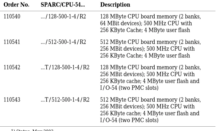
216116 AA June 2002 Modified “Safety Notes” page xxi and “Sicherheitshinweise” page xxv; modified Figure 2 “Block Diagram of the CPU Board” page 1-5; replaced EN 50081/2 with EN 55022/4 in Table 1 “Standard Compliance” page 1-8; modified and updated section “Ordering Information” page 1-9; removed table “Qualified Memory Modules” and accompanying safety note in section “Mem-ory Modules” page 2-8; modified section “Setting the SCSI Termination” page 2-10; corrected description of switch SW5-4 in Figure 5 “SCSI Termination Concept of SPARC/CPU-54 and IOBP-54” page 2-11; modified description of switches 4-3, 4-4, 5-4, 7-1 and 7-2 in Table 9 “Switch Settings” page 2-13; added Figure 7 “Location of Switches on Board’s Bottom Side” page 2-13; modified sections “Boot Devices OTP PROM and Flash EPROM” page 2-18 and “User Application” page 2-18; added information on problem with VMEbus read errors and Solaris 8 version 4/01 to “Installing Solaris” page 2-19 and the “Troubleshooting” chap-ter; moved section “Battery Exchange” to Appendix B; changed Table 15 “Flash Seg-mentation and Write Protection” page 2-23; added description of Ethernet LEDs in Table 16 “Description of Front Panel LEDs” page 3-4; modified section “Serial I/O” page 3-7; deleted section “PCI Control Regis-ter”; modified section “OBDIAG” page 4-10; added chapter “Maps and Registers” page 5-1 from Reference Guide with following mod-ifications: corrected description of signal ID[3..0] in “System Configuration Identifica-tion Register” page 5-14; modified descrip-tion of the Serial Protocol Status register page 5-16; changed description of bits 0-4 in Table 42 “Switch 4 and 5 Status Register” page 5-17; modified description of the
RS-Order No.
SPARC/CPU-54 xix
220991 AA May 2003 Corrected pinout of RS-422 interface
Added information on termination when using RS-422 interfaces
Order No.
Other Sources of Information
For further information refer to the following documents:
Company www. Document
Force Computers forcecomputers.com SPARC/CPU-54 OpenBoot Enhancements Programmer’s Guide (P/N 216134)1)
SPARC/IO-54 Installation Guide (P/N 214901)
SPARC/IOBP-54 Installation Guide (P/N 213170)
SPARC/MEM-54 Installation Guide (P/N 214000)
IEEE Standards Department
ieee.com IEEE P1386 Standard Mechanics for a
Com-mon Mezzanine Card Family: CMC
National Semicon-ductor
national.com PC87307/PC97307 Plug and Play
Compati-ble Super I/O, Preliminary Specification, March 1998
PCI Special Inter-est Group
pcisig.com PCI Local Bus Specification Rev2.1
PICMG
PCI Special Inter-est Group
picmg.org pcisig.com
PCI Local Bus Specification Rev2.2
SUN Microsys-tems
sun.com UltraSPARC-IIE, Draft Datasheet, Aug 25
1999
PCIO (Cheerio, STP2003) Preliminary Datasheet, March 1997
Cheerio Specification, May 1996
Tundra tundra.com Universe II User’s Guide 1997
Universe II Manual Addendum, Rev2, Jun 21, 1999
SPARC/CPU-54 xxi
Safety Notes
This section provides safety precautions to follow when installing, operat-ing, and maintaining the SPARC/CPU-54.
We intend to provide all necessary information to install and handle the SPARC/CPU-54 in this Reference Guide. However, as the product is com-plex and its usage manifold, we do not guarantee that the given informa-tion is complete. If you need addiinforma-tional informainforma-tion, ask your Force Computers representative.
The SPARC/CPU-54 has been designed to meet the standard industrial safety requirements. It must not be used except in its specific area of office telecommunication industry and industrial control.
Only personnel trained by Force Computers or persons qualified in elec-tronics or electrical engineering are authorized to install, maintain, and operate the SPARC/CPU-54. The information given in this manual is meant to complete the knowledge of a specialist and must not be taken as replacement for qualified personnel.
EMC
The board has been tested in a standard Force Computers system and found to comply with the limits for a Class A digital device in this sys-tem, pursuant to part 15 of the FCC Rules, EN 55022 Class A respectively. These limits are designed to provide reasonable protection against harm-ful interference when the system is operated in a commercial, business or industrial environment.
Note: The board is not compliant to EN 55022 if you connect a SCSI de-vice to the SCSI connector on the front panel.
The board generates and uses radio frequency energy and, if not installed properly and used in accordance with this Reference Guide, may cause harmful interference to radio communications. Operating the system in a residential area is likely to cause harmful interference, in which case the user will be required to correct the interference at his own expense.
Installation
Electrostatic discharge and incorrect board installation and removal can damage circuits or shorten their life. Therefore:
• Before installing or removing the board, read the “Action Plan” sec-tion page 2-3.
• Before touching boards or electronic components, make sure that you are working in an ESD-safe environment.
• When plugging the board in or removing it, do not press on the front panel but use the handles.
• Before installing or removing an additional device or module, read the respective documentation.
• Make sure that the board is connected to the VME backplane via all assembled connectors and that power is available on all power pins.
Power Up
If an unformatted floppy disk resides in a floppy drive connected to the SPARC/CPU-54 during power up, the SPARC/CPU-54 does not boot and the OpenBoot prompt does not appear. Therefore, never boot the
SPARC/CPU-54 with an unformatted floppy disk residing in a floppy drive connected to the SPARC/CPU-54.
Operation
While operating the board ensure that the environmental and power requirements are met.
Do not operate the SPARC/CPU-54 outside the specified environmental limits. High humidity and condensation may cause short circuits. Make sure the product is completely dry and there is no moisture on any sur-face before applying power. Do not operate the product below 0°C.
SPARC/CPU-54 xxiii
Replacement/Expansion
Only replace or expand components or system parts with those recom-mended by Force Computers. Otherwise, you are fully responsible for the impact on EMC and the possibly changed functionality of the prod-uct.
Check the total power consumption of all components installed (see the technical specification of the respective components). Ensure that any individual output current of any source stays within its acceptable limits (see the technical specification of the respective source).
System Controller
If more than one system controller is active in the VMEbus system, the board or other VMEbus participants can be damaged. Therefore, always ensure that only one CPU board is configured as system controller in the VMEbus system.
RJ-45 Connector
An RJ-45 connector is used for both telephone and twisted pair Ethernet (TPE) connectors. Mismatching the two connectors may destroy your telephone as well as your SPARC/CPU-54. Therefore:
• TPE connectors have to be clearly marked as network connectors. • The TPE bushing of the system has to be connected only to safety
extra low voltages (SELV) circuits.
Battery
If a lithium battery on the board has to be exchanged, observe the follow-ing safety notes:
• Exchanging the battery always results in data loss of the devices which use the battery as power backup. Therefore, backup affected data before exchanging the battery.
• Incorrect exchange of lithium batteries can result in a hazardous explosion.
• Exchange the battery before seven years of actual battery use have elapsed.
• Always use the same type of lithium battery as is already installed. • Use appropriate tools to remove the battery.
• When installing the new battery, ensure that the dot marked on top of the battery covers the dot marked on the chip.
Environment
SPARC/CPU-54 xxv
Sicherheitshinweise
Dieser Abschnitt enthält Sicherheitshinweise, die bei Einbau, Betrieb und Wartung des SPARC/CPU-54 zu beachten sind.
Wir sind darauf bedacht, alle notwendigen Informationen zum Einbau und zum Umgang mit dem SPARC/CPU-54 in diesem Handbuch bereit zu stellen. Da es sich jedoch bei dem SPARC/CPU-54 um ein komplexes Produkt mit vielfältigen Einsatzmöglichkeiten handelt, können wir die Vollständigkeit der im Handbuch enthaltenen Informationen nicht
garantieren. Falls Ihnen Informationen fehlen sollten, wenden Sie sich bitte an Ihren Vertreter von Force Computers.
Das SPARC/CPU-54 erfüllt die für die Industrie geforderten
Sicherheitsvorschriften und darf ausschließlich für Anwendungen in der Telekommunikationsindustrie und im Zusammenhang mit
Industriesteuerungen verwendet werden.
Einbau, Wartung und Betrieb dürfen nur von durch Force Computers ausgebildetem oder im Bereich Elektronik oder Elektrotechnik
qualifiziertem Personal durchgeführt werden. Die in diesem Handbuch enthaltenen Informationen dienen ausschließlich dazu, das Wissen von Fachpersonal zu ergänzen, können dieses jedoch nicht ersetzen.
EMV
Das Board wurde in einem Force Computers Standardsystem getestet. Es erfüllt die für digitale Geräte der Klasse A gültigen Grenzwerte in einem solchen System gemäß den FCC-Richtlinien Abschnitt 15 bzw. EN 55022 Klasse A. Diese Grenzwerte sollen einen angemessenen Schutz vor Störstrahlung beim Betrieb des Boards in Geschäfts-, Gewerbe- sowie Industriebereichen gewährleisten.
Anmerkung: Das Board erfüllt den Standard EN 55022 nicht, wenn Sie ein SCSI-Gerät am SCSI-Stecker der Frontblende anschließen.
Wenn Sie das Board ohne ein PMC Modul verwenden, schirmen Sie freie Steckplätze mit einer Blende ab, um einen ausreichenden EMV Schutz zu gewährleisten. Wenn Sie Boards in Systeme einbauen, schirmen Sie freie Steckplätze mit einer Blende ab.
Installation
Elektrostatische Entladung und unsachgemäßer Ein- und Ausbau des Boards kann Schaltkreise beschädigen oder ihre Lebensdauer verkürzen. Beachten Sie deshalb die folgenden Punkte:
• Bevor Sie Boards oder elektronische Komponenten berühren, vergewissern Sie sich, dass Sie in einem ESD-geschützten Bereich arbeiten.
• Lesen Sie vor Ein- oder Ausbau des Boards den Abschnitt “Action Plan” auf Seite 2-3.
• Drücken Sie bei Ein- oder Ausbau des Boards nicht auf die Frontblende, sondern benutzen Sie die Griffe.
• Lesen Sie vor dem Ein- oder Ausbau von zusätzlichen Geräten oder Modulen das dazugehörige Benutzerhandbuch.
• Vergewissern Sie sich, dass das Board über alle Stecker an die VME Backplane angeschlossen ist und alle Spannungskontakte mit Strom versorgt werden.
Booten
SPARC/CPU-54 xxvii
Betrieb
Achten Sie darauf, dass die Umgebungs- und die
Leistungsanforderungen während des Betriebs eingehalten werden.
Betreiben Sie das SPARC/CPU-54 nur innerhalb der angegebenen Gren-zwerte für die relative Luftfeuchtigkeit und Temperatur, da durch hohe Luftfeuchtigkeit und Kondensation Kurzschlüsse entstehen können. Stellen Sie vor dem Einschalten des Stroms sicher, dass sich auf dem SPARC/CPU-54 kein Kondensat befindet, und betreiben Sie das SPARC/CPU-54 nicht unter 0°C.
Wenn Sie das Board in Gebieten mit elektromagnetischer Strahlung betreiben, stellen Sie sicher, dass das Board mit dem VME System verschraubt ist und das System durch ein Gehäuse abgeschirmt wird.
Stellen Sie sicher, dass Anschlüsse und Kabel des Boards während des Betriebs nicht berührt werden können.
Prüfen und ändern Sie die Schalterstellungen bevor Sie das Board installieren. Ändern Sie die Stellungen während des Betriebs, kann das Board beschädigt werden.
Austausch/Erweiterung
Verwenden Sie bei Austausch oder Erweiterung ausschließlich von Force Computers empfohlene Komponenten und Systemteile. Andernfalls sind Sie für mögliche Auswirkungen auf EMV und geänderte
Funktionalität des Produktes voll verantwortlich.
Überprüfen Sie die gesamte aufgenomme Leistung aller eingebauten Komponenten (siehe die technischen Daten der entsprechenden Komponente). Stellen Sie sicher, dass die Ausgangsströme jedes Verbrauchers innerhalb der zulässigen Grenzwerte liegen (siehe die technischen Daten des entsprechenden Verbrauchers).
System Controller
RJ-45 Stecker
Das CPU Board ist mit RJ-45 Steckern ausgestattet. Dieser Stecker wird sowohl für Telefonanschlüsse als auch für Netzwerkkabel (Twisted Pair Ethernet - TPE) verwendet. Die Verwechslung dieser Anschlüsse kann sowohl das Telefon als auch das Board zerstören. Beachten Sie deshalb die folgenden Punkte:
• Vergewissern Sie sich, dass Anschlüsse deutlich als Netzwerkanschlüsse gekennzeichnet sind.
• Schließen Sie TPE-Stecker/Netzwerkstecker Ihres Systems nur an Sicherheitskleinspannungskreise (SELV) an.
• Vergewissern Sie sich, dass die an einem TPE-Anschluss
angeschlossene Leitung eine Gesamtlänge von 100 Metern nicht überschreitet.
Falls Sie Fragen haben, wenden Sie sich an Ihren Systemadministrator.
Batterie
Achten Sie beim Austausch der Batterie auf folgende Hinweise: • Fehlerhafter Austausch von Lithium-Batterien kann zu
lebensgefährlichen Explosionen führen.
• Der Austausch der Batterie bringt immer einen Datenverlust bei den batteriegepufferten Komponenten mit sich. Sichern Sie deshalb vor dem Batteriewechsel die betroffenen Daten.
• Tauschen Sie die Batterie aus, bevor sieben Jahre reiner Betriebsdauer verstrichen sind.
• Es darf nur der Batterietyp verwendet werden, der auch bereits eingesetzt ist.
• Verwenden Sie zum Batteriewechsel geeignetes Werkzeug.
• Installieren Sie die Batterie so, dass der Punkt auf der Batterie den Punkt auf dem Chip bedeckt.
1
Introduction Features
SPARC/CPU-54 1 - 3
Features
The SPARC/CPU-54 is the successor of the SPARC/CPU-50. It is a sin-gle-board computer with a processor frequency of 500 MHz and is designed in the 6U VMEbus form factor. It includes a PCI bus sub-system with 32-bit/33 MHz. On-board are:
• Hardware monitor for observing board temperature • OpenBoot diagnostics
• Universe II PCI-to-VMEbus
• PCIO chip with interfaces to the Ebus • Ethernet “Cheerio” controller
• Program-readable registers for board information block (BIB) • System configuration registers
[image:31.595.201.538.354.668.2]The figure shows the major function blocks of the SPARC/CPU-54.
Features Introduction
CPU
The UltraSPARC-IIe CPU with 500 MHz has sensors for observing the CPU on-die temperature and provides the following features:
• Four-way superscalar processor
• SPARC V9 Architecture with the VIS instruction set • 64-bit data path and 44-bit address pointers
• 16 KByte instruction cache
• 16 KByte non-blocking primary data cache • 256 KByte L2-Cache memory
Memory
Memory features include:
• 128 to 512 MByte on-board SDRAM
• 128 to 1536 MByte SDRAM memory module • 1 MByte boot PROM
• Internal memory controller support of up to 2 GB SDRAM • Supports up to 4 MByte user flash
OpenBoot
Introduction Block Diagram
SPARC/CPU-54 1 - 5
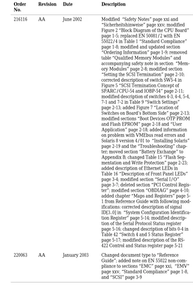
Block Diagram
[image:33.595.200.542.187.654.2]The block diagram shows how the devices of the SPARC/CPU-54 work together and which data paths they use.
CPU Board Variants Introduction
CPU Board Variants
The SPARC/CPU-54 is available as CPU board and also in combination with the I/O-54. If combined with the I/O-54, the SPARC/CPU-54 is called SPARC/CPU-54T and allows the installation of PMC modules.
SPARC/CPU-54
The SPARC/CPU-54 consists of a single-slot CPU board.
Introduction CPU Board Variants
SPARC/CPU-54 1 - 7
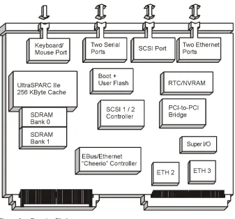
SPARC/CPU-54T
[image:35.595.201.543.185.400.2]The SPARC/CPU-54T consists of a slot CPU board and a single-slot I/O-54, which allows to mount two PMC modules. For further information on the I/O board, refer to the IO-54 Installation Guide.
Standard Compliance Introduction
Standard Compliance
The CPU board was designed to comply with the standards listed below.
[image:36.595.187.534.258.515.2]Note: The board is not compliant to EN 55022 if you connect a SCSI device to the SCSI connector on the front panel.
Table 1: Standard Compliance
Standard Description
IEC 68-2-1/2/3/13/14 Climatic environmental requirements.The SPARC/CPU-54 can only be used in an restricted temperature range (see Table 6 “Environmental Requirements” on page 2-4) for details.
IEC 68-2-6/27/32 Mechanical environmental requirements
EN 609 50/UL 1950 (predefined Force sys-tem);
UL 94V-0/1
Legal safety requirements
EN 55022, EN 55024,
FCC Part 15 Class A
EMC requirements on system level
ANSI/IPC_A-610 Rev. C ANSI/IPC-7711
ANSI/IPC-7721 ANSI-J-001...003
Manufacturing requirements
Introduction Ordering Information
SPARC/CPU-54 1 - 9
Ordering Information
When ordering board variants, upgrades, and accessories, use the order numbers given below.
Product Nomenclature
In the following table you find the key for the product name extensions.
Table 2: Product Nomenclature
SPARC/CPU-54(T)/mmm-sss-c-uu
mmm SDRAM capacity in MByte
sss CPU speed in MHz
c L2-cache
Ordering Information Introduction
Order Numbers
The table below is an excerpt from the board’s ordering information. Ask your local Force Computers representative for the current SPARC/CPU-54 ordering information.
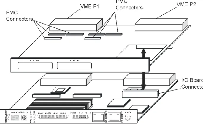
Table 3: Excerpt from the SPARC/CPU-54 Ordering Information for CPU Boards1)
1) Status: May 2003
Order No. SPARC/CPU-54... Description
110540 .../128-500-1-4/R2 128 MByte CPU board memory (2 banks, 64 MBit devices); 500 MHz CPU with 256 KByte Cache; 4 MByte user flash
110541 .../512-500-1-4/R2 512 MByte CPU board memory (2 banks, 256 MBit devices); 500 MHz CPU with 256 KByte Cache; 4 MByte user flash
110542 ...T/128-500-1-4/R2 128 MByte CPU board memory (2 banks, 256 MBit devices); 500 MHz CPU with 256 KByte cache; 4 MByte user flash and I/O-54 (two PMC slots)
[image:38.595.186.537.197.408.2]110543 ...T/512-500-1-4/R2 512 MByte CPU board memory (2 banks, 256 MBit devices); 500 MHz CPU with 256 KByte cache; 4 MByte user flash and I/O-54 (two PMC slots)
Table 4: Excerpt from the SPARC/CPU-54 Ordering Information for Memory Modules 1)
1) Status: May 2003
Order No. SPARC/... Description
107463 .../MEM-54/128 128 MByte memory (2 banks, 64 MBit devices)
107464 .../MEM-54/512 512 MByte memory (2 banks, 256 MBit
devices)
107465 .../MEM-54/1024 1024 MByte memory (4 banks, 256 MBit
devices)
107466 .../MEM-54/1536 1536 MByte memory (6 banks, 256 MBit
Introduction Ordering Information
SPARC/CPU-54 1 - 11
Table 5: Excerpt from the SPARC/CPU-54 Ordering Information for Accessories 1)
1) Status: May 2003
Order No. SPARC/... Description
108771 IOBP-54/3 3-row I/O panel for the CPU-54 and I/O-54
with 3-row P2 connector pinout
108772 IOBP-54/5 5-row I/O panel for the CPU-54 and I/O-54
with 5-row P2 connector pinout
108773 .../CPU-54/AccKit/3 IOBP-54/3 with cables
108774 .../CPU-54/AccKit/5 IOBP-54/5 with cables
105608 .../Sol/Drv/Rel.2.x Solaris driver package
107470 Tornado 2.0 BSP for
CPU-54
2
Installation Action Plan
SPARC/CPU-54 2 - 3
Action Plan
Requirements Installation
Requirements
In order to meet the environmental requirements, the CPU board has to be tested in the system in which it is to be installed.
Before you power up the board, calculate the power needed according to your combination of board upgrades and accessories.
Environmental Requirements
The environmental conditions must be tested and proven in the used system configuration. The conditions refer to the surrounding of the board within the user environment.
Note: Operating temperatures refer to the temperature of the air cir-culating around the board and not to the actual component tempera-ture.
Caution
• To ensure that the operating conditions are met, forced air cooling is required within the chassis environment.• Do not operate the SPARC/CPU-54 outside the specified environ-mental limits. High humidity and condensation may cause short circuits. Make sure the product is completely dry and there is no moisture on any surface before applying power. Do not operate the product below 0°C.
Table 6: Environmental Requirements
Feature Operating Non-Operating
Temperature 0°C to +55°C -40°C to +85°C
Forced airflow 300 LFM (linear feet per minute)
Installation Requirements
SPARC/CPU-54 2 - 5
Power Consumption
The SPARC/CPU-54 power consumption depends on the installed hardware accessories. In the following table you will find typical exam-ples of power consumption without any accessories installed. If you want to install accessories on the SPARC/CPU-54, the load of the respective accessory has to be added to the used SPARC/CPU-54 vari-ant. For information on the accessories’ power consumption, refer to the documentation delivered together with the respective accessory or con-sult your local Force Computers representative for further details.
The installation of the SPARC/CPU-54 requires:
• +5V power supply
• Minimum airflow meeting the thermal requirements (see Table 6 “Environmental Requirements” on page 2-4)
• One slot of a VMEbus backplane with P1 and P2 connectors
The installation of the SPARC/CPU-54T requires:
• +5V and +12V power supply
• Minimum airflow meeting the thermal requirements (see Table 6 “Environmental Requirements” on page 2-4)
• Two slots of a VMEbus backplane with P1 and P2 connectors
Vibration 10 to 15 Hz 15 to 150 Hz
2 mm amplitude 2 g
5 mm amplitude 5 g
Shock 5g/11 ms halfsine 15g/11 ms halfsine
Free fall 100 mm / 3 axes 1200 mm / all edges and
corners (packed state)
Table 6: Environmental Requirements (cont.)
Requirements Installation
The power supply has to meet the requirements given in the tables be-low.
Caution
In order to protect its components, the SPARC/CPU-54 only powers up if the 5V supply voltage is stable and within its limits. The SPARC/CPU-54T only powers up if the 5V and 12V supply voltages are stable and within their limits. This is in compliance with the VMEbus specification. However, there are systems which are not fully VMEbus-compliant. The power supplies of these systems do not turn on the 12V supply if the 5V supply has not been loaded before. Use a VMEbus board in the system which loads the 5V to prevent such systems from running into a power-up deadlock.Table 7: Maximum Power Consumption
CPU Board +5V +12V Major Components
SPARC/CPU-54/ 128-400-1-4
4.5A n.a. CPU-54 400 MHz, 128 MByte
SDRAM
SPARC/CPU-54/ 512-500-1-4
5.0A n.a. CPU-54 500 MHz, 512 MByte
SDRAM
SPARC/CPU-54T/ 128-400-1-4
6.0A 500mA CPU-54 400 MHz, 128 MByte
SDRAM, including I/O-54
SPARC/CPU-54T/ 512-500-1-4
7.5A 500mA CPU-54 500 MHz, 512 MByte
SDRAM, including I/O-54
Table 8: Maximum Power Consumption with SPARC/MEM-54 Installed
MEM Board +5V +12V Major Components
SPARC/MEM-54/128 1A n.a. 128 MByte, SDRAM
Installation Requirements
SPARC/CPU-54 2 - 7
Software Requirements
If you wish to use one of the SPARC/CPU-54 devices listed below you need to install the Force Computers Solaris Driver Package Version 2.11 or higher:
• Intel 82559 Ethernet device
• Universe II PCI-to-VMEbus bridge • On-board Flash memory
• Temperature sensors, LEDs, seven-segment display, watchdog and floppy ejection
Hardware and Software Upgrades and Accessories Installation
Hardware and Software Upgrades and Accessories
The following upgrades and accessories are available for the SPARC/CPU-54:
• SPARC/MEM-54 memory module • IO-54
• IOBP-54
• Solaris Driver Package
Memory Modules
The main memory capacity is adjustable via installation of the Force Computers memory module SPARC/MEM-54. The following memory module variants are available:
• SPARC/MEM-54/128 with 128 MByte additional memory • SPARC/MEM-54/512 with 512 MByte additional memory • SPARC/MEM-54/1024 with 1024 MByte additional memory • SPARC/MEM-54/1536 with 1536 MByte additional memory
For installation information, see the SPARC/MEM-54 Installation Guide.
IO-54
The SPARC/CPU-54T includes an I/O board, the SPARC/IO-54, which can be plugged onto the CPU board. The SPARC/IO-54 serves as a car-rier board and provides connectors for two PMC modules
Note: The I/O board has to be mounted on the CPU board before the CPU board is installed into the system.
Installation Hardware and Software Upgrades and Accessories
SPARC/CPU-54 2 - 9
SPARC/IOBP-54
As a separate price list item an I/O back panel is available for the CPU board, the SPARC/IOBP-54. It is part of the SPARC/CPU-54/AccKit3/5 Accessory Kit. The SPARC/IOBP-54 provides access to the CPU board’s user I/O interfaces via industry standard connectors.
Note: The IOBP has to be connected to the CPU board after it has been installed in the system.
For further information, refer to the IOBP-54 Installation Guide.
Caution
• The SPARC/IOBP-54 is especially designed for the SPARC/CPU-54. Do not use any other I/O back panels on the SPARC/CPU-SPARC/CPU-54. Otherwise, the board may be damaged.• The IOBP-54 provides automatic SCSI termination. Therefore, SW5-2 on the CPU board must be configured appropriately to dis-able the corresponding backplane SCSI termination.
Solaris Driver Package
Force Computers provides a Solaris driver package which supports the following devices and features of the SPARC/CPU-54:
• Intel 82559 Ethernet device
• Universe II PCI-to-VMEbus bridge • On-board flash memory
• Temperature sensors, LEDs, seven-segment display, watchdog and floppy ejection
If you wish to use one of these devices you need to install the Force Computers Solaris Driver Package Version 2.11 or higher.
Setting the SCSI Termination Installation
Setting the SCSI Termination
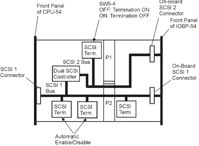
The SPARC/CPU-54 provides two Ultra Wide SCSI buses. SCSI 1 is accessible via the front panel and the backplane via the IOBP-54. SCSI 2 is available via the backplane via the IOBP-54. The SPARC/CPU-54 enables and disables the SCSI termination automatically according to the board’s position in the SCSI bus, if switch SW5 is set to the respec-tive default settings.
SCSI 1 Termination
The SCSI 1 bus is available via the front panel connector and via the VMEbus P2 connector and the IOBP-54. By default, switch SW5-2 is set to OFF and switch SW5-3 is set to ON to enable automatic termination of the SCSI bus 1. To guarantee proper termination, leave switches in the mentioned position.
Caution
Only connect the SCSI cable at its end connectors and never at its middle connectors. Otherwise, data may be lost.SCSI 2 Termination
Caution
If you use a flat ribbon T-cable at the SCSI 2 bus, the termination of SCSI 2 has to be set manually to prevent data transmission errors. Before installing the board, check Figure 5 “SCSI Termination Con-cept of SPARC/CPU-54 and IOBP-54” on page 2-11 whether this applies to your planned configuration.Installation Setting the SCSI Termination
SPARC/CPU-54 2 - 11
[image:51.595.201.538.154.401.2]The figure below shows the SCSI bus termination concept on the SPARC/CPU-54 and the IOBP-54.
Switch Settings Installation
Switch Settings
Caution
The switch settings have to be checked and changed before the board installation. Do not set/reset the switches during operation. Other-wise, the board is damaged. [image:52.595.184.463.267.472.2]The SPARC/CPU-54 provides five configuration switches: SW4, SW5, SW6, SW7, and SW800. Switches SW4, SW6 and SW7 are located on the top side (see figure below).
Installation Switch Settings
SPARC/CPU-54 2 - 13
[image:53.595.200.493.145.373.2]The switches SW5 and SW800 are located on the bottom side of the board.
Figure 7: Location of Switches on Board’s Bottom Side
Table 9: Switch Settings
Switch No. Description
SW4 1 Abort key control
OFF (default): ABORT key enabled ON: ABORT key disabled
2 Reset key on front panel control OFF (default): RESET key enabled ON: RESET key disabled
3 Flash EPROM write protection
OFF (default): Flash EPROM write protected ON: Flash EPROM write enabled
Switch Settings Installation
SW5 1 Termination for SCSI 1 on front panel
OFF (default): Front panel termination automatic ON: Front panel termination disabled
2 Termination for SCSI 1 on P2
OFF (default): Manual termination enabled ON: Manual termination disabled
3 Automatic termination for SCSI 1 on P2 OFF: Automatic termination disabled ON (default): Automatic termination enabled
4 Manual SCSI termination for SCSI 2 on P2 OFF (default): Termination enabled ON: Termination disabled
SW6 1 Reserved, must be OFF
2 Boot device selection
OFF (default): Boot from OTP PROM ON: Boot from flash EPROM
3 VMEbus SYSRESET on power-up
OFF (default): Enabled ON: Disabled
4 Watchdog enable switch
OFF (default): Disabled ON: Enabled
SW7 1 Serial interface A control selection
OFF (default): RS-232 ON: RS-422 (factory option)
2 Serial interface B control selection OFF (default): RS-232
ON: RS-422 (factory option)
3 Reserved, must be OFF
4 Reserved, must be OFF Table 9: Switch Settings (cont.)
Installation Switch Settings
SPARC/CPU-54 2 - 15
SW800 1 Automatic VMEbus slot-1 detection
OFF (default): Automatic detection of VMEbus slot-1 function
ON: Automatic detection of VMEbus slot-1 function disabled. Set SW800-2 appropriately.
2 Manual VMEbus slot-1 selection - only relevant if SW800-1 is ON
OFF (default): VMEbus slot-1 function enabled ON: VMEbus slot-1 function disabled
3 External VMEbus SYSRESET
OFF (default): VMEbus SYSRESET generates on-board RESET
ON: VMEbus SYSRESET does not generate on-board RESET
4 VMEbus SYSRESET generation
OFF (default): SYSRESET is driven to VMEbus ON: SYSRESET is not driven to VMEbus
Table 9: Switch Settings (cont.)
Board Installation Installation
Board Installation
The SPARC/CPU-54 can be installed in a system with or without the IO-54.
Caution
The SPARC/CPU-54 has to be installed in a non-powered system. If you install the SPARC/CPU-54 in or remove it from a powered sys-tem, the system board and other cards installed may be damaged.Backplane Configuration
If the CPU board is plugged into slot 1 and configured accordingly with switches SW800-1 and SW800-2 (see Table 9 “Switch Settings” on page 2-13), the board acts as IACK daisy-chain driver. Plugged in any other slot, the board closes the IACKIN-IACKOUT path.
If one board is missing in this daisy chain, an active backplane will be able to automatically transfer the signals to the next board in the chain. If the board is not plugged into an active backplane, jumpers on the backplane will transmit the signals. The jumpers have to be set manual-ly. In order to do so, proceed as follows:
1. Remove jumpers connecting BG3IN* and BG3OUT* signals
from empty slot on backplane where SPARC/CPU-54 is to be
plugged into backplane
2. Assemble jumpers for BG3IN* and BG3OUT* signals on lower
and higher slots on backplane where no board is plugged to
ensure that daisy chain is not interrupted
Installation Board Installation
SPARC/CPU-54 2 - 17
Caution
If more than one system controller is active in the VMEbus system, the board or other VMEbus participants can be damaged. Therefore, always ensure that only one CPU board is configured to be system controller in the VMEbus system.Installing the CPU Board
1. Check system documentation for all important steps to be
taken before switching off power
2. Take those steps
3. Switch off power
Caution
Before installing the board, check switch settings for consistency (see Table 9 “Switch Settings” on page 2-13).4. Plug board into system slot on left-hand side
Note: Make sure all other boards which are plugged into the system are to the right of the system board.
5. Fasten board with screws
6. Plug interface cables into front panel connectors, if applicable
7. Switch on power
Removing the CPU Board
1. Check system documentation for all important steps to be
taken before switching off power
2. Take those steps
3. Switch off power
4. Remove interface cables, if applicable
5. Unfasten screws
Board Installation Installation
Powering Up
We recommend to use a terminal when powering up the
SPARC/CPU-54. The advantage of using a terminal is that you do not need any frame buffer, monitor, or keyboard for initial powering up.
Note:
• Before powering up, check the “Requirements” section on page 2-4 for installation prerequisites and requirements.
• If an unformatted floppy disk resides in a floppy drive connected to the SPARC/CPU-54 during power up, the SPARC/CPU-54 does not boot and the OpenBoot prompt does not appear.
• Check the consistency of the switch settings (Table 9 “Switch Set-tings” on page 2-13).
In order to power up the CPU board, proceed as follows:
1. Connect terminal to front panel serial I/O interface A
For information on the serial interface connector pinout, see
the “On-Board Connectors of the SPARC/CPU-54” section on
page 3-10.
2. Switch on system
The monitor will display information about the OpenBoot
booting process.
3. Enter OpenBoot commands, if applicable
Boot Devices OTP PROM and Flash EPROM
By default, the SPARC/CPU-54 boots from the 1 MByte OTP PROM (PLCC socket device) which is not writeable and contains the OpenBoot firmware. Alternatively, a 4 MByte flash EPROM device can be enabled with SW6-2. This flash EPROM device is rewriteable if enabled by SW4-3.
Installation Board Installation
SPARC/CPU-54 2 - 19
Installing Solaris
The SPARC/CPU-54 is designed to run with Solaris Version 8 10/00 or higher with the 64-bit kernel. Pay attention to the guidelines in this sec-tion before and during Solaris installasec-tion.
Note:
• Solaris versions prior to version 8 10/00 are not supported. SPARC/CPU-54 runs with 64-bit kernel only.
• If a VME bus read error (e.g. bus time-out) occurs and Solaris 8 version 4/01 is used, Solaris sometimes shuts down the system unexpectedly. To avoid this problem, install Solaris 8 kernel patch 108528-12 or higher. For information on how to install it, refer to the README file contained in the zip file.
The following devices of the SPARC/CPU-54 are not supported by the Solaris operating system:
• Intel 82559 Ethernet device
• Universe II PCI-to-VMEbus bridge • On-board flash memory
• Temperature sensors, LEDs, seven-segment display, watchdog, and floppy ejection
Board Installation Installation
Solaris 8
When setting up Solaris interactively, these packages can be installed by selecting/deselecting the proper software group in the software dialog window. If applicable, customize the software group as shown in the following table.
Note: During installation, make sure that the 64-bit support is en-abled.
If a PS/2 keyboard and mouse is used, the package shown in the table below is available.
Note: During the boot process, the following warning may appear: WARNING: i2c_client_register_failed. If this should be the case, the warning can be ignored as it has no impact on the boot pro-cess.
Table 10: Customizing Solaris 8
Software Group Customizing
Entire distribution plus OEM support No customizing required
Entire distribution No customizing required
If a PS/2 keyboard/mouse is used, proceed as follows:
Under “drivers for SME support (64 Bit)”, select “PS/2 keyboard and mouse device drivers (Root, 64 Bit).
Developer system support
End user system support
Core system support
Table 11: Required Solaris Package for Solaris 8
Package Description
Installation Board Installation
SPARC/CPU-54 2 - 21
Solaris Driver Package
The following table shows which driver has to be installed for a particu-lar device.
For further information on the Solaris Driver Packages Release 2.11, refer to the following sections and to the documentation delivered together with the package. For information on how to install the respec-tive driver, see the Solaris Driver Packages Release 2.11 Installation Guide.
FRCiprb The assignment of the driver’s instance number to an Intel 82559 Ether-net device can be viewed by booting with the OpenBoot command boot -rv. Each device is shown with the driver name and instance num-ber during the Solaris boot up.
The other way to obtain the instance number of the Ethernet devices is to look into the file /etc/path_to_inst. In order to do so, type the com-mand:
grep fciprb /etc/path_to_inst
Typical output:
“/pci@1f,0/pci@3/ethernet@2” 1 “fciprb” “/pci@1f,0/pci@3/ethernet@1” 0 “fciprb”
The first part (in quotation marks) specifies the hardware node name in the device tree. The number specifies the instance number and the third part (also in quotation marks) specifies the driver name.
Table 12: Devices and Their Appropriate Drivers
Device Driver Name
Intel 82559 Ethernet controller FRCiprb
Universe II PCI-to-VMEbus bridge FRCvme
On-board flash memory FRCflash
Temperature sensors, LEDs, seven-seg-ment display, watchdog, floppy ejection
Board Installation Installation
The following table shows how the hardware node names are assigned to a label on the front panel and the IOBP.
The following table shows how the driver instance numbers are typi-cally assigned to Ethernet devices on the SPARC/CPU-54 (without IO-54) and the SPARC/CPU-54T (with IO-54).
FRCvme The FRCvme is a set of drivers which handles the Universe II device. The following functions are supported:
• Master windows • Slave windows • Interrupts • DMA controller • VME arbiter • Mailboxes
Additionally, the FRCvme package provides a common programming interface for application and driver development to the FRCvme pack-age and a detailed description of the software interface and sample pro-grams.
Table 13: Hardware Node Assignment
Label Location Hardware Node
ETHERNET1 CPU front panel /pci@1f,0/network@1,1 (standard
Solaris hme Ethernet device)
ETHERNET2 CPU IOBP /pci@1f,0/pci@3/ethernet@1
ETHERNET3 CPU front panel /pci@1f,0/pci@3/ethernet@2
Table 14: Instance Number Assignment for SPARC/CPU-54
Label Location Driver Instance Number
ETHERNET1 CPU front panel hme0
ETHERNET2 CPU IOBP fciprb0
Installation Board Installation
SPARC/CPU-54 2 - 23
FRCflash The Solaris 2.x flash memory driver provides access to the flash EPROM device. According to the SPARC/CPU-54(T) switch settings, the flash EPROM is accessible as one user flash or is divided into a boot and a user section.
The following table shows the effects the different CPU board switch settings have on the flash segmentation and the flash write protection.
FRCctrl The FRCctrl driver contains the sysconfig device driver which offers the following features:
• Sets all user LEDs.
• Sets the seven-segment display.
• Accesses the temperature sensor devices.
To enable the temperature sensors, set the OpenBoot environment variable env-monitor before booting. To do so, enter at the prompt:
setenv env-monitor enabled
• Handles the floppy disk eject pin.
• Enables and triggers watchdog functions.
To enable the watchdog, set switch SW6-4 to ON.
Table 15: Flash Segmentation and Write Protection
SW4-3 SW6-2 Flash Segmentation and Write-Protec-tion
Boot from
OFF OFF 4 MByte user section, write-protected Boot
PROM
ON OFF 4 MByte user section, not write-protected Boot PROM
OFF ON 1 MByte boot section, write-protected
3 MByte user section, write-protected
Flash PROM
ON ON 1 MByte boot section, not write-protected 3 MByte user section, not write-protected
3
Controls, Indicators, and Connectors Front Panel of the SPARC/CPU-54
SPARC/CPU-54 3 - 3
Front Panel of the SPARC/CPU-54
The following figure shows the connectors, keys and LEDs available on the front panel of the SPARC/CPU-54. For the front panel features of the IO-54, see the IO-54 Installation Guide.
Front Panel of the SPARC/CPU-54 Controls, Indicators, and Connectors
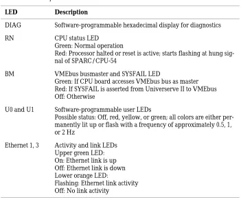
LEDs
The figure below shows the LEDs available on the SPARC/CPU-54.
[image:68.595.184.535.279.576.2]Figure 9: Front Panel LEDs
Table 16: Description of Front Panel LEDs
LED Description
DIAG Software-programmable hexadecimal display for diagnostics
RN CPU status LED
Green: Normal operation
Red: Processor halted or reset is active; starts flashing at hung sig-nal of SPARC/CPU-54
BM VMEbus busmaster and SYSFAIL LED
Green: If CPU board accesses VMEbus bus as master Red: If SYSFAIL is asserted from Universerve II to VMEbus Off: Otherwise
U0 and U1 Software-programmable user LEDs
Possible status: Off, red, yellow, or green; all colors are either per-manently lit up or flash with a frequency of approximately 0.5, 1, or 2 Hz
Ethernet 1, 3 Activity and link LEDs Upper green LED: On: Ethernet link is up Off: Ethernet link is down Lower orange LED:
Controls, Indicators, and Connectors Front Panel of the SPARC/CPU-54
SPARC/CPU-54 3 - 5
Keys
The front panel of the SPARC/CPU-54 provides two mechanical keys and a hexadecimal rotary switch (front panel shows MODE).
Reset
When enabled and toggled, it instantaneously affects the CPU board by generating a push-button Power On Reset (POR) to the UltraSPARC-IIe. Push-button Power On Reset has the same effect as a Power On Reset from the power supply, with the only difference, that the corresponding status bit (B_POR) in the UltraSPARC-IIe Reset_Control Register is set and the DRAM refresh is not influenced.
Abort
When enabled and toggled, it instantaneously affects the CPU board by generating a push-button external initiated reset (XIR). Push-button external initiated reset allows a user-reset (abort) of part of the proces-sor without resetting the whole system. UltraSPARC-IIe sets the B_XIR bit in the Reset_Control Register when a push-button external initiated reset is detected.
Mode
Front Panel of the SPARC/CPU-54 Controls, Indicators, and Connectors
Connectors
By means of the front panel connectors, the peripherals can be con-nected to the SPARC/CPU-54.
Ethernet
Two full duplex Ethernet interfaces are available at the front panel via the 10BaseT/100BaseTx Twisted-Pair-Ethernet (TPE) connectors.
Figure 10: Twisted-Pair Ethernet Connector Pinout
The Ethernet #1 interface is also accessible at the 5-row P2 back panel connector. For the connector pinout see Figure 17 “P2 VMEbus Connec-tor Pinout Continued Rows C+D” on page 3-12.
Controls, Indicators, and Connectors Front Panel of the SPARC/CPU-54
SPARC/CPU-54 3 - 7
Serial I/O
The serial interface on the CPU board’s front panel holds the signals for the two serial interfaces A and B. If you want to use both interfaces you need a splitter cable.
Both serial I/O interfaces of the CPU board are independent full-duplex channels. For each of them, the four signals RXD, TXD, RTS, and CTS are also provided via the respective VMEbus P2 connector.
Both I/O interfaces can be configured as RS-232 and RS-422. The selec-tion is made via the switches SW7-1 and SW7-2.
Note: When configuring the serial interfaces as RS-422 and you want to terminate the signals RxD+/- and CTS+/-, you have to mount termi-nation resistors into the serial cable you use. These resistors are not assembled on the CPU board.
The following figures show the pinout of the 26-pin connector in RS-232 and RS-422 mode (factory option).
Figure 11: Serial A+B Connector Pinout RS-232
Front Panel of the SPARC/CPU-54 Controls, Indicators, and Connectors
Keyboard/Mouse
A SUN-type keyboard/mouse is available at the front panel via an 8-pin mini-DIN connector. The pinout can be seen in the following figure.
Figure 13: Keyboard/Mouse Connector Pinout SUN-Type Function
If using an adapter a PS/2-type interface is also available. The pinout of the PS/2-type interface can be seen in the following figure.
Controls, Indicators, and Connectors Front Panel of the SPARC/CPU-54
SPARC/CPU-54 3 - 9
SCSI
The following connector pinout shows the signals of the ultra-wide SCSI connector.
[image:73.595.205.495.207.516.2]Note: The board is not compliant to EN 55022 if you connect a SCSI device to the SCSI connector on the front panel.
On-Board Connectors of the SPARC/CPU-54 Controls, Indicators, and Connectors
On-Board Connectors of the SPARC/CPU-54
In addition to the front panel connectors, the CPU board provides back-plane connectors and on-board connectors for memory modules and for the IO-54.
Table 17: On-Board Connectors
Connector Description and Location Connector Type
VMEbus backplane connector P1 VG 96-pin connector male
VMEbus backplane connector P2 VG 160-pin connector male
(in case of three-row factory option VG 96-pin connector male)
IO-54 connector P6 100-pin MBus connector male
Memory module connectors P5, P7 100-pin SMD connector
Table 18: P2 Backplane Connector Signals
Interface Backplane Connector
Ultra-wide SCSI #1 P2 row A+C
Ethernet #1 interface P2 row Z
Ethernet #2 interface P2 row Z
Floppy interface P2 row C
Parallel interface P2 row C
Serial interface A P2 row A
Serial interface B P2 row C
Controls, Indicators, and Connectors On-Board Connectors of the SPARC/CPU-54
SPARC/CPU-54 3 - 11
The signal names used in the following pinouts are given in brackets:
• Floppy (FDC)
• Fused 5V power (VP5)
• Keyboard (KBD) and mouse (MSE) • Ethernet 1 (TP1R)
• Ethernet 2 (TP2R) • Parallel (LPT) • SCSI (SCSI)
• Serial interface A (SerA) and serial interface B (SerB)
The standard CPU board is delivered with a five-row P2 VMEbus con-nector. However, a three-row P2 connector variant is also available as factory option.
[image:75.595.198.532.374.666.2]Note: If the three-row P2 VMEbus connector is used, the rows Z and D are not active.
On-Board Connectors of the SPARC/CPU-54 Controls, Indicators, and Connectors
4
OpenBoot Firmware Introduction
SPARC/CPU-54 4 - 3
Introduction
The OpenBoot firmware consists of the Common Operations and Reset Environment (CORE), the POST, the OpenBoot Diagnostics (OBDIAG), and the OpenBoot itself as well as support for the VxWorks RTOS.
The OpenBoot firmware is subject to changes. For the newest version and how to upgrade refer to the SMART service accessible via the Force Com-puters World Wide Web site (www.forcecomCom-puters.com).
Note: The appearance of the on-screen output shown in the examples can differ from the appearance of the output on your monitor according to your device tree (CPU architecture).
For more information on the OpenBoot firmware, see the OpenBoot 4.x Manual Set.
CORE
CORE is responsible for setting up proper environments for booting pur-poses. It first initializes the system to a status where different firmware can be loaded from.
CORE automatically transfers control to its clients (such as OpenBoot, VxWorks, Chorus Booter...) during power up.
Introduction OpenBoot Firmware
[image:80.595.168.483.148.320.2]The following figure gives a system overview of which systems are initial-ized by CORE.
Figure 18: System Overview
Additionally, CORE is designed to reach the following goals:
• Ability to use I/O devices including serial port, flash, floppy, and net early on the cold boot sequence of a firmware client.
• Basic system tests that can replace existing POST in min. mode. • System testing may be done using the POST drop-in in max. mode. • Error recovery from exceptions which currently do not exist in
Open-Boot and from any fatal conditions during flash update
• Developing standard validation test suites that could prevent major bugs in CORE and clients
OpenBoot Firmware Introduction
SPARC/CPU-54 4 - 5
CORE Workflow