Original citation:
Li, Dezhi. (2017) Influence of local surface texture by tool impression on the self piercing riveting process and the static lap shear strength. Journal of Manufacturing Processes, 29 . pp. 298-309.
Permanent WRAP URL:
http://wrap.warwick.ac.uk/91280
Copyright and reuse:
The Warwick Research Archive Portal (WRAP) makes this work by researchers of the University of Warwick available open access under the following conditions. Copyright © and all moral rights to the version of the paper presented here belong to the individual author(s) and/or other copyright owners. To the extent reasonable and practicable the material made available in WRAP has been checked for eligibility before being made available.
Copies of full items can be used for personal research or study, educational, or not-for-profit purposes without prior permission or charge. Provided that the authors, title and full bibliographic details are credited, a hyperlink and/or URL is given for the original metadata page and the content is not changed in any way.
Publisher’s statement:
© 2017, Elsevier. Licensed under the Creative Commons Attribution-NonCommercial-NoDerivatives 4.0 International http://creativecommons.org/licenses/by-nc-nd/4.0/
A note on versions:
The version presented here may differ from the published version or, version of record, if you wish to cite this item you are advised to consult the publisher’s version. Please see the ‘permanent WRAP url’ above for details on accessing the published version and note that access may require a subscription.
Influence of local surface texture by tool impression on the
self-piercing riveting process and the static lap shear strength
Dezhi Li
WMG, University of Warwick, Coventry, CV4 7AL, UK
Tel: +44 (0)2476574614, Fax: +44 (0)2476575366, E-mail:[email protected]
Abstract
To increase fuel efficiency and reduce emission, aluminium alloys have been increasingly used in
automotive body-in-white structures for lightweighting. Due to its advantages over some of the more
traditional joining technologies, self-piercing riveting (SPR) has been widely used for these
lightweight structures. Research has showed that friction is a very important factor that influences
both the riveting process and joint strength for SPR, but these influences have not been fully
understood. In this paper, an innovative method was used to modify the local surface of the top sheet
around the rivet piercing location with different impression tools (the central pin, the small ring, the
medium ring and the large ring) and garnet particles to study the influence of local frictions on rivet
inserting process, joint features and static lap shear strength. The results showed that the local surface
textures on the aluminium sheet did not have significant influence on the rivet inserting process based
on displacement-force curve analysis. The local surface textures could slightly change the joint
features, especially the rivet head height, but overall this influence was not significant. The lap shear
tests showed that ring impressions with garnet particles and central pin impressions on the bottom
surface of the top sheet increased the static lap shear strength of the SPR joints. The results confirmed
that the critical location for local friction influence on the lap shear strength was around the rivet leg
piercing location.
1. Introduction
In order to increase fuel efficiency and reduce CO2 emission, aluminium is increasingly used in
automotive body-in-white structures for lightweighting. Self-piercing riveting (SPR) is one of the
main joining methods for aluminium and mixed material structures due to its advantages in clean
working environment, ability to join dissimilar materials, low energy requirement and high static and
fatigue joint strengths etc. [1].
Friction is an important factor for installation and strength of mechanical joints. For example, the
friction between the bolt, nut and joint members will influence the tighten torque applied to the joint
members of the bolted joints and the friction between the joint members will contribute or decide the
shear strength of the bolted joints [2, 3]. As a mechanical joining process, friction is very important
for both the SPR rivet setting process and joint strength due to the relative movements between
different components, and the frictions existing in a SPR setting process or a SPR joints can be
between sheet materials and between rivet and sheet materials. As we know, friction between two
surfaces is related with the surface conditions. To find out the influence of surface conditions and
friction on SPR setting process and joint strength, some research had been conducted [4-7] . These
research on the influence of surface conditions on SPR joint quality and performance have been
reviewed by Li et al [1].
Han and Chrysanthou [4] and Han et al. [7] studied the influence of coatings on sheet material on
the joint quality and mechanical strength of SPR joints. In their study, AA5754 was used as the top
sheet, and HSLA 350 with different coatings, i.e. uncoated, e-coated and zinc plated, was used as
bottom sheet. Their results showed that the extent of the effects of surface coatings on the joint quality
and mechanical behaviour of SPR joints differed significantly with different types of coatings on the
HSLA steel. Han et al. [5] studied the influence of sheet/sheet interfacial condition on the fatigue
significantly reduced fretting damage, but led to a reduction in the fatigue life due to a different
failure mode. Research from Li et al. [6] showed that fretting during fatigue increased the surface
roughness, which consequently increased the remaining static lap shear strength of the specimens due
to the increased friction force between the tip of the punched hole in the top sheet and the edge of the
partially pierced hole in the bottom sheet.
Friction is also a very important aspect for SPR simulation. In the models for simulation, different
researchers have used different coefficients of friction. A value of 0.1 was used by Xu [8], a value of
0.15 was used by Khezri et al. [9], and a value of 0.2 was used by Abe et al. [10], for all interfaces.
Other researchers used different friction coefficients at different locations. For example, Krishnappa
[11] used the friction coefficients of 0.15 and 0.3 at different locations. Atzeni et al. [12] used a
friction coefficient of 0.2 for the interfaces between the punch and the rivet and between the rivet and
the sheet, a friction coefficient of 0.1 for the interface between the bottom sheet and the die, and a
friction coefficient of 0.15 for the interface between the top and bottom sheets. In the model used by
Carandente et al. [13], the friction coefficient used for the interface between the top and bottom
sheets, the interface between the bottom sheet and the die, and the interface between the top sheet and
the blank holder were 0.09, 0.15, and 0.15, respectively. However, to find out the actual friction
coefficients at different interfaces is quite difficult due to the variation of applied pressure and surface
texture etc.
Apart from conventional SPR, the influence of friction on flat-bottom self-piercing riveting
(different from convenient SPR, a flat plate is used instead of a die with a cavity) was also studied.
Han et al. [14] studied the influence of friction on the joint quality of flat-bottom self-piercing riveted
AZ31 magnesium alloy joints through simulation. The friction at different locations, between the bank
holder and the top sheet, between the rivet and the sheet materials, between the top and the bottom
materials and between the bottom sheet material and the bottom plate, was studied, and the
The friction during a SPR rivet setting process and in a joint load sustaining state is very complex
due to the existing of multiple friction interfaces. Currently, no critical friction locations have been
confirmed through experiments or simulation, and the influence mechanisms of friction on rivet
setting and joint strength need further understanding. In order to find out some of the critical friction
locations for SPR, in this paper, the influence of local surface textures of aluminium AA5754 by tool
impression on rivet inserting process, joint features and static lap shear strength was studied.
2. Experimental procedure
2.1. Materials
The material used in this study is 2.0 mm thick AA5754 with a standard PT2 pretreatment and an
AL070 wax lubricant. The AA5754 has an UTS, a yield strength and an elongation of 241 MPa, 110
MPa and 25%, respectively.
2.2. Local surface modification
In order to see the influence of local surface texture, especially roughness, on the SPR
riveting process and joint strength, the bottom surface of the top sheet before rivet inserting
was modified using various impression tools listed in Fig. 1, at the locations indicated in Fig.
2. The impression tools were custom made so that it can be attached to the nosepiece of our
Henrob SPR gun, as shown in Fig. 3. A pre-set force from the SPR gun used for stack
thickness measurement, 8kN, was used for the impression. A dummy die (top face diameter,
18 mm) without any cavity was used to support the sheet material. For joint quality analysis
and SPR setting process study, 38 mm square coupons were used, and for lap shear
specimens, 111.5 mm x 48 mm coupons were used. For one surface modification, the
when the coupon was turned over, the impression would still be at the same location. Since
the impressions may introduce work hardening in addition to surface texture, it is essential to
separate the influence of work hardening from the influence of surface texture. It is assumed
that the impressions with tools without particles would only introduce work hardening,
because it did not make the surface rougher. For this reason, some of the impressions were
done with the impression tools only to see the influence of potential work hardening. Most of
the impressions were done with the impression tools and small garnet particles for grit
blasting. Among the coupons modified with the impression tools and garnet particles, half of
them, particles were remained on the impression location, and the other half, particles were
removed with fingernails as much as possible although some particle residuals must be still
trapped in. Totally 15 stacks were evaluated, and the base stack is 2 mm AA5754 joined to 2
[image:6.595.85.499.412.612.2]mm AA5754.
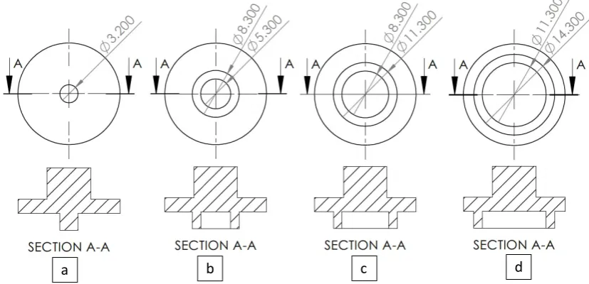
Figure 1Geometries of the impression heads, a), with a central pin, b), with a small ring, c), with a medium ring and d) with a large ring (unit, mm).
Figure 2Locations of local impression and surface modification on the bottom surface of the top sheet before rivet inserting.
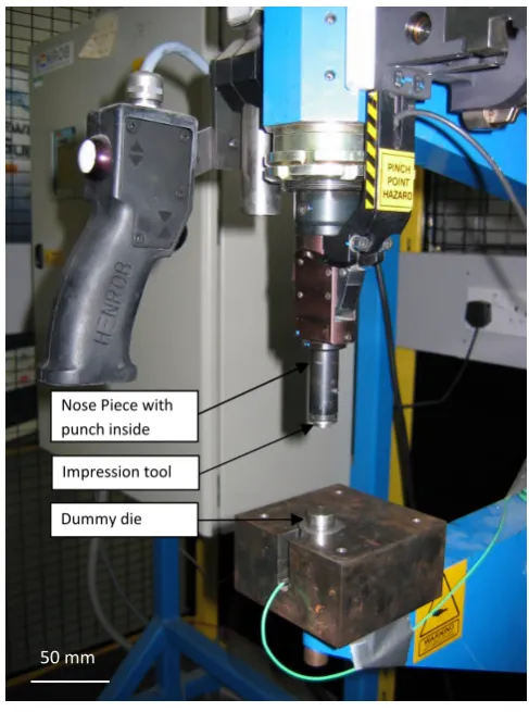
Figure 3SPR gun with one impression tool and the dummy die.
Nose piece
5.35 mm
with central pin, with the small ring, with
the medium ring, and with the large ring.
Die
Impression tool Nose Piece with punch inside
Dummy die
[image:7.595.175.419.328.656.2]2.3. Sample preparation
For all stacks, steel rivets from Henrob Ltd. with a countersunk head and mechanical zinc/tin
surface coating were used. All specimens were joined with a Henrob servo-driven SPR system. A
location fixture was used to make sure that in all samples the rivets will be set in the same locations.
A rivet/die/velocity combination was used to achieve good joint quality, as listed in Table 1. The
displacement-force curves for rivet inserting processes were recorded with an Emhart Tucker SPR
system with the same rivet/die combination and an equivalent setting force. Joint quality of specimens
was inspected through cross-sections. A special fixture was used to ensure all joints were vertically
cross-sectioned through the centre of the rivets in transverse direction. The joint features, including
rivet head height, interlock and minimum remaining bottom material thickness (Tmin), from the
cross-sections were measured and analyzed using the Aquinto a4i image analysis software. At least three
joint coss-sections were measured for each joint combination.
Table 1Optimum SPR parameters for (2+2)AA5754 stack-up.
Rivet Length: 6.5 mm; Stem diameter: 5.35 mm; Type: countersunk; Hardness: ~410Hv
Die Cavity diameter: 9 mm; Cavity depth: 2 mm; Type: flat bottom Velocity 100 (Henrob unit, determining applied force)
Specimen geometries and dimensions for lap shear tests are shown in Fig. 4. All coupons were cut
from sheet with the longitudinal direction of coupons (loading direction during subsequent
mechanical tests) coincides with the rolling direction of sheet metal. To reduce any variations of rivet
position, a custom designed fixture was used to set rivets into correct positions in Fig. 4. For each
specimen, 48 mm wide coupons were used, and two rivets were set with an edge distance of 11.5 mm.
The edge distance was recommended by Li et al. [15, 16] for optimized static and fatigue
Fig. 4.Specimen geometry for lap shear tests.
2.4. Mechanical tests
Mechanical tests were conducted by following the company standards. An Instron with cross-head
speed of 10 mm/min was used for the static tests, and 2 mm thick spacers were applied at both ends of
the lap-shear samples to minimize coupon bending during lap-shear testing. At least three specimens
were tested for each joint combination.
3. Results
3.1. SPR joint quality
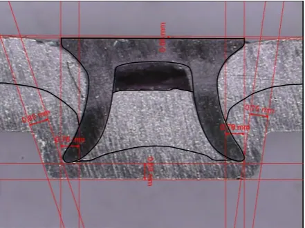
Fig. 5 shows a cross section of the reference SPR joint studied in this paper. The SPR joint quality
attributes have been annotated and these are rivet head height of -0.08 mm, an average interlock of
0.77 mm, and a minimum remaining bottom material thickness of 0.68 mm.
280 mm 23 mm
Bottom sheet
Top sheet 80 mm
48 mm
151.5 mm
Grip area Grip area
[image:9.595.188.409.591.756.2]Figure 5Cross section of a reference (2+2)AA5754 SPR joint with original surface texture and lubricant.
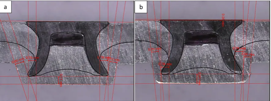
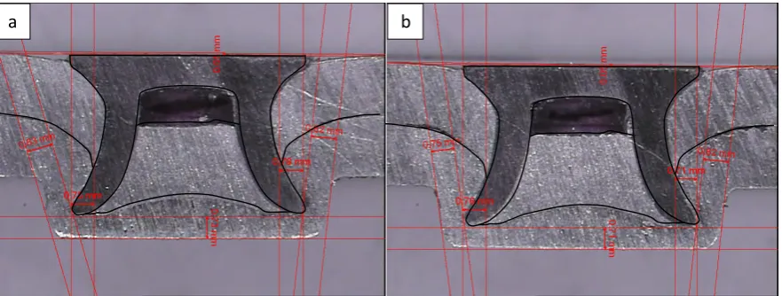
Figure 6Cross section of (2+2)AA5754 SPR joints with the bottom surface of the top sheet impressed by a small ring and garnet particles, a) with particles removed, and b) with particles remained (the black outline is the profile of the deformed rivet and sheet materials in the reference joint).
Fig. 6 shows the cross sections of (2+2)AA5754 SPR joints with the bottom surface of the top
sheet impressed by a small ring with garnet particles. By comparing the cross sections in Figs. 5 and
6, it can be seen that when the local areas were modified by the small ring with or without particles
removed, the rivet head height was getting higher and the interlock and overall Tmin were similar,
although the Tmin to the bottom of the joint button increased. It can be seen that due to increased
friction at ring impression location, the plastic flow of the bottom sheet into the die cavity was getting
more difficult. As a result, more resistance to rivet inserting would be from the bottom material
between the rivet legs and the side of the die and less resistance would be from the material between
the punched top sheet and the bottom of the die, although in this case the influence was not
significant. It can also be seen that for joints with local areas modified by the impression ring, the
cavity under the rivet head and above the punched top sheet became larger compared with the
reference joints, which meant less force was used to push the punched top material into the rivet
cavity.
Figure 7Cross section of (2+2)AA5754 SPR joints with the bottom surface of the top sheet impressed by a medium ring and garnet particles, a) with particles removed, and b) with particles remained.
Figure 8Cross section of (2+2)AA5754 SPR joints with the bottom surface of the top sheet impressed by both small and medium rings and garnet particles, a) with particles removed, and b) with particles remained.
Figs. 7 and 8 show the cross sections of (2+2)AA5754 SPR joints with the bottom surface of the
top sheet impressed by a medium ring and a combination of small and medium rings with garnet
particles, respectively. Similar influence on rivet setting as that for joints with the impression with the
small ring could be seen. The deformation of rivet legs in Fig. 8b was unbalanced, which may be
caused by the slight misalignment of the top and the bottom sheets after ring impression during rivet
inserting. From Figs 6-8, it can be seen that the influence of local surface modification from the
b a
b a
0.0
5
m
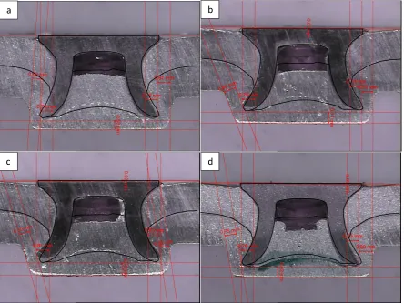
Figure 9Cross section of (2+2)AA5754 SPR joints with the top sheet impressed by a central pin, a), impression only at the bottom surface, b) impression at the bottom surface with particles removed, c) impression at the bottom surface with particles remained, and d) impression only at the top surface.
Fig. 9 shows the cross sections of SPR joints after the top sheet local surface were modified in
different ways. It can be seen that due to the work hardening introduced by the impression, the
punched part of the top sheet had more difficulty to be pushed into the rivet cavity after impression on
the top sheet, leaving larger portion of rivet cavity not filled. In the meantime, for the joints with the
top sheet modified by the central pin and garnet particles, due to the increased friction between the
punched portion of the top sheet and the bottom sheet interface and the mechanical interlocking from
the impression hole, the deformation of the bottom sheet material became more difficult and less
even. From Fig. 9 b and c, it can be seen that when the top sheet was impressed by central pin and
garnet particles, the rivets flared more compared with those in the reference joints resulting in slightly
larger interlocks. From Fig. 9a-c, it can be seen that after impression with the central pin, the punched
b a
the punched portion of the top sheet) but leaving a larger volume not filled between the rivet head and
the punched portion of the top sheet in the joints (judged from the top surface profile of the punched
portion of the top sheet) compared with the reference joint. This meant that the punched portion of the
top sheet was compressed into a smaller volume or had larger compress deformation in the joints with
[image:13.595.66.534.243.745.2]the top sheet impressed by the central pin.
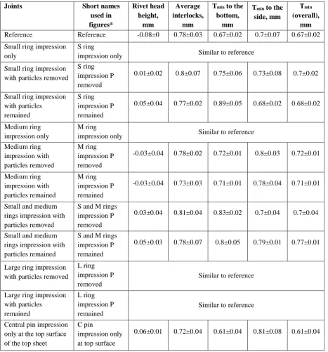
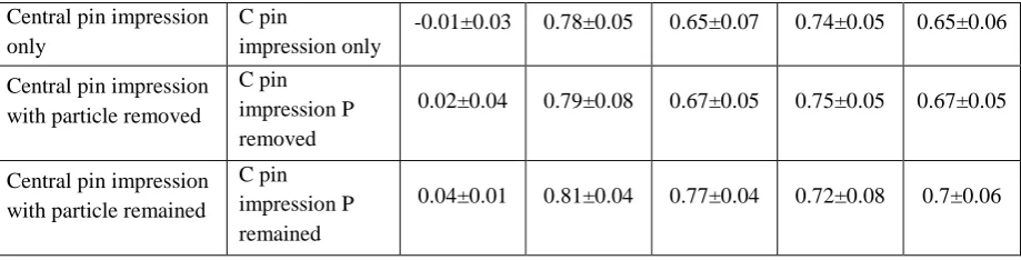
Table 2Summary of selected SPR joint features (All modifications were conducted on the bottom surface of the top sheet unless otherwise stated).
Joints Short names
used in figures* Rivet head height, mm Average interlocks, mm
Tminto the
bottom, mm
Tminto the
side, mm
Tmin
(overall), mm
Reference Reference -0.08±0 0.78±0.03 0.67±0.02 0.7±0.07 0.67±0.02
Small ring impression only
S ring
impression only Similar to reference
Small ring impression with particles removed
S ring impression P removed
0.01±0.02 0.8±0.07 0.75±0.06 0.73±0.08 0.7±0.02
Small ring impression with particles
remained
S ring impression P remained
0.05±0.04 0.77±0.02 0.89±0.05 0.68±0.02 0.68±0.02
Medium ring impression only
M ring
impression only Similar to reference
Medium ring impression with particles removed M ring impression P removed
-0.03±0.04 0.78±0.02 0.72±0.01 0.8±0.03 0.72±0.01
Medium ring impression with particles remained M ring impression P remained
-0.03±0.04 0.73±0.03 0.71±0.01 0.78±0.04 0.71±0.01
Small and medium rings impression with particles removed
S and M rings impression P removed
0.03±0.04 0.81±0.04 0.83±0.02 0.7±0.04 0.7±0.04
Small and medium rings impression with particles remained
S and M rings impression P remained
0.05±0.03 0.78±0.07 0.8±0.05 0.79±0.01 0.77±0.01
Large ring impression with particles removed
L ring impression P removed
Similar to reference
Large ring impression with particles
remained
L ring impression P remained
Central pin impression only
C pin
impression only
-0.01±0.03 0.78±0.05 0.65±0.07 0.74±0.05 0.65±0.06
Central pin impression with particle removed
C pin impression P removed
0.02±0.04 0.79±0.08 0.67±0.05 0.75±0.05 0.67±0.05
Central pin impression with particle remained
C pin impression P remained
0.04±0.01 0.81±0.04 0.77±0.04 0.72±0.08 0.7±0.06
[image:14.595.69.529.71.188.2]* ‘S’,’M’,’L’ mean small, medium and large respectively, ‘C’ means central, and ‘P’ means particles.
Table 2 summarises the joint features of some SPR joints. The joint features for the joints with ring
impression only and with large ring impression were not summarised because they were similar to
those for the reference joints. It can be seen that for all the joints modified by the ring impression the
interlocks had no obvious change; however, the Tminwas slightly increased and the rivet head height
were slightly increased. As to the joints with the top sheet modified with the central pin, when an
impression was applied on the top surface of the top sheet, the rivet head height of the joints increased
and the interlock and the Tminof the joints decreased; when the top sheet was modified on the bottom
surface of the top sheet, the rivet head height of the joints increased, the interlocks slightly increased,
and the Tmin of the joints did not have obvious change but with larger deviations. General speaking,
when the bottom surface of the top sheet was modified with hard particles and with particles removed
afterwards, the rivet head height increase would be larger than that for joints just having impression,
and when the particles was remained in the joints after impression, the rivet head height would be
even higher. Overall, the influence of local surface textures on the joint features was not significant.
3.2. SPR rivet inserting process
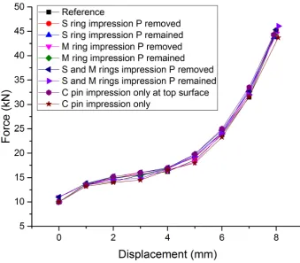
Fig. 10 shows the SPR rivet setting displacement-force curves for joints with and without local
surface modification (except for the central pin modification on the top surface of the top sheet, all
other modifications were on the bottom surface of the top sheet). To avoid the curves to be too messy,
only some representative curves were included. It can be seen that the displacement-force curve for
rivet setting forces were slightly higher between displacements of 2 and 7 mm, this difference was
within the process deviation and overall the influence of local surface modification on the
[image:15.595.121.461.166.463.2]displacement-force curves was not significant.
Figure 10SPR riveting setting displacement-force curves.
3.3. SPR joint static lap shear strength
Fig. 11 presents the quasi-static lap shear strength of various specimens with or without local
surface modification. It can be seen that central pin impression on the top surface of the top sheet did
not change the lap shear strength of the joint; however, central pin impression on the bottom surface
of the top sheet increased the joint strength. Local impression only (without hard particles) with
different size of rings close to the rivet piercing location did not increase the joint strength; however,
joints with the garnet particles were left at the surface after impression the lap shear joint strength was
much higher than that for the joints with the particles removed after impression. When the combined
impression from the small and medium rings were applied, the joint lap shear strength increased
[image:16.595.88.524.189.514.2]slightly further compared with that from the joints with the top sheet impressed by the small ring only.
Figure 11Quasi-static lap shear strength of specimens.
4. Discussion
4.1 Influence of local surface texture on rivet inserting process
From the results in Sections 3.1 and 3.2, it can be seen that different local surface texture through
impression could have some influence on the joint quality and rivet inserting displacement-force
curves, but this influence was not significant. This can be explained through the deformation and
Hou et al. [17] studied the typical four-stage displacement-force curves of SPR rivet inserting
process, and later on Bouchard et al. [18] also used Forge2005® finite element code to model SPR
process for rivetability prediction and compared it with experimental results. Both of the studies
showed that there was a gap formed between the top sheet and the bottom sheet just after the rivet
penetrated the top sheet and started to pierce the bottom sheet when a die with a pip at the bottom was
used, and this gap was closed up during later rivet setting process. Haque et al. [19] studied the
displacement-force curves of self-piercing riveting carbon steels with a flat bottom die. Gaps between
the top and the bottom sheet during rivet inserting process were also reported due to the difference of
material flow. For the material stack and rivet/die combination we studied, a flat bottom die was used
and similarly gaps formed between the top and bottom sheets during the rivet inserting process were
found. Fig. 12 shows the force-displacement curve of the SPR process for the combination studied
with joint cross sections at different rivet inserting stages. It can be seen that from the beginning of
rivet setting, there was a gap between the top and the bottom sheet due to no intimate contact. When
the rivet started to pierce the bottom sheet, the gap between the top and the bottom sheet underneath
the rivet cavity was closed up, but outside the rivet inserting location, and this gap was still existing.
The gap at the location immediately next to the rivet inserting location became larger, due to the
higher degree of bending of the bottom sheet than the top sheet. This gap was not closed up until the
very late stage of the rivet setting process when the rivet head started to contact and apply force to the
top sheet. The largest gap was existing between the clamping locations and the rivet skirt/legs during
Figure 12.The force-displacement curve of the SPR process for the material stack and rivet/die combination with joint cross sections at different rivet inserting stages.
Although during a SPR riveting process, the friction between the top and bottom sheet has some
influence on the inserting force, rivet deformation and joint quality, due to the existing of gaps and no
intimate contact between the top and bottom sheets, especially at the locations with large plastic flow
(between the clamping locations and the rivet skirt/legs), it is believed that the friction between the
top and the bottom sheets outside the rivet penetration location during a riveting process is not large
and have no significant influence on the rivet inserting process and joint quality. As a result, when the
bottom surface of the top sheet was locally modified with different texture outside the rivet
penetration location, it had no significant influence on the joint quality and rivet inserting
displacement-force curves. As to friction during a rivet inserting process, it is believed that the friction
between the rivet and the substrate materials and the friction between the top and the bottom sheets at
other locations, such as between the punched top material and the bottom material, may have more
significant influence on the inserting process. Other factors that influence the rivet inserting
0 5 10 15 20 25 30 35 40 45 50
0 1 2 3 4 5 6 7 8
Fo
rc
e,
kN
displacement-force curves include the mechanical properties of rivet and sheet materials, the
dimensions and geometries of the die and rivet, and the material stack.
4.2 Influence of local surface texture on static lap shear strength
To understand the factors that can influence the static lap shear strength of a SPR joint, it is very
important to understand the mechanical states of the SPR joint during a static lap shear test. Fig. 13
shows some of the critical locations and their mechanical states during a static lap shear test. It can be
seen that there are four critical friction locations: 1 to 4, and two critical compression force locations:
5 and 6, due to the pulling and secondary bending from the top and bottom sheets. Location 1 is at the
interface between the rivet and the top sheet on the tension side: location for main friction when the
rivet head is pulled out of the top sheet; location 2 is at the interface between the rivet and the bottom
sheet on the tension side: location for main friction when the rivet skirt is pulled out of the bottom
sheet; location 3 is at the interface between the top and bottom sheets around the tip of the punched
hole in the top sheet on the tension side: location for main friction between the top and bottom sheets;
location 4 is at the interface between the rivet and the bottom sheet underneath the rivet skirt: friction
location when the rivet is forced to rotate; location 5 is at the interface between the rivet and the top
sheet on the compression side: location for main compression force between the rivet and the top
sheet; location 6 is at the interface between the rivet and the bottom sheet on the compression side:
location for main compression force between the rivet and the bottom sheet. The compression at
locations 5 and 6 was the result of the applied shear forces. There were compressions and relative
movements at the four critical friction locations, and the compressions at these locations could be
from difference sources, such as the residual stress from rivet setting process (residual stress), and the
bending of sheet material (sheet bending) and the rotating of the rivet (rivet rotating) during the lap
shear test. The compression at locations 1 and 2 was from residual stress which has been reported
shear test. Fig. 13 is only a 2D schematic diagram showing the cross section along the central line,
and for 3D concept the locations has to be treated as curved surfaces around that locations. In this
study, for first 11 stacks listed in Table 2, because only the bottom surface of the top sheet was
[image:20.595.147.464.196.416.2]modified, the main factor that would influence the lap shear strength would be related to location 3.
Figure 13Critical locations and their mechanical states during a static lap shear test.
Results from Li et al. [6] pointed out that the friction force between the tip of the punched hole in
the top sheet and the edge of the partially pierced hole in the bottom sheet was very important for
static lap shear strength. Their results showed that fretting during fatigue increased friction force
between the tip of the punched hole in the top sheet and the edge of the partially pierced hole in the
bottom sheet, and as a result the remaining static lap shear strength of the specimens was increased.
One purpose of this research is to prove the importance of this local friction and confirm the critical
locations.
Fig. 14 shows the fracture interfaces of some specimens after lap shear tests. The friction marks on
the fracture interfaces showed that during lap shear tests the main friction between the top and the
bottom sheets was at location 3, at the interface between the top and bottom sheets interface around
F 1 F
2
4
5
6 3
Secondary bending
Secondary bending Rivet
rotating
Rivet rotating
8
Figure 14Fracture interfaces of specimens with local impression on the bottom surface of the top sheet after lap shear tests, a) reference, b) central pin impression with particles remained, c) small ring impression with particle remained, d) small ring impression with particles removed, e) medium ring impression with particle remained, f) medium ring impression with particles removed, g) large ring impression with particle remained, and h) large ring impression with particles removed.
4.2.1 Locations outside the piercing ring
The lap shear results in Fig. 11 show that local surface texture (modified by the impression rings)
close to and outside of the rivet piercing circle could increase the static lap shear strength of the SPR
joints. There are two effects on the substrate when an impression with hard particles is conducted on
the surface: one is work hardening and the other is the increase of surface roughness and subsequently
local friction.
a b
h g
f e
d c
Figure 15Local textures and deformation of the coupons for lap shear specimens after surface modifications, a) small ring impression with particles remained, b) small ring impression with particles removed, c) small ring impression only, d) medium ring impression with particles remained, e) medium ring impression with particles removed, f) small and medium rings impression with particles remained, g) small and medium rings impression with particles removed, h) central pin impression with particles remained, i) central pin impression with particles removed and j) central pin impression only.
Fig. 15 shows local textures and deformation of the coupons for lap shear specimens after
impressions. It can be seen that for coupons impressed with particles and with particles removed
afterwards, the local surface became much rougher (Fig. 15b, e, g and i); for coupons impressed with
particles and with particles remained, some particles were imbedded in the substrate (Fig. 15a, d, f
a b c
h i j
d e
f g
impression mark (mainly from deformed solid wax, Fig. 15c). For joints with local impression only, it
was assumed that only work hardening effect existed since the impression did not increase the local
roughness.
Because the impression marks for all the impression with different size of rings were very shallow,
it is believed that the work hardening to the local bulk material was very small, and as a result the
influence of work hardening on joint strength by ring impression would be very little. This was
confirmed by the insignificant joint strength increase of the joints with local impression only. For
joints with local ring and hard particle impression, it can be assumed that the work hardening to the
local bulk material was similar to that for the joints with local impression only and was not
significant. This means that the main influence of local ring impression on the joint lap shear strength
is from the increase of local friction. It is believed that the local friction would increase with the
increase of roughness. Also, when hard particles were remained in the joints, during rivet inserting
and following lap shear test, the hard particles would penetrate into the mating surface (the top surface
of the bottom sheet that was not modified) as well, which will further increase the friction force at the
local interface. The influence of local friction on joint lap shear strength was confirmed by the results
presented in Fig. 11. It showed that for all the joints with impression with different size of rings and
hard particles, the lap shear strength increased, and the joints with particles remained had further
higher joint strength for the same location of impression modification.
It may be argued that the lap shear strength increase could be caused by different joint features,
especially joint interlocks, but the results in Table 3 showed that the joint features for all the joints did
not have significant difference. On the contrary, when the same impression ring was used, the
interlock distances for the joints with particles remained were slightly lower than those for the joints
with particles removed, although the lap shear strength for the former was higher.
Fig. 14 showed that during lap shear tests the main friction between the top and the bottom sheets was
around the tip of the punched hole in the top sheet on the tension side. Fig. 14 showed that the friction
severity for specimens impressed with different sizes of rings is in the following orders: 1. Small
ring>medium ring>large ring and 2. Impression with particles remained>impression with particles
removed>reference or central pin impression. This is consistent with the increase of the joint lap shear
strength. It worth pointing out that when the sheet surface was modified with local rings and with
particles remained, the remained particles might spread into the area around during riveting and
subsequent lap shear tests. This may be the reason that for the joints with medium ring impression and
with particles remained, the friction at the tip of the punched hole of the top sheet (the area normally
covered by the small ring impression) (Fig.14e) was much severer than the friction for the joints with
medium ring impression and with particles removed (Fig.14f). Fig. 16 shows the optical images of the
friction marks at the bottom surface of the top sheet around the punched hole of the three selected
specimens after lap shear tests. Fig. 16a shows that when the sheet material had the original surface,
after the lap shear test, only some shallow friction marks could be seen at the tip of the punched hole;
Fig. 16b shows that when the sheet material was locally modified by the small ring and with particles
removed, some deep friction marks left at the tip of the punched hole; Fig. 16c shows that when the
sheet material was locally modified by the small ring and with particles remained, the surface at the
tip of the punched hole was worn down and some friction debris left on the surface. The friction
marks in Fig. 16a were about 1.5 mm long, the friction marks in Fig. 16b were about 2.2-2.5 mm long
and the friction marks in Fig. 16c were about 3 mm (not completely covered by the image). This
result together with fracture interfaces in Fig. 14 can confirm that the friction marks were mainly
within the small and medium ring impression areas (between 0 and 3 mm to the edge of the punched
hole). Fig. 16 also showed that the most severe wear on the top sheet was at an area about 0-1.5 mm
Figure 16Multi-focus optical microscope images of the friction marks at the bottom surface of the top sheet around the pierced hole of three selected specimens after lap shear tests, a) reference, b) small ring impression with particles removed, c) small ring impression with particles remained and d) location of the optical images indicated by the rectangle.
The results in Figs. 11 and 14 can also confirm the critical locations of the local friction. Fig. 11
showed that with a single ring impression the largest lap shear strength increase was generated by the
impression with the small ring and with hard particles remained. With the increase of ring size, it can
be seen that the lap shear strength increase compared to the reference specimens was getting smaller.
When the impressions from the small ring and the medium ring were both applied, the lap shear
strength of the joints increased slightly further, compared with the joints with impression from the
small ring only. It can be seen that the critical location for friction influence was at the small ring
impression location, which was a small area next to the rivet piercing site at the top and the bottom
sheet interface. After the joint was formed, the location would be at the top and bottom sheet interface
around the tip of the punched hole in the top sheet. When the location moved further away from the 1 mm
a b
c d
1 mm
1 mm
From Fig. 15, it can be seen that the deformation caused by the ring impression was very small,
and on the contrary, the deformation caused by the central pin impression was large, leaving an
impression hole and a dent around. These different deformations were caused by the different size of
impression heads. For the central pin, the impression area is 8 mm2, and for the small ring, the
impression area is 32 mm2. It is believed that the work hardening caused by the central pin impression
[image:26.595.158.427.244.324.2]was substantial and the work hardening caused by the ring impressions was small.
Figure 17Deformation of SPR rivets during lap shear tests.
The lap shear results in Fig. 11 show that local surface texture (modified by the central pin) in the
centre of the rivet piercing circle could also increase the static lap shear strength of SPR joints. The
results showed that when the pin impression was conducted on the top surface of the top sheet, the
static lap shear strength had no obvious increase, but when the impression was conducted on the
bottom surface of the top sheet, the lap shear strength increase was about 0.5 kN. It can be seen that
increase the local surface roughness by impression with hard particles did not increase the lap shear
strength further. Obviously, if there was friction at this central location during lap shear tests, the
friction force would be increased by the local roughened surface. However, from the fracture interface
of failed lap shear specimens and the mechanical states described in Fig. 13, it was found that during a
lap shear test, due to the secondary bending of the sheet material and the rotating of the rivet, a gap
would be generated between the punched portion of the top sheet and the bottom sheet interface (as
shown in location 8 in Fig. 13). Due to the existing of this gap, no substantial friction would occur at
this location, and as a result increase of the local surface roughness at the pin impression location did
not increase the lap shear strength further. It is believed that the lap shear strength increase for joints
From Fig. 9a-c, it can be seen that compared with the reference joint, in the joints with the bottom
surface of the top sheet impressed by the pin, the punched material from the top sheet had larger total
compression deformation (including the deformation caused by pin impression), and as a result, its
remained volume was smaller and a larger cavity between the rivet head and the punched material
was left. Larger deformation would mean larger work hardening and higher strength for the punched
material. Although the punched material does not play a big role during joint lap shear deformation, it
gives support to the rivet skirt and the deformation of rivet skirt is important to joint strength.
Although rivets are much stronger than the aluminium alloy substrates, evidence showed that they did
deform during lap shear tests, as shown in Fig. 17 (rivet skirt squeezed in one direction). It is believed
that the stronger support from the punched material made the rivet skirt less easy to be squeezed/bent
back, and consequently increased the joint strength. However, when the impression was conducted on
the top surface of the top sheet, the strength of the upper part of the punched material from the top
sheet increased, which would make the punched top material more difficult to be pushed into the rivet
cavity, leaving a larger gap between the rivet head and the top of the punched material, as shown in
Fig. 9d. Since the support of rivet skirt from the lower part was more effective than that from the
upper part against compression, no obvious lap shear strength increase could be seen in this case.
5. Conclusions
To study the influence of local frictions on rivet inserting process, joint features and static lap
shear strength, the surface of the top sheet has been locally modified around the rivet piercing location
with different impression tools and garnet particles. The following conclusions can be drawn:
1) The studied local surface textures on the aluminium sheet did not have significant influence
on the rivet inserting process based on displacement-force curve analysis.
3) The lap shear tests showed that ring impressions with garnet particles and central pin
impressions on the bottom surface of the top sheet increased the static lap shear strength of
the SPR joints. The strength improvement from local ring impressions with particles was by
increasing local friction and the strength improvement from central pin impressions was by
local work-hardening.
4) It was confirmed that the critical location for local friction influence on the lap shear strength
was around the rivet leg piercing location or in other words around the tip of the punched hole
in the top sheet after rivet inserting.
Acknowledgement
The authors would like to thanks Innovate UK for the support of this research through HVM
Catapult. The authors would also like to thanks Henrob Ltd for providing the rivets for this research.
References
[1] Li D, Chrysanthou A, Patel I, Williams G, Self-piercing riveting-a review, Int J Adv Manuf Tech, 2017, doi:10.1007/s00170-017-0156-x.
[2] Chapter 33 Bolted connections-I, www.steel-insdag.org/TeachingMaterial/chapter33.pdf; 2000 [accessed 20.06.17].
[3] Bolted Joint Design - Fastenal, https://www.fastenal.com/content/feds/pdf/Article%20-%20Bolted%20Joint%20Design.pdf; 2009 [accessed 20.06.17].
[4] Han L, Chrysanthou A, Evaluation of quality and behaviour of self-piercing riveted aluminium to high strength low alloy sheets with different surface coatings, Mater Design, 2008; 29: 458-68. [5] Han L, Chrysanthou A, O'Sullivan JM, Fretting behaviour of self-piercing riveted aluminium alloy joints under different interfacial conditions, Mater Design, 2006; 27: 200-8.
[6] Li D, Han L, Thornton M, Shergold M, Williams G, The influence of fatigue on the stiffness and remaining static strength of self-piercing riveted aluminium joints, Mater Design, 2014; 54: 301-14. [7] Han L, Young KW, Hewitt R, Alkahari MR, Chrysanthou A, Effect of sheet material coatings on quality and strength of self-piercing riveted joints, in: SAE World Congress, Paper No. 2006-01-0775, 2006.
[8] Xu Y, A close look at self-piercing riveting-Computer simulation is a noteworthy alternative to physical testing of joints, in: The Fabricator, 2006.
[9] Khezri R, Sjöström E, Melander A, Self-piercing riveting of high strength steel, in: Swedish Institute for Metal Research, Report No. IM-2000-554, 2000.
[10] Abe Y, Kato T, Mori K, Self-piercing riveting of high tensile strength steel and aluminium alloy sheets using conventional rivet and die, J Mater Process Tech, 2009; 209: 3914-22.
[12] Atzeni E, Ippolito R, Settineri L, Experimental and numerical appraisal of self-piercing riveting, CIRP Ann Manuf Technol, 2009; 58: 17-20.
[13] Carandente M, Dashwood RJ, Masters IG, Han L, Improvements in numerical simulation of the SPR process using a thermo-mechanical finite element analysis, J Mater Process Tech, 2016; 236: 148-61.
[14] Han SL, Tang XD, Gao Y, Zeng QL, Effects of friction factors on flat bottom self-pierce riveting joints of AZ31 magnesium alloy, Mater Res Innov, 2015; 19: S10-235-38.
[15] Li D, Han L, Thornton M, Shergold M, Influence of edge distance on quality and static behaviour of self-piercing riveted aluminium joints, Mater Design, 2012; 34: 22-31.
[16] Li D, Han L, Thornton M, Shergold M, Influence of rivet to sheet edge distance on fatigue strength of self-piercing riveted aluminium joints, Mat Sci Eng A-Struct, 2012; 558: 242-252.
[17] Hou W, Mangialardi E, Hu SJ, Wang PC, Menassa R, Characterization for Quality Monitoring of a Self-Piercing Riveting, in: Sheet Metal Welding conference XI, Sterling Heights, Michigan, 2004, Paper No. 8-3.
[18] Bouchard PO, Laurent T, Tollier L, Numerical modeling of self-pierce riveting-From riveting process modeling down to structural analysis, J Mater Process Tech, 2008; 202: 290-300.
[19] Haque R, Beynon JH, Durandet Y, Characterisation of force-displacement curve in self-pierce riveting, Sci Technol Weld Joi, 2012; 17: 476-88.
[20] Huang L, Moraes JFC, Sediako DG, Jordon JB, Guo H, Su X, Finite-Element and Residual Stress Analysis of Self-Pierce Riveting in Dissimilar Metal Sheets, J Manuf Sci E T ASME, 2017; 139: 021007-1 - 021007-1021007-1.
[21] Haque R, Wong YC, Paradowska A, Blacket S, Durandet Y, SPR Characteristics Curve and Distribution of Residual Stress in Self-Piercing Riveted Joints of Steel Sheets, Adv Mater Sci Eng, 2017, doi:10.1155/2017/5824171.
[22] Han L, Chrysanthou A, Young KW, Mechanical behaviour of self-piercing riveted multi-layer joints under different specimen configurations, Mater Design, 2007; 28: 2024-33.
[23] Haque R, Wong YC, Paradowska A, Durandet Y, Residual stress profiles in riveted joints of steel sheets, Sci Technol Weld Joi, 2015; 20: 199-207.