Smart and Secure Appliance System
Sara Raad Qasim
M.Sc. Computer and Control Engineering Al-Farabi University, Iraq
ABSTRACT
Security is very important factor nowadays. Every person in the world wants his home, industry or bank to be secured. Home security is becoming very necessary now days as the intrusion possibilities are increasing. In this paper, smart system appliance has been designed that has a special feature which always makes a contact with the owner of the house each time that his/her house has been hacked or risky. Arduino card was used, which is considered as the main microcontroller. This paper aims to develop a prototype of a smart security system using RFID system (Radio frequency identification) to lock home doors, thus achieving a simple home security system. A GSM board (Global System for Mobile) also is used for more security and reliability. When the person allowed to enter the house then the house's devices will operate automatically thus the proposed model provide secure and smart house application.
RFID system continuously transmits its data to Arduino Uno board which act as microcontroller unit. If the person has the right card, then he will be able to enter the house whereas the person with the wrong card will be denied. A message will be send to the owner about the stranger person.
If the owner lost its card then he/she will be able to open/close the house by sending messages to the GSM system.
Keywords
RFID, GSM, Arduino Uno.
1.
INTRODUCTION
In day to day life, home security is very important issue in these days. Security is very important concern everywhere and for everyone. Every person wants his home to be secured. This paper describes a security system project that can keep an industry & home safe. This is a useful and simple security system. Here, the proposed model uses Arduino as its main controller to detect the presence of the unauthorized persons and immediately the system alert is given to alarm others. This system operates using owner's mobile phone with the help of GSM technology. The GSM system is connected with the cellular phone through sending an SMS message only when the microcontroller commands it to do so. The microcontroller receives its information and data from the RFID system.
2.
SYSTEM ARCHITECTURE
[image:1.595.329.521.445.584.2]Figure 1 shows the block diagram of home security prototype. The proposed model contains two units. The microcontroller unit consists of Arduino Uno and the RFID system. The information from the RFID continuously processed by the microcontroller and a command is given to the owner's mobile phone via GSM if someone tries to access the door's house illegally.
Figure 1 Block diagram of the proposed model
2.1
Hardware used
a) Arduino Uno
b) RFID
c) Servo Motor
d) Relays
e) LEDs
f) Fan
g) Buzzer
h) GSM SIM900
Arduino Uno
Arduino is open source prototyping platform based on flexible easy to use hardware and software. Uno is one of the most popular types of Arduino and most commonly used based on the ATmega328 type (evidence form for this controlling), plate Arduino Uno (“Uno” means one in Italian and is named
to mark the upcoming release of Arduino 1.0) containing 14 digital port (input / output) (6 can be used as outlets control symmetrically accidental pulse - PWM outputs. Uno panel also provides 6 analog inputs. In addition a USB port that can be supplied it with the power supply and another port to provide the Arduino Uno with a separate external card (such as the 9-volt batteries)[3][4].
Figure 2 Arduino UNO
RFID
[image:1.595.60.277.710.748.2]Figure 3 RFID System
Servomotor
A servomotor is a rotary actuator or linear actuator that allows for precise control of angular or linear position, velocity and acceleration. It consists of a suitable motor coupled to a sensor for position feedback. It also requires a relatively sophisticated controller.
[image:2.595.343.518.177.294.2]Servomotors are not a specific class of motor although the term servomotor is often used to refer to a motor suitable for use in a closed-loop control system. It is equipped with an electronic circuit to control the direction and position of the column of the mater and is also equipped with a set of gears (shown in Figure 4) [14].
Figure 4 Servo Motor
Relay
It is a device with a width not exceeding 20 millimeters. Its function is to control a high-voltage electric circuit by sending a constant current with low voltages up to 5 or 12 volts (depending on the type of reel). For example, when the control circuit (low voltage) gives a continuous electric current, the electrical circuit connected to the high-voltage relay becomes connected. Consequently, the Relay enabled device is operational[9].
Figure 5 Relay
LEDs
[image:2.595.346.511.398.560.2]A light-emitting diode (LED) is a two-lead semiconductor light source. It is a p–n junction diode that emits light when activated. When a suitable current is applied to the leads, electrons are able to recombine with electron holes within the device, releasing energy in the form of photons. This effect is called electroluminescence, and the color of the light (corresponding to the energy of the photon) is determined by the energy band gap of the semiconductor [12].
Figure 6 LEDs
Fan
A fan is a powered machine used to create flow within a fluid, typically a gas such as air. A fan consists of a rotating arrangement of vanes or blades which act on the air. The rotating assembly of blades and hub is known as a rotor, or a runner. Usually, it is contained within some form of housing. It produces air flows with high volume and low pressure. Most fans are powered by electric motors [11].
Figure 7 5 volt Fan
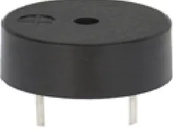
Buzzer
A device that converts electrical energy to audible sound, which is used for voice notification in cars and microwaves, operates on a typical stage on a 6-12 volt voltage and a constant current of about 25 mA[8].
[image:2.595.65.267.427.530.2] [image:2.595.370.497.644.742.2] [image:2.595.72.267.654.700.2]GSM
SIM900A
GSM (Global System for Mobile Communications) is a standard developed by the European Telecommunications Standards Institute (ETSI) to describe the protocols for second-generation digital cellular networks used by mobile devices such as tablets[6].
[image:3.595.321.535.218.407.2]The SIM900A is a complete Dual-band GSM/GPRS module in an SMT (Surface-mount technology) type. Is small and cost-effective, which features an RS232 interface, allows connection to PC as well as a microcontroller with RS232 Chip(MAX232), Input Voltage of 12V DC, with a configurable baud rate ranging from 9600-115200 through AT commands. SIM900A is low power consumption for GSM/GPRS with 900 to 1800MHz[7].
Figure 9 GSM SIM900A
The GSM shield is particularly useful as it allows to:
Connect to the Internet over GPRS network
Send and receive SMS
Place and receive phones calls
These capabilities make it perfect for interacts with Arduino in this project.
2.2
Working Circuit and Software Design
The system is in deactivated mode initially. It is activated by two cases:
When a visitor try to access the house by putting its card near the RFID reader (which is settled on the house door) then if the visitor has the correct card then the door will be opened normally and the house will be lighten and a fan will be operated automatically. Whereas if the person has the incorrect card then he is a stranger so the buzzer alert and red LED will be on, and the Arduino will be alarmed through the RFID system. Arduino will immediately send a particular command to GSM system which will react by sending an SMS to the house owner.
1. If the owner lost its card or need to allow a known person to enter the house without a card then this can be done when the owner sends a message to the GSM which will command the Arduino to achieve this goal.
Software requirement (Arduino
Environment)
Arduino 1.6.1 environment is the open source software (IDE) makes it easy to write codes and upload it on the microcontroller board. It runs on various platforms like windows, mac OS and Linux. The environment is written in Java and based on other open source software. Arduino programs are written in C / C++.
The overall flow diagram of the proposed model is shown in Figure 10, where it is assumed that the user already set up the hardware and software for the system activation and the mobile address for GSM communications.
Figure 10 Flowchart of the proposed smart system
The program and its details are as follow:
#include <SPI.h>
#include <MFRC522.h>
#include <Servo.h>
#include <SoftwareSerial.h>;
SoftwareSerial SIM900(7, 8);
#define SS_PIN 10
#define RST_PIN 9
MFRC522 mfrc522(SS_PIN, RST_PIN); // Create MFRC522 instance.
const int l1 = 1; // The red led pin
const int relay2 = 2; // The led pin
const int relay3 = 3; // The fan pin
int servopin=0; // servo
int buzz=4;
Servo servo;
int angle=120;
char incoming_char=0;
int s = 0;
void setup()
[image:3.595.64.263.250.411.2]Serial.begin(9600); // Initiate a serial communication
SPI.begin(); // Initiate SPI bus
mfrc522.PCD_Init(); // Initiate MFRC522
SIM900.begin(9600);
delay(5000);
Serial.println("OK");
Serial.println();
servo.write(angle);
pinMode(l1, OUTPUT); // enable red led pin for output
pinMode(relay2, OUTPUT); // enable led pin for output
pinMode(relay3, OUTPUT); // enable the fan pin for output
pinMode(buzz, OUTPUT); // enable the pin for output}
void set(){
SIM900.println("ATD 33XXXXXXXX;"); //Celular
delay(100);
SIM900.println();
delay(10000); // wait for 10 seconds...
SIM900.println("ATH");
delay(1000);}
void send_sms(){
SIM900.print("AT+CMGF=1\r"); // AT command to send SMS message
delay(100);
SIM900.println("AT+CMGS=\"+xxowner numberxx\"");
delay(100);
SIM900.println("Warning : invalid card"); // message to send
delay(100);
SIM900.println((char)26); // End AT command with a ^Z, ASCII code 26
delay(100);
SIM900.println();
delay(5000);
Serial.println("Warning : invalid card");
Serial.println("SMS sent successfully");}
void read_msg(){
s = 1;
while(s==1){
if(SIM900.available()>0){
incoming_char=SIM900.read(); //Get the character from the cellular serial port.
Serial.print(incoming_char); //Print the incoming character to the terminal.
s = 0;}}}
void mode_rec_msg(){
SIM900.print("AT+CMGF=1\r"); // set SMS mode to text
delay(100);
SIM900.print("AT+CNMI=2,2,0,0,0\r");
// blurt out contents of new SMS upon receipt to the GSM shield's serial out
delay(1000);}
void loop() {
// Look for new cards
if ( ! mfrc522.PICC_IsNewCardPresent()) {
return;}
// Select one of the cards
if ( ! mfrc522.PICC_ReadCardSerial()) {return;}
/Show UID on serial monitor
Serial.print("UID tag :");
String content= "";
byte letter;
for (byte i = 0; i < mfrc522.uid.size; i++) {
Serial.print(mfrc522.uid.uidByte[i] < 0x10 ? " 0" : " ");
Serial.print(mfrc522.uid.uidByte[i], HEX);
content.concat(String(mfrc522.uid.uidByte[i] < 0x10 ? " 0": " "));
content.concat(String(mfrc522.uid.uidByte[i], HEX)); }
Serial.println();
Serial.print("Message : "); content.toUpperCase();
if (content.substring(1) == "78 B3 52 10") //give access the correct card
if(angle==120) // the authorized user entering the house so door closed and devices off
{ digitalWrite(relay3, HIGH); // Turn on fan and led
digitalWrite(relay2, HIGH);
digitalWrite(buzz, LOW); // alarm system off
digitalWrite(l1, LOW); servo.write(0); // open the door
Serial.println(); delay(3000);
angle=0; } else if (angle==0) // the authorized user leaving the house so door closed and devices off {
digitalWrite(relay3, LOW); // Turn off fan and led
digitalWrite(relay2, LOW);
digitalWrite(buzz, LOW); // alarm system off
digitalWrite(l1, LOW);
servo.write(120); // close the door
Serial.println();
delay(3000);
else if (content.substring(1) == "95 57 CE 65") //do not give access the incorrect card set(); send_sms(); // send SMS to the house owner
digitalWrite(relay3, LOW); // Do not turn fan and led on
digitalWrite(relay2, LOW);
digitalWrite(buzz, HIGH); // alarm system on
digitalWrite(l1, HIGH);
delay(3000); set();
mode_rec_msg();
for(;;){
if(SIM900.available()>0)
incoming_char=SIM900.read(); //Get the character from the cellular serial port.
Serial.print(incoming_char); //Print the incoming character to the terminal.}
if(Serial.available()>0){
if(Serial.read() == 'A') break;
if(Serial.read() == 'open') {
digitalWrite(relay3, HIGH); // Turn on fan and led
digitalWrite(relay2, HIGH);
digitalWrite(buzz, LOW); // alarm system off
digitalWrite(l1, LOW);
servo.write(0); // open the door
Serial.println();
delay(3000);}
if(Serial.read() == 'close') {
digitalWrite(relay3, LOW); // Turn off fan and led
digitalWrite(relay2, LOW);
digitalWrite(buzz, LOW); // alarm system off
digitalWrite(l1, LOW);
servo.write(120); // close the door
Serial.println();
delay(3000);}}
Serial.println("OK-2");
delay(100);
SIM900.println();
delay(30000);
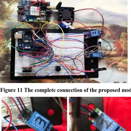
while(1)
[image:5.595.317.531.78.291.2]The complete connection is shown in Figure 11. Figure 12 shows the Relays connections. Relay 2 is connected with the LED which represents the house light whereas the Relay 3 is connected with the fan.
Figure 11 The complete connection of the proposed model
Figure 12 Relay 2 and 3 connection
3.
FUTURE SCOPE
For more security purpose camera module can also be implemented on the system. If any person attempt to enter in home with more than three time wrong card then at that time camera module will be activated and capture the image of person who trying to attack on system. Also a more sensors like a magnetic sensor can be used to prevent any person from breaks the window and enter the house.
4.
CONCLUSION
In this paper, a novel architecture for flexible and smart home security and application using Arduino microcontroller is proposed and implemented.
The important of home security measures are built using easily available programmable components such as RFID and GSM systems; by implementing this type of system we can secure entry point of our home and banks in very easy way.
5.
REFERENCES
[1] R. Sharma, C. P. katara, V. Shankar “Proceedings of IEEE TechSym 2014 Satellite Conference VIT University, Paper on Advanced Low-Cost Security system using sensors Arduino and GSM communication module.”
[2] Q. Qu, Z. Guohao, W. Baohua, “Design of Home Safeguard System Based on GSM Technique.” Electronic Engineer, bol. 32, no. II pp. 76-78, Nov. 2006
[3] Arduino Uno datasheet available online at https://components101.com/microcontrollers/arduin o-uno
[4] https://www.farnell.com/datasheets/1682209 [5] https://www.sparkfun.com/products/13975
[6] GSM datasheet available online at https://randomnerdtutorials.com/sim900-gsm-gprs-shield-arduino
[7] Simcom GSM modem
[8] Buzzer datasheet available online at https://components101.com/buzzer-pinout-working-datasheet
[9] Relay datasheet available online at https://randomnerdtutorials.com/guide-for-relay-module-with-arduino
[10]A. A. Zandamela, "An Approach to Smart Home Security System Using Arduino." Electrical Engineering: An International Journal (EEIJ), Vol. 4, No. 2/3, September 2017.
[11]Fan datasheet available online at https://en.wikipedia.org/wiki/Fan_(machine) [12]LED datasheet available online at
https://en.wikipedia.org/wiki/Light-emitting_diode [13]RFID datasheet available online at
http://www.technovelgy.com/ct/technology-article.asp
[14]Servomotor datasheet available online at https://en.wikipedia.org/wiki/Servomotor
[15]M.L.Sharma, S.Kumar , N.Mehta, "Smart Home System Using IOT." International Research Journal of Engineering and Technology (IRJET), Vol. 04, Issue 11, Nov -2017.