RAID-based Storage Systems
Saleh A. Khawatreh
Al-Ahliyya Amman University, Faculty of Engineering
,
Computer Engineering Dept.Nidhal Kamel Taha El-Omari
WISE University, Faculty of Information Technology Amman, Jordan
ABSTRACT
With the exponential growth in computing and microprocessor technology, it is natural to expect that secondary storage technology must also take steps to keep up in improving performance and enhancing reliability with the fundamental need. Redundant array of independent disks (RAID), based on the magnetic disk technology, is a widely used tactic for data storage that enables greater levels of performance and/or good fault tolerance for protecting against the disk failure.
RAID core concept is cycling around combining together a group of real hard disks into a single storage system where they work collaboratively as a single logical entity and the failure of one of them is not quite harm.
In this research, the different types of RAID will be presented and a comparison will be made between them.
Keywords
Redundant Array of Inexpensive Disks (RAID), Redundant Array of Independent Disks (RAID), Error-correcting code (ECC), Mirroring, Shadowing, Disk Striping, Just a Bunch of Disks (JBOD), Just a Bunch of Drives (JBOD).
1.
INTRODUCTION
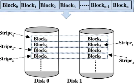
RAID was originally stood for Redundant Arrays of Inexpensive Disks [1], [2], [3], [4]. Lately, it stands for Redundant Array of Independent by letting the "I" in RAID to stand for Independent instead of "Inexpensive" [1].The basic idea behind RAID is to connect multiple independent physical disk array, or group, together to provide large storage capacity, faster access to reading data, redundant data and, in turn, greater levels of high performance and/or fault tolerance [1], [4], [5], [6]. There are many different levels of RAID systems, these levels provide different ranks of redundancy, error checking, capacity, and cost [6]. All of these levels are cycling around dividing the available storage space into computer-generated volumes and storing them in volumes in distributive manner among multiple nodes. These volumes are blocks and the Input/output operations are performed at block-level instead of disk-block-level. Absolutely, rebuilding the lost information at block-level takes lesser time to perform as opposed to disk-level [1], [2], [4], [5], [6]. As depicted in Figure 1, RAID technology could be achieved by allowing reading data in parallel fashion
[image:1.595.321.546.199.305.2]and making the clone of data to be mapped into two or more disk drives [5], [10]. In order to speed up the transfer process, there is a need to reserve several buffers in the main memory [12]. Furthermore, and in order to reduce the average block access time of the successive disk blocks, double buffering can be used [1], [11].
Fig 1: Mapping the data file into different disks.
To explore further the aforementioned arguments, this paper consists of six sections. Section 1 elaborates what RAID technology actually is. Section 2 describes how the striping and mirroring are achieved in RAID. Section 3 defines the RAID organizations and then state the essential characteristics of the most used models. Section 4 investigates the Software-Based RAID technology. The distinction between RAID and Back-up is discussed in Section 5. Without this comparison, both concepts may be seen as the same computing physiologies under different names. The final section, Section 6, concludes this paper and highlights new avenues for further research in this area.
2.
STRIPING AND MIRRORING
Disk-striping (the name is stripe) technique is the process of segmenting the data into blocks, and then each one of them is writtenin a specific pattern across two or more independent consecutive physical storage devices rather than one single device.Normally, blocks are varied from 32KB to 128KB in size [14].
These devices are regularly disk drives, but they may be or tapes. Every segment may be one or more blocks and any each segment should be placed on a distinct physical storage device [1], [3], [4], [6], [11].
Mirroring or shadowing is a disk data redundancy technique, used to solve the problem of reliability (i.e. fault tolerance). It is, as their name suggests, achieved by recording the same data redundantly on two or more identical physical disks that are preserved for this purpose [1], [3], [4], [6].
These physical disks are actually treated as one logical disk [1], [4]. If a disk fails or becomes inaccessible, the other identical disks are used instead until the corrupted disk is repaired or replaced by another one and, in turn, data loss resulting from a physical disk failure can be excluded [6].
As this solution gives good error recovery, whenever some data is lost we can retrieve it from the other source disks. The good thing is that we can read data from more than one disk in parallel and, as a consequence, the read performance is enhanced. On the other hand, since we have to write data into
Disk 0
Disk 1 Disk 2
Disk Block1
to two or more different spots, the recording performance may be slow [3], [4], [12], [14].
Another depressing thing relating to this technique is that it is expensive. It requires twice as many disks as the original ones.
Other techniques can be achieved by storing some extra information that can be used to recover the lost information in case of disk failure [1], [14].
3.
RAID ORGANIZATIONS AND
LEVELS
In this section, the formal RAID levels and how the redundancy is the driving force behind all these levels will be demonstrated. However, each one of them has its benefits and drawbacks that define which one to go with and which one is to ignore.
3.1
RAID Level-0
This type is often known as “data striping” where each drive storage is divided into blocks, called stripes or segments, of data [5], [10], [12]. These blocks of data are fairly distributed in a repeated sequential manner across two or more different disk drives in the system [3], [4], [10].
Since updates do not have to be duplicated, RAID-0 has the best recording performance [1]. While this type is simple to implement, it provides no redundancy of data or error detection and, in turn, this level is not a real RAID level at all [8], [11], [12]. To tell the truth, since no redundancy, all data is gone if any drive fails for any reason despite that a single drive failure has no impact on the data of the other drive(s) [8], [12]. This is why this level is referred to as (AID Level-0) instead of as (RAID Level-0). In consequence, due of no fault-tolerant, this level is not convenient for mission-critical systems [1], [5], [12].
This type is best supported in Windows, OS X as well as Linux [8]. Figure 2 illustrates how this type is recognized by breaking up data sequentially into smaller blocks and stripes these blocks of data into three different disk drives.
As depicted in this Figure, the symbols Block 0, Block1, Block2, Block3, Block4 …etc., are the ordered blocks read if read sequentially from the beginning to the end. As a result, the odd blocks are written to the left disk, disk 0, and the even blocks are written to the right disk, disk 1 [3], [4], [5], [11].
Table 1 summarized how the first 28 blocks of RAID-0 are striped across a 4-disk array using seven stripes. The symbols "B" and "S" in this table stand for block and stripe, respectively.
[image:2.595.319.525.79.189.2]Fig 2: RAID Level-0 (Disk-striping technique)
Table 1: Full-stripe of 5-disk array in RAID Level-0 Stripe # Disk0 Disk1 Disk2 Disk3
S0 B0 B1 B2 B3
S1 B4 B5 B6 B7
S2 B8 B9 B10 B11
S3 B12 B13 B14 B15
S4 B16 B17 B18 B19
S5 B20 B21 B22 B23
S6 B24 B25 B26 B27
3.2
RAID Level-1 (Mirroring)
[image:2.595.319.537.344.478.2]In this type a complete data file is stored on a single physical disk and a second mirrored disk is used to hold an exact copy of the same original file and, in turn, the data is always identical on all disk drives [1], [5], [6], [12], [14]. Moreover, when the first two disk drives are full, the disk drives can be added in pairs and, obviously, both drives contain the same data at all times and the data is resilient to individual disk failures [5], [12], [14]. This type is depicted in Figure 3. Again, this style is also known as “drive mirroring”. Consequently, if one disk drive fails, you do not miss the whole data [5]. For the reason that it provides 100 percent data redundancy, this mirroring, in practice, offers data reliability and marginally higher performance [5], [6], [12], [14].
Fig 3: Block Pattern of RAID Level-1
Despite that the data file can be read in parallel, the write performance suffers from writing out the same piece of data simultaneously twice across the two pairs of RAID drives (one pair for storage, and the other for backup) [3], [4].
As compared with RAID Level-0, twice as many disks are required to store the same data. Since array of disks continues to operate so long as at least one drive is functioning, the reliability is higher than the Level-0 [1], [3], [4], [5]
Again, similar to mirroring, it doubles disk Costs because it requires twice as much storage space [6].
3.3
RAID Level-2 and Level-3
RAID Level-2 is similar to RAID Level-0 but there is a major difference between them [3], [4]. Data is block interleaved in the level-0, but it is bit interleaved in Level-2 and because of that it uses the scheme of Error-correcting code (ECC) to monitor correctness of information on disk [4]. Figure 4 shows how the data is segmented up sequentially into smaller blocks, parity checks are calculated, and then the blocks of data and parity are stored. Furthermore, and as depicted in this Figure, whenever an error occurs in any disk, a parity disk is then used to reconstruct the lost or corrupted data.
Level-2 could be more advantageous than Level-1 especially in the error correction/recovery. But, it may have some performance issues. In case of reading, there is a need to read
Disk Disk 1
Block0 Block1 Block2 Block3 Block4
Block0 Block1 Block2 Block3 Block4 Block1
Block0 Block2 Block3 ….. Blockn-1Blockn
Block0 Block2 Block4 Block6
Block1 Block3 Block5 Block7
Disk 0 Disk 1 Block1
Block0 Block2 Block3 …..Blockn-1 Blockn
Stripe0
Stripe1 Stripe2
[image:2.595.56.273.613.746.2]data plus ECC code from the Check disks. There is however another situation in case of writing where numerous write requests can happen at the same time. We should have to modify data, Check disks, and also the parity disks [3], [4], [5].
[image:3.595.328.526.79.298.2]Another concerning thing is that, we can’t make more than one read at a time from multiple files. This is because of the bit-interleaved placement of data. However, this is another significant issue that needs to be tackled.
Fig 4: Block Pattern of RAID Level-2
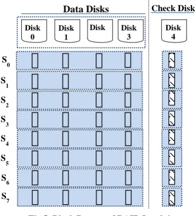
In order to remove the limitations and to support the parallel reading process with some additional features, the next technology, namely RAID Level-3, comes into action [3,4]. This level stripes data across multiple disk drives and an additional one drive is preserved for parity checks. It uses the modern disks that have ECC codes with each sector to tell us whenever a sector is bad and correct it automatically by using the parity disk to refactor the missing data from the remaining physical disk drives.
3.4
RAID Level-4 and Level-5 (Striping
with parity)
To solve the parallel drawback of Level-2 and Level-3, the next technology, namely RAID Level-4 comes in the picture [1], [2], [3]. Due to the exponential growth in the processor and memory speeds, it performs multiple reads at parallel and, therefore, the reading is now faster than before [1], [2]. Figure 5 is schematic diagram for a 5-disk array of this level where the symbol "S" stands for stripe whereby the blocks in the same row are referred to as a stripe; for example, S0, S1, S2, S3, S4, S5, S6, and S7 are the first eight stripes [11]. Table 2 summarized the first 32 blocks of RAID-4, the parities, and the eight stripes. The symbols "S", "B", and "P" in this table stand for stripe, block, and parity, respectively.
[image:3.595.57.282.186.304.2]Because of calculating and writing the parity blocks involves heavy parity calculations by the RAID controller, this level is still comparatively very slow [3].
Fig 5: Block Pattern of RAID Level-4
Table 2: Full-stripe of 5-disk array in RAID Level-4
Stripe # Disk0 Disk1 Disk2 Disk3 Disk4
S0 B0 B1 B2 B3 P0
S1 B4 B5 B6 B7 P1
S2 B8 B9 B10 B11 P2
S3 B12 B13 B14 B15 P3
S4 B16 B17 B18 B19 P4
S5 B20 B21 B22 B23 P5
S6 B24 B25 B26 B27 P6
S7 B28 B29 B30 B31 P7
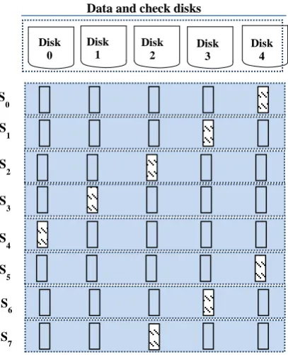
This necessitates the development of the next technology, namely RAID Level-5 where the “Distributed parity and check information” are the key words here. As depicted in Figure 6, the attractive idea behind this technology, RAID-5, is instead of concentrated the check data into a single disk, as in the case of RAID-4, it is distributed among the other physical disk drives. Thus, it is block-level striping with parity distributed among disks. Table 3 summarized the first 32 blocks of RAID-5 and how the parities are rotated across a 5-disk array with eight stripes. The symbols "B" and "P" in this table stand for block and parity, respectively. If a particular drive fails or becomes inaccessible, it can be reconstructed by using the parity information distributed on the remaining drives [12]. Furthermore, at least three drives are required to implement RAID-4 or RAID-5 where the capacity of one single disk drive is reserved to keep fault tolerance [2], [5], [10], [11], [12].
Next, the parity-disk bottleneck for RAID-4 is solved by using the Rotated Parity with RAID-5 [11]. RAID5 can endure one and only one-member disk failure [12]. Whenever a disk drive is corrupted, the subsequent reading can be calculated for the meantime by the use of the distributed check information [1], [2], [3], [12]. Later, all data on this failing disk will be rebuilt and stored onto a spare disk drive that is reserved for this purpose. Thus, the original failing disk will be replaced by the rebuilt disk.
Disk 0
Disk 1
Disk Disk 3
Disk 4
Data Disks Check Disk
S
0
S
1
S
2
S
3
S
4
S
5
S
6
S
7
Block1
Block0 Block2 Block3
Data Disk 0
Data Disk 1
ECC Disk 2
2Parity Disk
4 ECC
Disk 3
Blockn
…..Blockn-1
[image:3.595.316.542.315.423.2]Fig 6: RAID Level-5 is evolved out of RAID Level-4
As RAID Level-5 is evolved out of RAID Level-4, it, however, slightly improves the read requests. But, it offers a way of improving the performance challenge of multiple writes using the parallel techniques more optimally [2], [5], [6], [10].
Table 3: Full-stripe of 5-disk array in RAID Level-5
Stripe # Disk0 Disk1 Disk2 Disk3 Disk4
S0 B0 B1 B2 B3 P0
S1 B5 B6 B7 P1 B4
S2 B10 B11 P2 B8 B9
S3 B15 P3 B12 B13 B14
S4 P4 B16 B17 B18 B19
S5 B20 B21 B22 B23 P5
S6 B25 B26 B27 P6 B24
S7 B30 B31 P7 B28 B29
Moreover, the good thing is that RAID 5 is considered the most common secure RAID level in the aforementioned levels [8]. Finally, to conclude the discussion of this section, these two RAID levels, Level-4 and Level-5, are formally called as “parity-based redundancy” [11] and they have need of at least three disk drives but could work with up to 16 [12].
3.5
RAID Level-6 (Striping with double
parity)
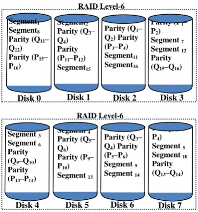
In essence, RAID Level-6 is similar to RAID 5 by using disk striping and parity distributing to all drives, but different by using two independent parity blocks per stripe as an alternative of one [5], [10], [12], [14].
As it uses double parity, this Level is coming into action to offer more data integrity by using dual-parity schemes [3], [5]. Coupled with the beforehand advantage, there are more other perceived benefits that provide the momentum for this level [5], [12], [14]:
Data redundancy and dual-parity leads to high level of data protection. In turn, this level is used for the sensitive data that requires a very high level of protection from loss from loss from loss. While at least four drives are required to
implement this level, this level can fortunately withstand the loss of two drives dying simultaneously without losing any data. This is a good indication that the data can stay living and survive with the losing of one third disk drives. High read rates: this is because data is spread across more
than one disk drive.
Good performance: especially for the environments that implement a lot of small input/output transactions.
Nevertheless, it has a longer write time than RAID Level-5 [3]. This is due to numerous write requests that can be occurred concurrently on the same disk drive [5].
[image:4.595.325.531.262.463.2]This level is depicted in Figure 7 where the symbol "P" stands for the first group of parity; for example, P0, P1, P2 and P3 are blocks of parity information [5], [11]. The second one is denoted by "Q" [5], [11]. For example, Q0, Q1, Q2 and Q3 are blocks of the second level of parity information.
Fig 7: Block Pattern of RAID Level-6
3.6
RAID Level-10 (Mirroring over stripes)
This level, namely Level-10 (or RAID 1+0), comes into action by combining both Level-0 and Level-1 which means having good performance and good failover handling. Therefore, it is formerly referred to as “Nested RAID”. As RAID Level-1, it uses two identical arrays of RAID Level-0 to hold two duplicate copies of the content. On the other hand, the data files of each copy are striped, as RAID Level-0, to span several disks. Since mirroring each single strip onto another disk offers a great read/write performance, this, surely, gives the best redundancy [3], [5], [11], [14].This level is depicted in Figure 8 where half of the disk array capacity is used to preserve fault tolerance. You can see the array of disk drives is distributed into two mirror parts. Although it is relatively costly, it is the highest performance system among the aforementioned levels. Beyond any doubt, mirror each strip onto a second disk gives the best redundancy [3], [5], [14].
Segment1
Segment6
Segment11
Segment16
Parity (P17–P20)
Segment2
Segment7
Segment12
Parity (P13–P16)
Parity (Q17–Q20)
Segment3
Segment8
Parity (P9–P12)
Parity (Q13–Q16)
Segment17
Segment4
Parity (P5–P8)
Parity (Q9–Q12)
Segment13
Segment18
Parity (P1–P4)
Parity (Q5–Q8
Segment 9
Segment14
Segment19
)
Parity (Q1–Q4)
Segment 5
Segment10
Segment15
Segment20
Disk 0 Disk 1 Disk 2
Disk 3 Disk 4 Disk 5
Data and check disks
S
0
S
1
S
2
S
3
S
4
S
5
Disk 3 Disk
0
Disk 1
Disk 2
Disk 4
S
6
S
[image:4.595.48.287.423.524.2]Fig 8: Block Pattern of RAID Level-10
3.7
RAID Level-60
RAID-60 virtual drive designed to combine together an arrangement of the positive features of both RAID-0 and RAID-6 into one single system whereby this integration encompass both disk striping and parity checks across more than one array of disk drives. Technically and as depicted in Figure 9, this level is best applied by using two identical arrays of RAID-6 whereby the data is striped across the two groupsto hold two identical copies of the same content.
[image:5.595.309.546.168.352.2]One of the good things is that RAID Level-60 can tolerate the failure of any two disk drives in each group of RAID-6 without missing data. This is a good indication that the data can stay living and sustain with the losing of half disk drives in each group. As we can see in this figure, the parity checks information is distributed to all drives and there are two sets of parity drives, "P" and "Q". This figure also illustrates how this type is recognized by distributing the same data fairly into smaller blocks and stripes these blocks of data to each group of RAID-6.
Fig 9: Block Pattern of RAID Level-60
3.8
Other RAID Levels
As organized in Table 4, there are other used types of RAID, but they are not that common or/and rarely used [12]. Furthermore, from time to time some companies come up with their particular unique RAID variations and implementations [10], [12]. They mainly combine some RAID levels to achieve further additional benefits [10].
Table 4:Other Levels of RAID
RAID Level Description
Level-00 It provides the advantages of RAID-0 such as independent drives and striping [5].
Level-01
Level-01or (RAID 0+1) supports the combination of two large arrays of (RAID-0) that are mirrored by (RAID-1) [11].
Level-15
It is analogous in concept to RAID-10 but the striping process is performed with parity checks.
Level-30 It supports the combination of both RAID-0 and RAID-3.
Level-50 It supports the combination of both RAID-0 and RAID-5 [5,10].
3.9
Hot Spares
It is recommended to add unused standby disk drives to be used as online replacement for any failed drive. In order to minimize downtime, each drive takes its roll for automatic reconstruction and acts as an operational disk immediately and automatically at the instant of a disk failure. Obviously, the data on the failed drive is automatically rebuilt on this hot spare without shutting down the system or even user intervention. This process allows the hot spare to go on in the same spot as an alternative to the failed drive [5], [6].
This indicates that these stand-alone disk drives do not use a particular RAID level and works as a redundant array of independent disks [5], [6], [10]. As a final point, these hot spares are formerly referred to as “Non-RAID drive architectures” or “JBOD” which is an acronym for Just a Bunch of Disks or Just a Bunch of Drives [5], [6], [10], [12]. Moreover, the last term, JBOD, is in widespread use, especially in the mission-critical data.
4.
SOFTWARE-BASED RAID
To implement RAID-functionality of controlling disk drives, there are two alternatives:
Software Driver (i.e. Software Controller): This approach is based as a smart-multi-layer architecture where each layer can provide services to the layer directly above, and can be seen as a client of the layer underneath. Each underlying layer hides proficiently all the complexity and all the lower-level details from the layer above. The lowest Layer of this Layered Architecture, Layer 0, is the collection of physical hardware resources. The software Layer exists above the disk device drivers and provides an abstraction layer that facilitates the functionality between the logical drives (i.e. RAIDs) and the real physical drives. This approach is especially used for simpler configurations like RAID0 and RAID1 and is provided by many operating systems like Windows Server 2012 and Mac OS X [8], [12].
Segment1 Segment8 Parity (Q11– Q12) Parity (P15– P16)
Segment2 Parity (Q3– Q4) Parity (P11–P12) Segment15
Parity (Q1– Q2) Parity (P3–P4) Segment11 Segment16
Parity (P1– P2) Segment 7 Segment 12 Parity (Q15–Q16)
Segment 3 Segment 6 Parity (Q9–Q10) Parity (P13–P14)
Segment 4 Parity (Q5– Q6) Parity (P9– P10) Segment 13
Parity (Q3– Q4) Parity (P5–P6) Segment 9 Segment 14
Parity (P3– P4) Segment 5 Segment 10 Parity (Q13–Q14) RAID Level-6
RAID Level-6
Disk 0 Disk 1 Disk 2 Disk 3
Disk 4 Disk 5 Disk 6 Disk 7
Segment1
Segment5
Segment1
(Replica)
Segment5
(Replica)
Segment2
Segment6
Segment2
(Replica)
Segment6
(Replica)
Segment3
Segment7
Segment3
(Replica)
Segment7
(Replica)
Segment4
Segment8
Segment4
(Replica)
Segment8
(Replica)
RAID Level-1 RAID Level-1
RAID Level-1 RAID Level-1
Disk 4 Disk 5 Disk 6 Disk 7
[image:5.595.59.262.500.718.2]Being more specific, different software implementations were simply defined based on different combinations of the two factors: data striping (i.e. interleaving) and pattern finding which is used to compute redundant information [1].
Microcontroller Card (i.e. hardware
Controller): The timely advances in CPUs and memories technologies have given birth to the “Hardware-Based RAID”. Technically, the hardware implementation of RAID requests more than one special-purpose-controller card that are often supported with extra cache memory to improve its write performance. Additionally, this variety of RAID could be built into the motherboard of the computer where the same processor is supposed to run the same RAID software [11], [12].
The second choice cost more than pure software, but can offer better performance; this is particularly with RAID 5 and 6 [12]. To tell the truth, increasing performance of CPUs and memories will be worthless if not complemented by a similar growth in input/output devices.
5.
RAID VS. BACK-UP
In practice, RAID can't be considered as a backup alternative [7], [8]. Consequently, both are repeatedly mistaken for each other; though that is not the case at all. Viewed in a broad sense, both are required for complete secured solution and so there is an essential requirement to back-up the data from a RAID system.
Since it is always effective to understand a new thing by comparing it with the existing ones, the following points is used to shed light on both RAID and Back-up.
1. Unfortunately, you may in a case where back-up become the only in handy solution to recover a full set of data. For instance, there may be viruses, a power spike, a natural disaster like a flood, a hurricane, or a fire that may destroy your workplace and consecutively corrupts all the disk drives [8], [9], [6], [10], [11], [12]
Likewise, the operational life of hard disk is limited and you may in a situation that you lost your onsite data [10], [13].
2. One thing often ignored is that, RAID protection schemes can’t eliminate human errors [8], [9]. For instance, someone may accidentally delete some crucial-sensitive data. Furthermore, a good set of back-ups is a safeguard when the RAID storage system has been stolen or malicious guys defect the whole RAID system [12], [13].
3. Another serious point to consider. If data is deleted for some causes, as in the aforementioned point, this may go without being detected for more than a few hours, days, weeks, or perhaps years. Sure, old back-up copies could be the only available solution [8], [9], [12].
4. If we want to draw a line between these two concepts, redundancy will be the common line, especially multiple-volatile generations of the same piece of data [8], [9], [11]. The perfect ideal backup strategy is essentially redundant by nature and multiple generations of back-ups must be kept off-site at multiple faraway locations possibly in another state, country or continent [12], [13].
5. Both are working with each other in a complementary framework. Nevertheless, you may exist and endure without RAID, but you mightn't without back-up [13]. By
using any one the two choices, you may reach to the original data. But RAID is directly and automatically without any delay.
6.
CONCLUSION
Even though failures of disk drives are fairly uncommon, we must assume the worst and design our systems to expect these failures at any times. To meet the challenge of failures, RAIDs technology offer cost-effective alternatives that have high levels of storage reliability. In this paper, RAID is addressed to achieve the three important objectives of improved reliability by data redundancy, enhanced performance, and higher availability in the event of a disk failure.
Sure, we should not assume that RAID solutions provide absolute data protection. There are some sorts of failures due to user error, viruses, environmental disturbances, etc. Furthermore, there are cases where more than one drive fails at the same time.
For these reasons, backup remain critical practices and
RAID is not a replacement for backup! Both are working in a complementary framework.
7.
REFERENCES
[1] Ramez Elmasri and Shamkant B. Navathe, 2015, “Fundamentals of Database Systems”, 7th
Edition, AddisonWesley, ISBN-13: 978-0133970777, ISBN-10: 0133970779, New York, USA.
[2] GAO, Jian, et al., 2017, “Evaluation for rebuilding performance of redundant arrays of independent disks”, U.S. Patent Application no. 15/461,011, issue no. US20170270002 A1.
[3] Wikipedia, “Standard RAID levels”, URL:http://en.wikipedia.org/wiki/RAID_0#RAID_0
[4] Wikipedia, URL: http://en.wikipedia.org/wiki/RAID
[5] 2016, “RAID Overview”, Cisco UCS Servers RAID Guide, Chapter 1, Cisco Systems, Inc, San Jose, CA,
USA, pp. 1-19,
URL:https://www.cisco.com/c/en/us/td/docs/unified_co mputing/ucs/c/sw/raid/configuration/guide/RAID_GUID E.pdf
[6] Fred Moore, 2008, “Storage Panorama”, Cisco UCS Servers RAID Guide, Chapter 1, pp. 1-19. Horison Information Strategies
[7] Sandeep Bansal, 2015, “Redundant Array of Inexpensive
Disks- RAID”
URL:https://www.linkedin.com/pulse/redundant-array-inexpensive-disks-raid-sandeep-bansal/
[8] Naveen Marshal, 2017, “RAID - A Brief Overview”
URL:https://discuss.pivotal.io/hc/en-us/articles/211469067-RAID-A-Brief-Overview
[9] Contel Bradford, “5 Simple Reasons why RAID is not a Backup” URL: https://www.storagecraft.com/blog/5-reasons-raid-not-backup/
[10]Pooja Tanaji Patil, 2016, “A Study on Evolution of Storage Infrastructure”, International Journal of Advanced Research in Computer Science and Software Engineering ( IJARCSSE), 6(7):501-506.
WWW.OSTEP.ORG,
URL:http://pages.cs.wisc.edu/~remzi/OSTEP/file-raid.pdf
[12]Prepressure Library, 2017, “RAID”, www.prepressure.com,
URL:https://www.prepressure.com/library/technology/rai d
[13]Prepressure Library, 2017, “The best backup policy”, www.prepressure.com,
URL:https://www.prepressure.com/library/technology/ba ckup-policy.