Development of a Safety-Aware Intrinsically Passive
Controller for Multi-DOF Manipulator
C.A. (Carlos) Cardenas
MSc Report
C
e
Dr.ir. J.F. Broenink
Dr.ir. T.J.A. de Vries
Dr.ir. T.S. Tadele
Dr.ir. D. Dresscher
Dr.ir. J. van Dijk
September 2017
044RAM2017
Robotics and Mechatronics
EE-Math-CS
University of Twente
Development of a Safety-Aware
Intrinsically Passive Controller for a
Multi-DOF Manipulator
by
C.A. Cardenas Villa
in partial fulfillment of the requirements for the degree of
Master of Science
in Systems and Control
at the University of Twente,
to be defended publicly on Thursday September 28, 2017 at 09:00
Assessment: Dr. ir. J. F. Broenink, University of Twente Committee: Dr. ir. T. J. A. de Vries University of Twente
Dr. T. S. Tadele, Philips N.V.
v
Abstract
In contexts where robots share their workspace with humans, safety is of supreme importance. Consequently, in recent years, a big impulse has been given to the design of human friendly robots by involving both mechanical and control design aspects. When it comes to controller design, this often involves introducing compliance and ensuring asymptotic stability using an interaction control scheme and passivity theory. Moreover, when human operators physically interact with the robot during work, strict safety measures become necessary with some of these including power and force limitations.
vii
Preface
This report marks the final step in my life as Systems and Control student at the University of Twente, in The Netherlands. It has been a long and tough journey, full of life-changing experi-ences that will remain written in the book of memories.
I have meet so many different people along the way, and I hope they have learned from me as much as I have from them. One is always thankful after finishing a journey, and accomplishing a goal. I would like use this section to specifically thank people who played an important role in this story.
First of all, I would like to give thanks to Consejo Estatal de Ciencia y Tecnologia (COECYT) from the state of Sonora, Mexico, for the scholarship granted to fulfill one of my goals in life.
Theo de Vries, thank you for being a supervisor and mentor during this time; thank you for your time and guidance. Keep inspiring your students, and be always an example of everything that is good.
Tadele, thank you for the time you gave me during our meetings in Eindhoven. I was pleased to continue the work you did before. I wish you the best in this new phase of your life.
Gennaro Raiola,ringraziamenti infiniti, thank you for helping me setting up the KUKA for the experiments. My best wishes for you in Genoa, hope they can provide you with enough chewing gum.
Dennis ’The Magician’ Ellery, the UBUNTU wizard, thank you for your help and time on the small details regarding the project. You were the godfather of the young padawans from i-Botics. The memories of the fallen heroes will always remain.
To theFellowship of the Ring, my group of international friends, thanks for the memories and time we spent together.
Shamel Fahmi, Adel Abdelhady, Samer Abdelmoeti, my Egyptian brothers, thank you for your friendship throughout these 2 years; you will always be in my heart. You are always welcome to Hermosillo, paradise city, the promised land, world’s capital of genuine tacos, where real men are born. Then, we will have a realCarne Asada.
Muchas gracias a mis padres, por todo el apoyo que siempre me han dado. Todo lo que hago siempre es para honrarlos.
Education is a beautiful gift we should always pursue. When I graduated from Elementary school I received a special acknowledgment for being a dedicated students. It was a framed piece of paper that contained four life advices I have always kept in my heart and mind. I share them now, with the reader, hoping that they will influence on you as much as they did on me:
• Remember your Creator.
• Honor your parents.
• Be humble and grateful.
• Be always an example in everything that is good.
ix
Contents
1 Introduction 1
1.1 Context . . . 1
1.2 Research Proposal . . . 1
1.3 Related Work . . . 2
1.4 Report Outline . . . 3
2 Mathematics of Robotic Manipulators 5 2.1 Kinematics of Serial Manipulators . . . 5
2.2 Dynamics of Serial Manipulators . . . 8
3 Impedance Control of Robotic Manipulators 11 3.1 Impedance Control . . . 11
3.2 Safety-Aware Robot Control . . . 14
3.3 Feedforward Control . . . 18
4 Ascertaining Passivity Through Energy Tanks 21 4.1 Port-Hamiltonian Systems and Passivity . . . 21
4.2 Energy-Tank Based Controller for a 1-DOF General Case . . . 22
4.3 Extension to a Multi-DOF General Case . . . 24
4.4 Safety-Aware Intrinsically Passive Controller . . . 27
5 Port-Based Analysis of the Manipulator Dynamics 29 5.1 KUKA Lightweight Robot 4+ Manipulator . . . 29
5.2 Bond Graph Dynamic Model . . . 31
6 Experimental Evaluation of the Proposed Controller 35 6.1 Safety-Aware Robot Control . . . 35
6.2 Performance/Safety: Trade-off . . . 38
6.3 Energy Tanks . . . 39
6.4 Safe Human-Robot Interaction . . . 43
7 Conclusions and Recommendations 45 7.1 Conclusions . . . 45
7.2 Future Recommendations . . . 45
Appendices 47
x Development of a SAIP Controller for a Multi-DOF Manipulator
B Simulation Environment20-sim 53
C Safety-Aware Intrinsically Passive Controller 55
Bibliography 59
xi
List of Figures
2.1 Serial kinematic chain. . . 6
3.1 Elementary Impedance Controller. . . 12
3.2 Damping Injection Concept. . . 12
3.3 Impedance control of a multi-DOF manipulator in Cartesian space. . . 13
3.4 Standard feedforward control system. . . 18
4.1 Elemental mass-spring system. . . 22
4.2 1-DOF energy-tank based controller. . . 23
4.3 Physical depiction of the multi-DOF energy-tank based controller. . . 24
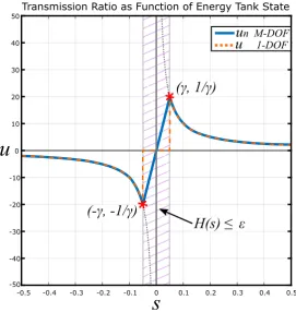
4.4 Transmission ratiouplotted as a function ofs. . . 26
4.5 Layered scheme of the proposed controller. . . 27
5.1 KUKA LWR 4+ manipulator schematic. . . 30
5.2 Bond graph model of a rigid body. . . 31
5.3 Manipulator’s link as a rigid body with reference frames. . . 32
5.4 Manipulator’s link bond graph representation. . . 32
5.5 Joint Bond-Graph Model. . . 33
5.6 Component-based model of the KUKA LWR 4+ manipulator. . . 34
6.1 Simulation - Energy and power limitation. . . 35
6.2 Simulation - Energy and power limitation, periodic motion. . . 36
6.3 Simulation - Energy and power limitation, periodic motion with collision. . . 36
6.4 Simulation - Reference tracking with collision. . . 37
6.5 Simulation - Energy tank and joint power. . . 37
6.6 Simulation - Performance and safety trade-off. . . 38
6.7 Simulation - Performance and safety trade-off. . . 38
6.8 Simulation - Depleted energy tank. . . 39
6.9 Simulation -u1=0 whenH1(s1)≤²multi-DOF. . . 40
6.10 Simulation -u1=(−τc1/γ 2)s 1whenH1(s1)≤²multi-DOF. . . 40
6.11 Simulation - Manipulator out of control. . . 41
6.12 Simulation - Joint E1(J3) out of control. . . 41
6.13 Simulation - Joint E1(J3) virtually shut down. . . 42
6.14 Simulation - Energy tank in joint E1(J3) initially loaded with a higher value. . . . 42
6.15 Experimental set-up. . . 43
6.16 Overview of the FRI control system architecture. . . 43
xii Development of a SAIP Controller for a Multi-DOF Manipulator
A.1 Standard feedback control system. . . 49
A.2 Block diagram representation of damping injection framework. . . 50
A.3 Bode diagram of a nominalP Dcontroller. . . 50
A.4 Nonlinear effects on manipulator masked with a diagonal inertiaIm. . . 51
B.1 20-simcontrolled system. . . 53
B.2 20-simjoint angles set-points submodel. . . 53
B.3 20-simcontroller submodel. . . 54
B.4 20-simcomponent based model of the manipulator. . . 54
List of Tables
4.1 Effort and flow power conjugated variables for different physical domains. . . 214.2 Energy tank concept comparison between 1-DOF and multi-DOF systems. . . 25
5.1 Axis data of the KUKA LWR manipulator. . . 30
6.1 Experimental results - Safe human robot interaction. . . 44
xiii
List of Acronyms
DOF Degree of Freedom
DLR German Aerospace Center
EJS Eulerian Junction Structure
FRI Fast Research Interface
HIC Head Injury Criteria
HIP Head Impact Power
HRI Human-Robot Interaction
KRC KUKA Robot Controller
KRL KUKA Robot Language
LWR Lightweight Robot
PBC Passivity-Based Control
PCH Port-Controlled Hamiltonian
PD Proportional-Derivative
pHRI Physical Human-Robot Interaction
PID Proportional-Integral-Derivative
POE Product of Exponentials
RAM Robotics and Mechatronics
ROS Robot Operating System
SAIP Safety-Aware Intrinsically Passive
SE Special Euclidean Group
SO Special Orthogonal Group
1
1
Introduction
1.1 Context
Recent advances in the robotics field have accelerated the development of robots that can op-erate close to humans. To empathize this feature, these new type of robots are often called
Cobots, from the neologism of the words collaborative and robot [8].
Since these robots are expected to share their workspace with a human operator, physical con-tact may occur for two reasons mainly: accidentally, in case of collisions; or deliberately, if the human operator is supposed to physically interact with the robot during work. In both cases, it is important to guarantee a safe physical interaction for injury prevention [62, 8].
Collaborative robots are expected to operate in unstructured human environments and inter-act with unknown objects [3]. Thus, controller design should incorporate safety issues such as: introducing compliance to minimize injury in case of uncontrolled impact, ensuring asymp-totic stability even during interaction and provide limitations in terms of velocities or forces exerted by the robot [8, 54].
A compliant behavior for a robotic manipulator can be obtained at the control level by using techniques such as the impedance control [28]. In this way, the joint torques can be reduced in case of an impact, protecting the robot itself and the individual. To achieve implicit safety, robotic arms in a domestic environment are designed to be lightweight and compliant [27, 3, 10, 31], such that any possible injury is prevented in case of an uncontrolled collision with a human.
1.2 Research Proposal
One of the research topics of the Robotics and Mechatronics (RAM) laboratory at the University of Twente, is to design personal robots that operate safely in home environments by using stan-dardized architectures. Recently, a novel intrinsically passive control design was proposed that is suitable for human-friendly robotic manipulators because of the compliance and passivity it introduces into the system. Nevertheless, this novel algorithm was only tested with a 1-Degree of Freedom (DOF) actuator, and needs to be extended to a multi-DOF instance and evaluated experimentally.
The passivity concept will be adapted to a multi-DOF manipulator, and enhanced by including energy and power based safety norms in a Cartesian impedance controller design, ensuring safe interaction in a domestic environment. In this direction, the main research objective is:
2 Development of a SAIP Controller for a Multi-DOF Manipulator
1.3 Related Work
Concerning stability, different authors have exploited passivity theories to design controllers which ensure asymptotically stability of a robotic manipulator [37, 4, 65]. By definition, passive systems are stable dynamic systems whose total energy is less than or equal to the sum of its initial energy and any external energy supplied to it by interaction [38, 6]. As proven in [51], if the robot is not strictly passive, it is always possible that a passive environment destabilizes the robot’s motion and extracts infinite energy from it.
Because most tasks can be defined in terms of energy, different authors introduced energy tank methods [39, 19], to preserve passivity. By doing so, the robot can use a certain amount of energy to perform a task but no more than that.
While addressing the issue of human friendly robots, different safety criteria can be defined based on risk assessments and performance requirements [62, 8]. In [7], the Head Injury Crite-ria (HIC) is used as a safety criteCrite-ria to identify a performance limit given in terms of maximum allowed link velocity. Hence, one of the control objectives is to guarantee that the desired tra-jectories satisfy a safety velocity limitation. The trade-off between safety and performance is evaluated for different actuation mechanisms and possible controller schemes [66].
In [26], the maximum impact force that can be exerted by a multi-DOF robot is used to define a force based safety metric called impact potential. This metric is used to define a hierarchical controller composed by a low level motion controller and a high level safety protection layer. The motion controller generates required torque outputs to achieve a desired motion trajectory and the safety layer checks the impact potential that will be achieved due to the motion con-troller torque. If the impact potential is within the safe limit it is passed to the robot’s actuators and if not the torque is cut to an appropriate value to avoid unsafe collisions.
Regarding energy limitations as safety measures, [33] uses energy based metrics to design an energy regulation controller that limits the total energy of a manipulator within the required safety limit by modulating the desired trajectory reference. A power based safety metric is pro-posed in [36], where the minimum power that can cause a concussion from an impact on a hu-man head is investigated, defining a power limit metric experimentally. Energy related safety indicators are proposed in [34], where the kinetic and potential energies of the system are used as constraints to establish a safe environment around a manipulator’s workspace.
The work done in [55], introduces an impedance controller with safety limitations which is defined through a risk based safety analysis performed, following the guideline defined in [25]. In particular, power and total energy of the system are considered as safety metrics for this analysis. The result is a variable impedance controller for a 1-DOF actuator which guarantees safety, through energy and power limitation and establishes passivity and energy consistency of the system, by decoupling the controller from the robot with an energy-tank [48, 39].
Similarly to [33] and [34], and considering the results presented in [36], a safety-aware impedance controller is developed in this thesis. This controller limits the energy exerted by the robot, and the power flowing from the controller to the manipulator, such that safe Human-Robot Interaction (HRI) is guaranteed.
In particular, the control scheme begins with a basic impedance controller which can be tuned according to certain performance requirements [32, 53], and then modifies the controller pa-rameters (i.e. stiffness and damping) such that safety limits defined in a combined energy and power based metrics are met. This variable impedance controller is connected to an energy tanks system to guarantee the passivity and energy consistency of the system.
CHAPTER 1. INTRODUCTION 3
1.4 Report Outline
The rest of this thesis report is organized as follows:
• Chapter 2is introduced as background material for the mathematics notation employed within the context of the project. Relevant equations used for modelling are presented using screw theory notation.
• Chapter 3focuses on the principle behind impedance control. This concept is presented for a 1-DOF case, and then extended to a multi-DOF. The resulting Cartesian impedance controller is then shaped using energy and power based safety metrics to come up with a safety-aware controller.
• Chapter 4 introduces port-Hamiltonian systems as the fundamental starting point of passive controllers. An energy-tank based approach is presented for a 1-DOF case, and the extended for a multi-DOF general case. The main contribution of this project is pre-sented at the end of this chapter, in a multi-layered structure control scheme.
• Chapter 5briefly describes the multi-DOF platform employed for simulations and ex-periments. A port-based modelling of this manipulator is described, and presented as a standardized architecture for reusability and/or extendability.
• Chapter 6displays the evaluation of the controller proposed in Chapter 4. Simulation and experimental results are presented here.
• Chapter 7summarizes the main contributions of this project. The results from the ex-periments presented in Chapter 6 are discussed, and an overview of the future work and recommendations is provided.
5
2
Mathematics of Robotic Manipulators
This chapter is included as background material to grasp the terminology and main mathe-matical concepts in robotics, used within the context of this project. The adopted notation to mathematically express the kinematics and dynamics of the analyzed manipulator is screw theory, which was early developed in [5] and later employed by different authors in the field of robotics [35, 50, 46, 45].
2.1 Kinematics of Serial Manipulators
Any point in a coordinate frameΨi, can be expressed relatively to a frameΨj, in vector form
as follows:
pj=Rijpi+pij (2.1)
which can be rewritten in matrix form as:
Ã
pj
1
!
| {z }
Pj
=
Ã
Rij pij
0>
3 1
!
| {z }
Hij
Ã
pi
1
!
| {z }
Pi
(2.2)
The matrixHij∈R4×4, is known as thehomogeneous transformation matrix, used to transform vectors from a coordinate framei, to a coordinate framej, and belongs to the Special Euclidean Group (SE)(3):
SE(3) :=
(Ã
R p
0>3 1
!
: R ∈SO(3),p ∈ R3
)
(2.3)
wherep andR, are the position and orientation of a rigid body, respectively. The rotation matrixR, is a square orthogonal matrix that belongs to the Special Orthogonal Group (SO)(3):
SO(3)=©R ∈ R3 : RR>=I, detR= +1ª
(2.4)
The position and orientation of a point with respect to any coordinate frame, can be expressed as products of transformation matrices, following the so-called chain rule:
Hn0=H10H21H32· · ·Hnn−1 (2.5)
According to Chasles’ Theorem, any rigid body motion can be accomplished by means of a rotation about a unique geometrical line in space, followed by a translation along that line. This line is called screw axis [5, 61]. In screw theory, generalized velocities for rigid bodies are described by means of atwist[35, 52]. A twist can be expressed in vector and matrix form as:
T = µω υ ¶ ˜ T=
µω υ˜
0 0
6 Development of a SAIP Controller for a Multi-DOF Manipulator
whereωandυ, stand for the rotational and translational velocities respectively, of thex, y, andzaxes. Note that the tilde mark inω˜, is known as the tilde operator, which associates in a unique way a vector with its matrix form as follows:
ω= ωx ωy ωz
ω˜ =
0 −ωz ωy
ωz 0 −ωx
−ωy ωx 0
(2.7)
The matrix in (2.7) is a skew-symmetric matrix, which belongs to the vector spaceso(3):
so(3)=©ω˜ ∈ R3 : ˜ω>= −ω˜ª
(2.8)
Analogous to points in a Cartesian space, change of coordinates can also be achieved on twists by pre- and post-multiplying ˜T with an homogeneous matrix:
˜
Tkj,l =HijT˜ki,lHij (2.9)
Nevertheless, in most cases, it is easier to work with the six-dimensional vector form of a twist. Thus, the change of coordinates for twists in vector form is given by:
Tkj,l=AdHj i
Tki,l where AdHj i =
Ã
Rij 0
˜
pijRij Rij
!
(2.10)
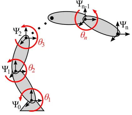
With this in mind, given the joint angles it is easy to find the end-effector position and orienta-tion of serial kinematic chains, as in Figure 2.1.
Ψ
0Ψ
1Ψ
2Ψ
n-1Ψ
nθ
1θ
2 [image:22.595.181.392.399.582.2]θ
3θ
nFigure 2.1:Serial kinematic chain.
2.1.1 Brockett’s Product of Exponentials Formula for Direct Kinematics
Considering that:
˜
Tij,j=H˙ijHij ⇒ H˙ij=T˜ij,jHij
IfT˜ij,jis constant, the solution to the previous differential equation is given by:
Hij(qj)=exp
µ ˜ b
Tij,jqj
Hij(0) (2.11)
whereHij(0) is the position forqi =0. In view that the homogeneous transformation matrix
goes along with the chain rule:
Hn0=H10H21H32· · ·Hnn−1 (2.12)
CHAPTER 2. MATHEMATICS OF ROBOTIC MANIPULATORS 7
the expression in (2.11) can then be substituted in (2.12) to get:
Hn0¡
q1,q2,q3,· · ·,qn¢=e
µ
˜
b T0,01 q1
H10(0)
| {z }
H0 1(q1)
e
µ
˜
b T1,12 q2
H21(0)
| {z }
H1 2(q2)
e
µ
˜
b T2,23 q3
H32(0)
| {z }
H2 3(q3)
· · ·e
µ
˜
b
T(nn−1),(n−1)qn
Hn(n−1)(0)
| {z }
Hn(n−1)(qn)
Subsequently, by using the identity property, and change of coordinates of the exponential ar-gument:
Hn0¡
q1,q2,q3,· · ·,qn¢=
I I
z }| { z }| {
e
µ
˜
b T0,01 q1
H10(0)e
µ
˜
b T1,12 q2
H01(0)H10(0)H21(0)e
µ
˜
b T2,23 q3
H32(0)H03(0)H30(0)· · ·
| {z } | {z }
e
µ ˜ b
T0,12 q2
e
µ ˜ b
T0,23 q3
·
| {z }
e
µ ˜ b
T0,(nn−1)qn
¶ · ·e
µ
˜
b
T(nn−1),(n−1)qn
Hn(n−1)(0)
I
z }| {
H0n(0)Hn0(0)
Simplifying, the forward kinematics map for an arbitrary open-chain manipulator withn de-grees of freedom can be expressed as:
Hn0
¡
q1,q2,q3,· · ·,qn¢=e
µ
˜
b T0,01 q1
e
µ
˜
b T0,12 q2
e
µ
˜
b T0,23 q3
· · ·e
µ
˜
b T0,(nn−1)qn
Hn0(0) (2.13)
Equation (2.13) is known asBrockett’s Product of Exponentials(POE) formula [16], and its use becomes very advantageous since it only depends on the joint anglesqi. Note that the twists
in this expression, are unit twists of the form:
b
T=
µ b ω
r×ωb 
Furthermore, each exponential product in (2.13) can be determined with the Rodrigues’ for-mula [35]:
eωbθ=I+
b
ωsinθ+ωb
2(1
−cosθ) (2.14)
The theory behind Brockett’s POE can be found in [16]. For a well explained procedure, and details behind the intermediate expressions, refer to [35] and [52].
2.1.2 Spatial Manipulator Jacobian
The complete direct kinematics of a manipulator is described by the end-effector position and velocity. It can be proved that given a serial chain manipulator as in Figure 2.1, the end-effector twist can be determined by the following expression:
Tn0,0=T10,0+T20,1+T30,2+ · · · +Tn0,(n−1) (2.15)
From the definition of kinematic pair [52], the relative motion between two objects for a one degree of freedom joint is constrained by a twist of the form:
Tn(n−1),(n−1)=Tb
(n−1),(n−1)
n ·q˙n (2.16)
whereq˙nis the joint velocity, and for a rotational jointTb
(n−1),(n−1)
n is a constant unit twist of the
form:
b
Tij,j=
µ b ω
8 Development of a SAIP Controller for a Multi-DOF Manipulator
for anyr connecting the origin of the reference frame to the joint axis [52]. Substituting (2.10) and (2.16) in (2.15), and rearranging yields:
Tn0,0=
³ b
T10,0 AdH0 1Tb
1,1 2 AdH0
2Tb
2,2
3 · · · AdH0
n−1Tb
(n−1),(n−1)
n
´
| {z }
J(q)
·£q˙1 q˙2 q˙3 · · · q˙n¤>
| {z }
˙
q
Tn0,0=J(q)q˙ (2.17)
whereq˙∈Rn is the joint velocity vector; and the matrixJ(q)∈R6×n, is known as the manip-ulator Jacobian, which maps the instantaneous velocities of each joint with the instantaneous end-effector’s twist, with respect to the base [18, 46, 61].
2.2 Dynamics of Serial Manipulators
The whole screw theory was developed embracing Chasles’ and Poinsot’s theorems, published in [5]. Poinsot discovered that any system of forces acting on a rigid body, can be expressed as a single force acting along a line, plus a torque around the same line [5, 35]. This force is known aswrench, and is the dual of a twist. Accordingly, wrenches can also be expressed in vector and matrix form as:
W =¡m f¢ ˜
W=
µ˜
f m>
0 0
(2.18)
Note that the vector form of a wrench, is a six-dimensional row vector since:
Power=F v ⇒ Power=W T (2.19)
Hence, the change of coordinates for wrenches in vector form is given by:
(Wi)>=Ad> Hij(W
j)> where Ad> Hij=
Ã
Rij −Rijp˜ij
0 Rij
!
(2.20)
2.2.1 Newton-Euler Equation of Motion for a Rigid Body
Considering the principal inertia frameΨk, located in the center of mass of a rigid body, and
properly oriented which produces an inertia tensor in its simplest form as:
I=
µJ
0
0 mI
(2.21)
whereJis a diagonal matrix, the dynamic equations of a rigid body can be expressed by means of screw theory defining a momentum screw [47]:
(P)>
| {z }
p = I |{z} m T |{z} υ (2.22)
Thus, Newton’s law is generalized for rigid bodies as:
˙
P0=W0 (2.23)
where ˙P0 is the rate of change of momentum with respect to time, known as moment; and W0is the wrench acting on the rigid body, expressed in the inertial frameΨ0. If the motion is expressed in the body’s coordinate frameΨk, (2.23) becomes:
( ˙Pk)>=ad> Tkk,0(P
k)>+(Wk)> (2.24)
CHAPTER 2. MATHEMATICS OF ROBOTIC MANIPULATORS 9
where:
ad> Tkk,0=
à ˜ ωk,0
k 0
˜ υk,0
k ω˜
k,0
k
!
(2.25)
Equation (2.24) describes the dynamics of a rigid body expressed in the principal inertia frame Ψk, and is equivalent to:
IkT˙k,0
k =
Ã
−ω˜kk,0 −υ˜kk,0
0 −ω˜kk,0 !
IkTkk,0+(Wk)> (2.26)
⇓
Ã
Jω˙kk,0
mIυ˙kk,0 !
+
à ωk,0
k × Jω
k,0
k
ωk,0
k × mIυ
k,0
k
!
=
Ã
(τk)>
(fk)>
!>
(2.27)
Equation (2.27) is known as theNewton-Euler equation, which is expressed in the body’s prin-cipal inertia frame, and describes the motion of a rigid body subject to an external wrench [47, 50]. The relevance of this equation becomes evident in Section 5.2.1, where it is used to model the manipulator’s links to carry out simulation experiments.
2.2.2 General Dynamics Equation
A robotic manipulator withndegrees of freedom is distinguished by a set ofngeneralized co-ordinatesq>=[q1 q2 · · · qn] which define the so-calledjoint space. These coordinates are
defined for serial manipulators with revolute joints, by the angle between two consecutive el-ements of the kinematic chain [18]. Thus, the general dynamics equation of a generic robotic manipulator can be written in joint space as:
τ>=M(q)q¨+C(q,q˙)q˙+G(q) (2.28)
whereM(q)∈Rn×n is the configuration dependent inertia matrix;C(q,q˙) represents all ve-locity dependent inertia forces such as Coriolis, centripetal, and gyroscopic effects;G(q) rep-resents the gravitational forces; andτ>is the equivalent joint torques due to all external and interaction forces [45, 46].
11
3
Impedance Control of Robotic
Manipulators
Industrial robots commonly use position, or force control when it comes to executing planned motion tasks in a known environment. Nevertheless, control of a vector quantity (e.g. force, velocity, or position) alone is not sufficient [29]. With pure position control, if there is contact with an object, the robot is not expected to go through it. Equivalently, with pure force control tasks and motions without contact become difficult to implement [60].
An alternative control technique is an interaction control scheme, where the manipulator is no longer treated as an isolated system. Thus, the dynamic behavior of the manipulator is regulated as it is interacting with the environment [50]. The manipulation is done through energy exchange, in a bidirectional signal exchange between robot and environment during interaction, where these signals are power conjugated variables. In this way, the interaction with the environment can be controlled by adjusting the dynamics of the robot [42].
One of the most consistently used interaction control schemes is impedance control [28, 29, 30]. This notion is introduced as the groundwork for a proposed novel Cartesian impedance controller in this chapter. The featured controller allows safe HRI through energy and power limitations. The concept behind this controller is first presented for a 1-DOF case, and then extended to a multi-DOF instance. Subsequently, feedforward control is presented as an ex-tension to this, or any other Cartesian impedance controller, in pursuance of performance en-hancement tool.
3.1 Impedance Control
The underlying distinctness between impedance control and traditional approaches is that al-ternatively to controlling a state variable alone, such as position, velocity, or force, a dynamic relationship is established between them [40]. This control strategy offers desirable attributes, such as direct specification of the mechanical interaction with the environment. This interac-tion is distinguished by the energy exchange, in a bidirecinterac-tional way, between manipulator and environment [50].
12 Development of a SAIP Controller for a Multi-DOF Manipulator
3.1.1 Damping Injection Framework
Consider a simplified robotic manipulator modeled as a 1-DOF equivalent massm. Ifmhas to be moved to a desired positionxd, the most elementary controller that can achieve this task is a
spring connected between the mass andxd. In order to avoid continuous oscillation of the
sys-tem, a damper is added as shown in Figure 3.1. The resulting controller is a simple impedance controller, which is equivalent to a traditional Proportional-Derivative (PD) controller, that can shape the dynamic behavior of the system.
Plant Controller
kc x
xd
b
Fext
Figure 3.1:Elementary Impedance Controller.
The dynamic equation of the dynamic system in Figure 3.1 is given by:
Fext−kc(xd−x)−bx˙=mx¨ (3.1)
This expression clearly shows the need to measure the positionx, and velocity ˙x. Nevertheless, the latter is roughly never available. Thus, the damping injection framework is proposed as an alternative way to consistently create artificial damping [49]. This notion resolves the need of velocity measurement, and circumvents the existing drawbacks in other velocity estimation solutions such as numerical differentiation, state variable filters, or state observers [49, 53].
The damping injection framework is introduced as an extension of the basic impedance con-troller from Figure 3.1, introducing a virtual massmc, and a spring that connects this mass with
the simplified plant. See Figure 3.2.
Plant Controller
kc xd
b
Fext
mc
x
m k
[image:28.595.204.368.188.276.2]xc
Figure 3.2:Damping Injection Concept.
The dynamic equations of the extended system, shown Figure 3.2, are given by:
mx¨+Fext−k(xc−x)=0
mcx¨c−k(x−xc)+bx˙c−kc(xd−xc)=0
(3.2)
Then, if a very stiff virtual springkand a small virtual massmcare chosen, the massm, which
represents the simplified robot plant, will adopt the same motion as the virtual massmc.
Sub-sequently, a damper can be applied on the virtual mass to insert damping in the plant motion. In this way, the mass velocity is known from the state of the controller. This implementation only requires measurement of the plant position, and ensures a strictly passive behavior with closed loop stability [49, 53].
CHAPTER 3. IMPEDANCE CONTROL OF ROBOTIC MANIPULATORS 13
3.1.2 Multidimensional Instance
The multidimensional case is based on the same reasoning. Considering the Lagrangian dy-namic equation of a general multi-DOF serial manipulator:
τ>=M(q)q¨+C(q,q˙)q˙+G(q) (3.3)
whereM(q)∈Rn×n is the configuration dependent inertia matrix;C(q,q˙) represents all ve-locity dependent inertia forces such as Coriolis, centripetal, and gyroscopic effects; andG(q) represents the gravitational forces [18]. Certainly, an equivalent physical controller must be designed in order to compensate for the mentioned terms. The analogous equivalence of the damping injection framework, from Figure 3.2, in Cartesian space is depicted in Figure 3.3.
q
1q
2q
3q
4q
5b
5b
4b
3b
2b
1H
dH
K
[image:29.595.177.427.231.498.2]B
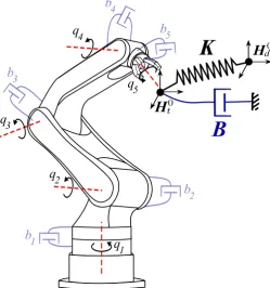
Figure 3.3: Impedance control of a multi-DOF manipulator in Cartesian space. A multidimensional virtual spring with stiffness matrixK∈R6×6is connected between the current and desired end-effector’s configuration, defined byHt0andHd0respectively. Damping can be either introduced through a spatial damper with damping matrixB∈R6×6, or in joint space via a damperbnon each DOF.
The Cartesian impedance controller is composed of a spatial geometric spring with a symmet-ric stiffness matrixK∈R6×6, virtually connected between the current and desired end-effector’s configuration; damping can be either added via a multidimensional damper with damping ma-trixB∈R6×6, or in joint space via a damperbnon each DOF, as indicated in Figure 3.3. Matrices
Ht0andHd0are homogeneous matrices, as defined in (2.3), which describe the current and de-sired configurations of the end-effector, respectively.
The spatial geometric spring produces a wrench acting on the manipulator’s end-effector, which is defined as [50, 60]:
Ã
(mtk)>
(fkt)>
!>
| {z }
(Wt k)>
=
Ã
Ko Kc
Kc> Kt
!
| {z }
K
Ã
δθd t
δpdt
!
| {z }
δχ
(3.4)
whereδχ=[(δθdt)> (δpdt)>]>is an infinitesimal twist displacement in vector form, andKt,
respec-14 Development of a SAIP Controller for a Multi-DOF Manipulator
tively1. If a set of co-stiffness matricesGt,Go, andGcare defined as:
Gx=
1
2tr (Kx)I−Kx for x=t,o,c (3.5)
where tr(), is the tensor trace operator, the expression in (3.4) can be rewritten as:
¡ ˜
mkt¢
= −2as³GoRtd
´
−as³GtRdt p˜dt p˜tdRdt
´
−2as³Gc p˜dt Rtd
´
¡˜
fkt¢
= −Rdt as³Gt p˜dt
´
Rtd−as³Gt Rdt p˜dt Rtd
´
−2as³GcRtd
´ (3.6)
where the operator as() gives the antisymmetric part of a square matrix; Rdt andpdt are the rotation matrix and position vector, respectively, of the relative configuration betweenHt0and
Hd0, which is defined as:
Htd= Ht0·
¡
Hd0¢−1
=
Ã
Rtd pdt
0>3 1
!
(3.7)
For a detailed procedure on how to rewrite (3.4), into its equivalent form in (3.6), refer to [50]. In case damping is injected in Cartesian space instead of joint space, the wrenchWdtacting on the end-effector due to this damper can be similarly determined as presented in [22]. Thus, the combined wrench acting on the end-effector, expressed in the end-effector’s configuration, is given as:
Wt=Wkt+Wdt (3.8)
Having the total virtual wrench applied on the end-effector, it is possible to calculate the joint torques required to emulate this equivalent wrench. Due to the duality nature of force and ve-locity, the Jacobian expression from (2.17) can be used to compute the equivalent joint torques as [52]:
τ>=J>(q) (W0)> where (W0)>=Ad> Ht
0
(Wt)> (3.9)
The latter expression can be further extended to define a control law as:
τ>=J>(q)(W0)>+
b
C(q,q˙)q˙ +Gb(q) (3.10)
whereCb(q,q˙)q˙ is the compensation term for Coriolis and centrifugal forces, andGb(q)
com-pensates for gravity.
One of the advantages of using a Cartesian impedance controller resides in its clear and simple physical interpretation, as depicted in Figure 3.3. This design choice allows a simple analysis of the controller’s energy and power, exchanged with the manipulator [50]. This impedance control scheme can be employed as base groundwork for the implementation of different con-trollers that fulfill certain specifications in terms of performance [32, 53] (See Appendix A), or other requirements. In the context of this prokect, a safety-aware impedance controller is pro-posed in the following sections.
3.2 Safety-Aware Robot Control
Recent evolution in the field of robotics have allowed the development of robots that can op-erate close to humans. Thus, new robots designs must consider coexistence and cooperation with humans in different applications such as assisted industrial manipulation, collaborative assembly, domestic work, entertainment, rehabilitation, or medical applications [8, 25]. In this context, safety becomes a topic of supreme importance and hazardous circumstances must be
1Note that the rotational and translational components of the elastic wrench have been transposed, since a
wrench was defined as a row vector in (2.18), so that (2.19) is satisfied.
CHAPTER 3. IMPEDANCE CONTROL OF ROBOTIC MANIPULATORS 15
considered. Nevertheless, supervision of risk for humans sharing workspace with robots in-volves very broad considerations in general, varying from potential electrical hazard, damaged pressurized fluid hose, pinching of limbs, dropping parts, etc.
This means that one of the most challenging features for the new generation of robots will be Physical Human-Robot Interaction (pHRI) [8], where humans and robots share the same workspace in an interaction environment. Robots in a human-friendly environment may phys-ically interact with a human for two main reasons: accidentally, in case of unexpected colli-sions; or deliberately, if the human operator is supposed to physically interact with the robot during work. In both cases, it is important to guarantee a safe physical interaction for injury prevention [3, 62].
A power based safety metric called Head Impact Power (HIP) is proposed in [36]. In this work, the probability of concussion from an impact on a human head is investigated. The results of the presented experiments identify the minimum power that can cause injury to a person. The power limits are then defined as:
Plimit= (
12K W Frontal Impacts
10K W Non-Frontal Impacts (3.11)
The works presented in [63] and [64], identify the maximum allowed energy that can cause neck fracture and failure to cranial bones, respectively. Thus, the energy limits defined for this types of injuries are:
Elimit=
517J Adult cranium bone failure 127J Infant cranium bone failure
35J Neck fracture
(3.12)
One of the most widely used safety norms regarding robotic safety is the HIC, which was first proposed within the automotive industry by Versace in [59]. This metric, along with the previ-ously mentioned, have constituted a useful foundation for the development and evaluation of safety based robot controllers [26, 66, 7, 55].
In conjunction with power limitation as safety metric [36] and limitation of the manipulator’s total energy similarly to [33], a safety-aware impedance controller is defined in Cartesian space. This controller limits the energy exerted by the robot and the power flowing from the controller to the manipulator, such that safe HRI is guaranteed.
Particularly, the proposed controller begins with a basic impedance controller which can be tuned according to certain performance requirements [32, 53], and then modifies the controller parameters (i.e. stiffness and damping) so that established safety limits are met.
A 1-DOF safety-aware impedance controller, which combines energy and power based safety metrics, was first developed by Tadele and presented in [55]. The core ideas behind the pro-posed controller are summarized and disclosed in the following section, and then used to ex-tend this notion to a multi-DOF instance.
3.2.1 Safety-Aware Impedance Control for a 1-DOF General Case
The interaction scheme proposed by impedance control design provides a favorable tool for human friendly robots, as it enhances safety by introducing compliance and guarantees sta-bility due to its passive essence [38]. Its clear and simple physical interpretation, allows the analysis of its energy content and exchanged power with the manipulator.
Considering the dynamic system from Figure 3.2, if a very stiff binding spring is chosen such thatk>>kc, and a very small virtual mass is defined asmc <<m, the dynamics of the
16 Development of a SAIP Controller for a Multi-DOF Manipulator
elemental impedance controller can be written as:
Fc=k(xd−x)−bx˙ (3.13)
The parameters of this control law can be designed by choosing metrics which establish safe pHRI [62, 25]. Consider the total energy of the system in Figure 3.1, which is defined by the sum of the kinetic energy of the plant, and the potential energy of the spring:
Etot=
1 2kx
2
e+
1 2mx˙
2 (3.14)
wherexe=xd−xis the position error, and ˙xis the velocity of the simplified plant, represented
by a single mass. If an energy threshold is defined, based on the amount of energy that a human can tolerate without sustaining injury [63, 64], the parameterkcan be determined in such a way that the total energy of the system does not exceed the maximum allowed valueEmax. In this
way, the stiffness parameter is dynamically modified as:
k=
k0, Etot≤Emax
2Emax−mx˙2
(xd−x)2
, Etot>Emax
(3.15)
wheremis the simplified plant mass, andkois the controller stiffness initially chosen based on
performance requirements [53, 58]. In this way, parameterkin (3.13) will be scaled according to (3.15), if the total energy of the system exceedsEmax due to an uncontrolled situation or
accidental collision.
In addition to the energy limitation as a safety metric, a power based metric can also be en-abled. On account that a manipulator is driven by controlled actuators, the amount of power transfered to a human during an uncontrolled collision can be limited similarly. Considering the impedance control law (3.13), the power that flows from the controller to the manipulator is given by:
Pc
|{z}
P
= (k(xd−x)−bx˙)
| {z }
F ˙ x |{z} v (3.16)
In this way, after a stiffness valuek is determined as in (3.15), the power flow between con-troller and plant can be similarly limited to a maximum valuePcmax. The latter is attained by computing the damping parameterbas follows:
b=
b0, Pc≤Pmax
k(xd−x) ˙x−Pmax
˙
x2 , Pc>Pmax
(3.17)
wherek is the stiffness parameter computed with (3.15), andb0 is an initial damping value determined with performance specifications [53]. The result is an impedance controller, with variable stiffness and damping parameters, that adheres to established safety metrics.
3.2.2 Safety-Aware Cartesian Impedance Control for a Multi-DOF General Case
Considering the configuration of Figure 3.3, extension of the safety-aware controller to a multi-DOF instance is effected by employing the impedance control law from (3.10), whereas for this case damping is injected in joint space for each DOF:
τ>=J>(q)(W0
k)>−B¯q˙ +Cb(q,q˙)q˙ +Gb(q) (3.18)
where (Wk0)>is the wrench acting on the end-effector produced by the multidimensional spa-tial spring, expressed in the inerspa-tial reference frame;Cb(q,q˙) andGb(q), are the Coriolis and
CHAPTER 3. IMPEDANCE CONTROL OF ROBOTIC MANIPULATORS 17
gravity compensation respectively; and ¯B ∈Rn×n=diag([b1· · ·bn]) is a diagonal matrix with
damping parameters for each joint.
The adoption of the safety-awareness concept to Cartesian space requires the evaluation of the total energy of the system, and power transferred from controller to manipulator. The total energy of the system is the sum of the kinetic energy of the manipulator, and the potential energy due to the spatial spring. In this direction, the kinetic energyTK of the manipulator is
defined as:
TK(q,q˙)=
1 2q˙
>M(q)q˙ (3.19)
whereM(q) is the inertia matrix, andq˙is the joint velocity vector. Furthermore, the potential energyVPstored in the spatial spring, acting on the end-effector, is given by:
VP(R
d
t,pdt) = Vt(Rtd,pdt) +Vo(Rtd)+Vc(Rtd,pdt) (3.20)
whereVt,Vo, andVc, are the translational, rotational, and coupling components, respectively,
of the total potential energy of the multidimensional spring. These components are defined in terms ofpdt andRdt, which define the position and orientation of the relative configuration (3.7). The elements of (3.20) are computed as defined in [21, 50]:
Vt(Rdt,pdt)= −
1 4tr
³ ˜
ptdGt p˜dt
´
−1
4tr
³ ˜
pdt Rdt GtRdt p˜td
´
Vo(Rtd)= −tr
³
GoRtd
´
Vc(Rtd,pdt)=tr
³
GcRdt p˜dt
´
(3.21)
where tr() is the tensor trace operator, andGt,Go, andGcare the translational, rotational, and
coupling co-stiffness matrices respectively, defined in (3.5).
Equivalently to the 1-DOF case, energy limitation is established by regulating the amount of po-tential energy that the spatial spring supplies to the system. As it can be observed, the popo-tential energy components in (3.21) are all proportional to the co-stiffness matricesGx(forx=t,o,c).
Henceforward, by choosing an array of initial stiffness valuesKx (forx=t,o,c), a set of initial
co-stiffness matricesGxi can be computed with (3.5), defining in this way the energy content of the system as:
Etoti = TK(q,q˙) +VPi(R
d
t,pdt) (3.22)
whereVPi is the potential energy of the controller spring due to the initial co-stiffness matrices
Gxi. Consequently, the total energy of the system can be regulated by scaling the initial co-stiffness matrices with a factorλ:
Gx=λ·Gxi for x=t,o,c (3.23)
By establishing a threshold valueEmax, defined based on safety regulations, the parameterλ
can be chosen as follows:
λ=
1, Etoti≤Emax
Emax−TK(q,q˙)
VPi(R
d t,pdt)
, otherwise (3.24)
whereEtoti, andVPi are the initial total and potential energies respectively, computed with the initial co-stiffness matricesGxi. Therefore, the total energy of the system can be expressed as:
Etot = TK(q,q˙) +λ·VPi(R
d
t,pdt) (3.25)
18 Development of a SAIP Controller for a Multi-DOF Manipulator
Analogously to the 1-DOF case, the power transferred from the controller to the plant during motion of the manipulator can be regulated by setting a power based safety metric. If an initial damping matrix ¯Biis chosen, the power transferred from the controller is given by:
Pci = ¡
J>(q)(Wk0)>−B¯iq˙
¢> ˙
q
| {z }
Pcm
+ Gb(q)q˙ | {z }
Pcg
(3.26)
where (Wk0)>is the wrench acting on the end-effector due to the spatial Cartesian spring,Pc
m is the power that flows from the impedance controller to the manipulator, andPcg is the power consumed for gravity compensation. In case of an uncontrolled collision with a human, the termPcmin (3.26) is the power that can be transferred to the individual, and the one which is to be limited below a tolerance value. The latter is attained by adjusting the initial damping with a scaling parameterβas:
¯
B=β·B¯i (3.27)
In this direction, establishing a threshold valuePmax, just as with the energy safety metric, the
scaling parameterβcan be chosen as:
β=
1, Pcm≤Pmax
¡
J>(q)(Wk0)>¢> ˙
q −Pmax
˙
q>B¯iq˙ , otherwise
(3.28)
Hence, the power expression can be rewritten as:
Pc = ¡J>(q)(Wk0)>− β·B¯iq˙¢>q˙ +Gb(q) (3.29)
3.3 Feedforward Control
Feedforward control is introduced as a method to track time varying trajectories and enhance disturbance rejection [46]. Given a Cartesian impedance controller, such as the one presented in Section 3.2.2 or Appendix A, feedforward control can be incorporated as an extension to en-hance the transient performance during reference tracking. The implementation of this con-troller is graphically depicted in Figure 3.4.
G(s) K(s) + -r(s) e(s) Q(s) + + y(s)
τ
FFτ
cτ
Figure 3.4:Standard feedforward control system.
For an n-link robot manipulator whose dynamics is described as in (2.28), the minimal-order inverse [43] of the manipulator model is chosen such that the feedforward controller is defined in the frequency domain as:
τFF=Q(s)·r(s)=
£
C+Bs+As2¤
·r(s) (3.30)
or in time domain as:
τFF=Cr(t)+Br˙(t)+Ar¨(t) (3.31)
CHAPTER 3. IMPEDANCE CONTROL OF ROBOTIC MANIPULATORS 19
whereA,B, andCare constant matrices defined as:
A=M(q) Bi j=∂
Ci(q,q˙)
∂q˙j
Ci j=∂
Gi(q)
∂qj
(3.32)
The control law (3.31) is realizable as long as the velocity and acceleration of the reference are available [44]. In this way, the output torque command sent to the manipulator is given by:
τ=τc+τFF (3.33)
21
4
Ascertaining Passivity Through Energy
Tanks
Passive systems are a class of dynamical systems in which energy exchange with the environ-ment plays a central role, since they cannot deliver more energy than what is stored [6]. The connection between the energetic features of a system and its stability, is delineated by means of Passivity-Based Control (PBC) [38].
A straightforward implementation of the safety-aware, and performance-based Cartesian trollers presented in Section 3.2.2 and Appendix A, respectively, contradicts the energetic con-sistency of impedance control design. The scaling of parameters in the controller allows inter-nal energy production, resulting in the loss of passivity of the overall system.
Thereupon, the energy-tank based controller implementation presented in [55] is adopted as a feasible way to circumvent this issue. After introducing general concepts of passivity and port-Hamiltonian systems, the energy-tank concept is first presented for a 1-DOF case, and then extended for a multi-DOF general case. The latter, together with the controller presented in Section 3.2.2, builds up the so-called Safety-Aware Intrinsically Passive (SAIP) controller, which is the major significance of this study.
4.1 Port-Hamiltonian Systems and Passivity
The essential starting point for PBC design is delineated by port-Hamiltonian systems, as they are a subclass of passive systems [42]. The port-Hamiltonian formulation, defines ports that build up interconnection with other systems. Power-conserving interconnection of port-Hamiltonian structures, allows consistent modeling of complex systems [37]. In this way, dif-ferent domain subsystems can be interconnected through power conjugated variables. See Table 4.1.
Table 4.1:Effort and flow power conjugated variables for different physical domains [42].
Domain Effort Flow
Mechanics (translational) ForceF Velocityv
Mechanics (rotational) Torqueτ Angular velocityω
Electric Voltageυ Currenti
Hydraulic Pressurep Volume FlowQ
22 Development of a SAIP Controller for a Multi-DOF Manipulator
A passive system satisfies the energy-balance equation [6]:
H[x(t)]−H[x(0)]
| {z }
stored energy =
Z t
0
u>(s)y(s)d s
| {z }
supplied
− d(t)
|{z}
dissipated
(4.1)
whereH(x) is the total (free) energy function, x∈Rn is the state vector, u and y are power conjugated variables, andd(t) is a positive dissipation function that describes (irreversible) energy conversion to the thermal domain.
The port-Hamiltonian formulation allows to describe a physical system in terms of energy ex-change. Energy-conserving physical systems can be explicitly modeled in the form of Port-Controlled Hamiltonian (PCH) as:
˙
x=J(x)∂H
∂x +g(x)u
y=g>(x)∂H
∂x
(4.2)
whereJis a skew symmetric matrix which establishes a power preserving interconnection be-tween internal variables, andg is a matrix defining how external power is distributed into the system [37]. The latter port-Hamiltonian formalism, provides a framework for modeling phys-ical systems that describe the energy storage and external interaction phenomena.
4.2 Energy-Tank Based Controller for a 1-DOF General Case
The nature of a physical system can be outlined in terms of energy flow and energy storage. In this direction, it is essential to define a function representing the total energy of the system. This function must have a Dirac structure [57], which is associated with a skew-symmetric ma-trix delineating the internal power preserving interconnections.
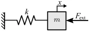
Consider the mass-spring system in Figure 4.1:
k
x
[image:38.595.210.360.473.529.2]F
extFigure 4.1:Elemental mass-spring system.
The total energy of the system is defined by the sum of the kinetic and potential energies as:
Etot=
1 2mx˙
2
+1
2kx
2 (4.3)
If (4.3) is rewritten as:
H(p,x)= p 2
2m+
1 2kx
2 (4.4)
the total energy expression can be displayed in the PCH form as:
d d t à x p ! = à 0 1
−1 0
! ∂H ∂x ∂H ∂p + Ã 1 0 !
Fext (4.5)
⇓
Ãx˙
˙ p ! = Ã 0 1
−1 0
! Ãkx
p m ! + Ã 1 0 !
Fext (4.6)
CHAPTER 4. ASCERTAINING PASSIVITY THROUGH ENERGY TANKS 23
Equation (4.6) is then used as the fundamental starting point of the energy-tank concept pre-sented by Tadele in [55]. The idea is to have a controlled system that satisfies the energy-balance equation (4.1). In this direction, due to its energy-storage nature, a spring is used to model an energy tank, such that a controller force output is applied to the system only when there is available stored energy. The physical interpretation of this notion is depicted in Fig-ure 4.2.
Plant
x
m
CU
Controller
x
du
H(s)
MT
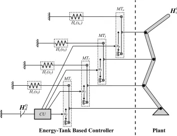
Figure 4.2:1-DOF energy-tank based controller.
The energy-tank concept of the simplified 1-DOF case incorporates a spring connected to a plant through a transmission. A computational unitCUis used to determine the variable trans-mission ratiou, such that the transmission elementM T, allows power flow from the controller to the plant as long as there is energy left in the tankH(s).
Henceforward, if a stiffness constant is chosen ask=1, andsis used to define the spring state ofH(s), the port-Hamiltonian formulation of the system in Figure 4.2 can be expressed as:
à s˙
Fout
!
=
Ã
0 u
−u 0
! Ãs
˙
x
!
(4.7)
In this way, the port-Hamiltonian expression in (4.7) can be used to set the desired transmission ratiouas:
u=−Fc
s (4.8)
whereFc is the controller force computed from (3.13). PBC design requires a physically
con-sistent energy coupling. Under these circumstances, the transmission ratiou should ensure isolation between plant and controller when the energy tank is depleted [55]. The latter is ac-complished by the following passivity assuring relation:
u=
−Fc
s , if (H(s) > ²) ∨(Pc<0))
0, otherwise
(4.9)
whereFc is the desired controller force; H(s)=12s2 is the potential energy in the tank model
designatingk =1;²is the minimum amount of energy allowed in the tank, before plant and controller isolation; andPcis the power flowing from the controller to the plant.