University of Warwick institutional repository: http://go.warwick.ac.uk/wrap
A Thesis Submitted for the Degree of PhD at the University of Warwick
http://go.warwick.ac.uk/wrap/1942
This thesis is made available online and is protected by original copyright. Please scroll down to view the document itself.
Using Pickering Stabilisation as a Tool for the
Fabrication of Supra-Colloidal Structures
Patrick James Colver MChem
PhD Thesis
University of Warwick
Chemistry Department
Table of Contents
Using Pickering Stabilisation as a Tool for the Fabrication of Supra-Colloidal
Structures...1
Table of Contents...2
Tables, Figures and Equations...4
Acknowledgements...9
Declaration...9
Summary...10
Abbreviations...11
Materials...13
Chapter 1: Introduction to Pickering Stabilisation...14
Chapter 2: Water-in-oil Pickering High Internal Phase Emulsions – Fabrication of Poly”colloido”(HIPE)s...30
Conclusion...47
Experimental...47
General conditions...47
Pickering Particle Formation...48
Inverse Pickering Emulsion Formation...49
Synthesis of di-tert-butylperoxyoxalate:...50
Chapter 3: Pickering Droplets – Control of Morphology...53
Conclusion...67
Methodology...67
Apparatus...67
Dispersion polymerisation...68
Chapter 4: Laponite Armoured Latex Particles Created Via Pickering Miniemulsion...71
Morphology of latexes made via Pickering miniemulsion polymerisation...77
Control of Particle Size in Pickering Miniemulsion Polymerisation...78
Rate of polymerisation in Pickering miniemulsion: polymerisation of styrene...89
Pickering miniemulsion polymerisation of various monomers...93
Conclusions...94
Methodology and raw data...95
Equipment:...95
Typical recipe for Pickering miniemulsion polymerisation:...95
Chapter 5: Development of Pickering Emulsion polymerisation...99
Laponite miniemulsion in the presence of charge surfactants:...103
Pickering Emulsion Polymerisation using Ludox-TM40 Silica Nanoparticles as Stabilizer...112
Conclusion...126
Methodology...126
Apparatus:...126
Typical Recipe for the preparation of multi-layered nanocomposite
latex particles using (I) as seed:...128
Raw Data...129
Chapter 6: Material Properties of Laponite Armoured Latex Particles...131
Heat resistance...132
Tacisity in Pressure Sensitive Adhesives...140
Conclusion...152
Methodology...152
Apparatus...152
Latex preparation...152
Probe-tack analysis of adhesive properties...153
DMA analysis...153
Chapter 7: Technical and Basic Theory...155
Polymerisation...155
Dynamic Light Scattering...160
Scanning Electron Microscope...161
Transmission Electron Microscope...162
Confocal Microscopy...162
Probe-tack...163
Dynamic Mechanical Thermal Analysis (DMTA)...165
Chapter 8...167
Final Words...167
Quotes:...167
Appendix...168
Tables, Figures and Equations
Chapter 1:
Equation 1-6
Figure 1: Graph showing the energy E, the calculated energy divided by Brownian motion kBT, at different displacements, z0, of the particle, where z=-1 is fully in the n-hexadecane phase and 1 is fully in the water phase
Equation 7
Figure 2: Diagram showing a particle at an interface and its contact angle.
Table 1:Scaffolding Strategies
Chapter 2:
Figure 1:Three possible designs using two different particles as Pickering stabilisers of
cellular polymer monoliths.2DProjections are from the side (y,z-plane). In example A the particles are randomly distributed over each water droplet, or cell; B shows a random blend of two Pickering emulsions with each droplet stabilised by only one type of particle; in C we pack one Pickering emulsion on top of the other creating distinct zones or layers, in the cellular monolith.
Equation 1
Figure 2: Collection of poly(n-butyl methacrylate) based cellular polymer monoliths produced via Pickering high internal phase emulsions after removal of reaction vial. The monoliths are placed upside down. The clear bottom layer in the image is bulk polymer Figure 3: Cumulative projection of z-slices obtained via dual channel confocal microscopy. The first channel (white) represents the reflected light signals of the Pickering poly(HIPE), whereas the second channel (yellow) exclusively shows the fluorescent emission
Figure 4: Image showing the buckling of the 4 PBMA Poly(HIPE) materials shown in figure 2 after drying
Figure 5:Images of pure poly(DVB) HIPE. Top shows an optical microscope image of the porous structure, while bottom shows the whole monolith.
Equation 2
Figure 6:FE-SEM image of cellular monoliths scaffolded with poly(divinyl benzene). Figure 7:FE-SEM image of point of contact between two cells in Pickering Poly(HIPE). It can be seen that particles are presents on both sides of the 3 µm interconnecting film Figure 8: FE-SEM image showing a polymerised HIPE after centrifugation. Of note are the thin walls which can be seen to have crumbled.
Figure 9:a) FE-SEM image showing the solid polymer HIPE protruding from a PTFE tube and b) the porous end of the HIPE
Figure 10:FE-SEM image of DVB-poly(methyl methacrylate) latex spheres used for generating poly(HIPEs). Scale bar 200 nm
Figure 11:Schematic showing the reaction to form the low temperature DTBPO initiator
Figure 1: Reproduction of the self healing material designed by White et al. showing crack propagation and subsequent healing due to catalytic polymerisation
Figure 2: Diagram showing the improved chance of crack propagating through an elongated capsule.
Equation 1
Figure 3: Light microscopic image of large non-spherical liquid droplets and small spherical droplets of styrene stabilized by Laponite clay armoured cross-linked
polystyrene submicron spheres. Scale bar is 300.0 μm.
Figure 4:The non-spherical structure (approx. 5 mm diameter) generated by the evaporation of a water droplet stabilised by DVB particles
Figure 5:Optical microscope image of 3 buckled colloidosomes (ca.50m dia.) consisting of an internal phase of toluene stabilised by crosslinked PMMA/DVB microgel particles
Figure 6:FE-SEM image of PDEOS buckled colloidosome with clay armoured polystyrene latex particles as stabiliser.
Figure 7: Figure depicting a microfluidic co-flow device generating monodisperse droplets.
Figure 8:schematic representation of a simpler microfluidic device.
Figure 9:Confocal microscope image ofca.550 µm methanol droplets inn-hexadecane. Stabilised by DVB-MAA particles labelled with hostasol methacrylate, allowed to buckle by evaporating the methanol using the heat of the laser.
Figure 10:FE-SEM image of MAA-DVB (0.5:99.5 wt%) particles with average diameter of 1.8 µm, determined via average pixel measurements ofca.50 particles
Chapter 4:
Equations 1-6
Figure 1:FE-SEM images of (a) Laponite armoured polystyrene latex made via Pickering miniemulsion polymerisation (scale bar = 100 nm) (b) Film formed from Laponite armoured polystyrene latex at 230°C (scale bar = 400 nm)
Figure 2:Tapping mode AFM images (250 nm × 250 nm) obtained from the surface mapping of a single large Laponite armoured polystyrene latex sphere. Left image is height (10 nm full scale), centre image is amplitude, and right image is phase. Equations 7-16
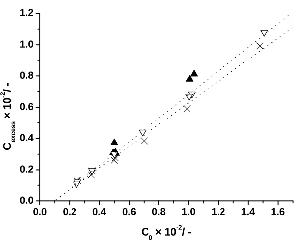
Figure 3:The calculated excess concentration of solid particles which remain in the continuous phase (Cexcess) versus the overall concentration of solid particles in water (C0) in g g-1(series I; series II ×; series III ▲). The dotted lines are Eqs. 17 and 18
Equations 17-18
Table 1:Summary of the various formulations used for the Pickering miniemulsion polymerisations of styrene stabilised by Laponite clay
Table 2:Summary of the various formulations used for the additional Pickering miniemulsion polymerisations of styrene stabilised by Laponite clay
Figure 4: Monomer conversion (xM) versus time (min) for Pickering miniemulsion polymerisations of styrene stabilised with Laponite clay
Equations 19-10
Figure 5: The ratios of the values obtained from Eq. 20 for the Pickering miniemulsion polymerisations and those obtained from Eq. 21 for the ordinary bulk polymerisation of
styrene, i.e. φ[R], as a function of monomer conversion.
Table 1: Pickering Miniemulsion Polymerisations of styrene stabilised by Laponite Clay Table 2: Additional Pickering Miniemulsion Polymerisations of styrene stabilised by Laponite Clay
Table 3:Pickering Miniemulsion Polymerisations of various monomers stabilised by Laponite Clay
Chapter 5:
Scheme 1-4
Figure 1:Correlation between the theoretical excess of clay and the quantity of clay added. The order of increasing concentrations of soap goes from 1-4 for SDS, 1-3 for CTAB and a single run with DODAB (0.3 g/L). The result missing from the CTAB experiments is the 3.0 g/L since it coagulated upon emulsification.
Figure 2: Graph showing the relative rate of polymerisation compared to bulk. (φ[R]) vs.
the conversion (Xm). The amounts of surfactants used are displayed for 100 mL of water.
Figure 3: Graphical representation of soap double layer formation on clay platelets
Figure 4: Decomposition rate of KPS over time at different temperatures. The grey region denotes the region in which it is known our clay miniemulsion system is stable for SDS
Figure 5: Decomposition rate of V50 at different temperatures along with the grey region in which it is known our clay miniemulsion system is stable for CTAB and DODAB
Figure 6:Zeta potential measurements of Ludox TM-40 at various pHs Scheme 5-6
Figure 7:Ludox miniemulsion after polymerisation using 0.003g SDS. Large spheres are PS latex particles. Small spheres are Ludox. Scale bar 200 nm
Figure 8: Figure showing armoured PMMA latex particles with Ludox as stabiliser. Scale bar is 200 nm
Figure 9: FE-SEM image of a poly(methyl methacrylate) latex prepared via emulsion polymerisation at pH 10.0 in the presence of Ludox TM-40.
Figure 10:FE-SEM image of a poly(methyl methacrylate) latex armoured with Ludox TM-40 prepared via emulsion polymerisation at pH 3.0.
Figure 11:FE-SEM images of latexes generated from using a) ethyl methacrylate b)n -butyl methacrylate c) styrene. Scale bars are 200 nm in all cases
Equation 1-3
Figure 14:TEM image of poly(methyl methacrylate) armoured latex particles with a shell of poly(n-butyl acrylate)
Figure 15: TEM image showing poly(methyl methacrylate) armoured Latex particles with a shell of poly(ethyl methacrylate).
Table 1: Experimental data and results
Chapter 6:
Figure 1:Thermal gravimetric analysis curves obtained for the 7 samples analysed. The graph has been normalised by removing the mass of left over material, in order to make comparisons easier.
Figure 2:Correlation between the proportions of high stability material relative to the amount of polymer in contact with clay
Figure 3:Schematic illustration of the theoretical volumes taken up by the high and low temperature material
Figure 4:Correlation between the percentage of coke deposits and the surface area to volume ratio of the latex particles
Figure 5:Figure showing a cross-section of the honeycomb material created by heating a film of our smallest clay-armoured latex particles at 600 °C for several hours
Figure 6: Summary of the processes involved in a PSA when an adherent is removed from the surface. a through to f show increasing distance of the probe from the substrate.
Figure 7: Adhesion stress-strain curves of PBA physically blended with Laponite. An example showing the adhesive improvement at Laponite concentration of 0.15 % (maximum achieved) and a reduction in performance at high Laponite content (1.0 %) are shown here.
Figure 8: Adhesion stress-strain curves of PBA physically blended with PLA. No improvement at low PLA content, but better adhesion at high PLA content
Figure 9:Adhesion stress-strain curves of PBA/PLA-Clay nanocomposite.
Figure 10:The synergy effect of armoured soft hybrid particles on adhesion energies of nanocomposite adhesives.
Figure 11: Adhesion stress-train curve comparison of PBA, PBA/PLA, PBA/clay, PBA/PLA + free clay and PBA/PLA-clay nanocomposite with the same amount of PLA (2.45 %) or clay content (0.25 %) as in PBA/PLA-clay nanocomposite.
Figure 12: Dynamic mechanical analysis of PBA, PBA/Clay (with the same amount of clay, 0.25 %, as in PBA/Clay nanocomposite) and PBA/PLA-Clay nanocomposite. Table 1:Viscoelasticities of adhesive blends with different fillers
Chapter 7
Figure 1: Basic reaction scheme for a free radical polymerisation reaction using a vinyl monomer
Equation 1-7
Figure 2:The one electron step involved in the redox reaction between cumyl hydroperoxide and Fe2+
Figure 4:Plot showing the relative intensities at multiple angles for different particle sizes using Mie theory
Figure 5:Schematic representation of a confocal microscope.
Figure 6:Schematic representation of a probe-tack stress strain curve Equation 8-9
Acknowledgements
I would like to thank the entire Bon group who I have worked with for making my time fun and interesting. I would like to thank Catheline Colard for her help with the Ludox systems. I also want to Thank Assoc. Prof. Stefan Bon for his continued encouragement and help through out my PhD who without there would probably be no completed thesis. I would like to thank Wang Tao and Prof J. Keddie for the use of their facilities at the University of Surrey and all the help and input given in the work with the pressure sensitive adhesives. I acknowledge S. York, S. Schumann and Dr. N. Wilson for help with microscopy, D. Hammond for running thermal gravimetric analysis measurements on my samples and the EPSRC for funding. I would like to thank P. Wright and K. Randell for transport arrangements, Capt. S. Colver for his literary suggestions, E. Colver for her valued logical thinking and focus. Most importantly I would like to thank H. Keens for keeping me sane and giving constant support.
Declaration
I declare that I am the major contributor to all work in this thesis except for the work in chapter 3 on the jamming of the interface of droplets passed through a capillary which was done in collaboration with S. Mookhoek from DELFT, NL. Also the pressure sensitive adhesives section in chapter 6 which was done in collaboration with Professor J. Keddie and Wang Tao from Surrey University, UK. Lastly the zeta potential graph (Chapter 5, Figure 6) was produced by C. Colard. Any work previously published is referenced on the opening page of each chapter.
Summary
Abbreviations
acrylonitrile (ACN)
2,2'-azobisisobutyronitrile (AIBN)
butyl acrylate (BA)
butyl methacrylate (BMA)
cation exchange capacity (cec) cetyl trimethyl ammonium
bromide (CTAB)
dodecylbenzenesulfonic acid, sodium salt
(DDBSS)
dynamic mechanical thermal analysis
(DMTA)
dimethylaminoethyl methacrylate (DMAEMA) dioctadecyl dimethyl ammonium
bromide
(DODAB)
di-tert-butylperoxyoxalate (DTBPO)
divinylbenzene (DVB)
ethyl methacrylate (EMA)
high internal phase emulsion (HIPE) interpenetrating network (IPN)
potassium persulfate (KPS)
lauryl acrylate (LA)
lauryl methacrylate (LMA)
methyl acrylate (MA)
methacrylic acid (MAA)
medium internal phase emulsion (MIPE)
nuclear magnetic resonance (NMR)
polydispersity (PDi)
pressure sensitive adhesive (PSA)
sodium dodecyl sulphate (SDS)
field emission – scanning electron microscope
(FE-SEM)
sorbitan monolaureate (SPAN 20)
sorbitan monooleate (SPAN 80)
styrene (St)
single walled carbon nanotube (SWNT) transmission electron microscope (TEM) thermal gravimetric analysis (TGA) 2,2'-azobis(2-methyl
propionamidine) dihydrochloride (V-50) 2,2'-azobis(2,4-dimethyl
valeronitrile)
Materials
Methyl methacrylate, methyl acrylate, n-butyl methacrylate, n-butyl acrylate, ethyl methacrylate, lauryl methacrylate, lauryl acrylate, octyl acrylate, divinylbenzene, methacrylic acid, ethylene glycol dimethacrylate, acrylonitrile, styrene and 2-ethylhexyl methacrylate were purchased from Aldrich or subsidiary companies at 99% (except DVB which is 80% technical grade) or greater purity and were passed through a basic alumina (activated, basic, Brockmann I) column before use in order to remove inhibitors. Hostasol methacrylate was kindly provided by the group of Prof. D. Haddleton. n-Hexadecane was purchased from Aldrich, and sodium chloride was purchased from BDH, both at reagent-grade purity. Ammonia was purchased from Fisher at S.G. 0.88 (35%) concentration in water. All were used as supplied. The clay used was Laponite RD and was kindly donated by Rockward Additives Ltd. AIBN, V-65 and V-50 were kindly donated by Wako Initiators and were used as supplied. Ludox TM40 colloidal silica (40 wt% suspension in water), sodium hydroxide (NaOH), potassium persulfate (KPS) p.a.>99.0% and hydrochloric acid aqueous solution (HCl (aq)) analaR, and sodium dodecyl sulfate (SDS) were purchased from BDH. Cetyltrimethylammonium bromide 99+% (CTAB) and dioctadecyldimethylammonium bromide (DODAB) were purchased from ACROS organics. Olive oil was obtained from the shelf of the local
Costcutter supermarket. Oxalyl chloride puriss., ≥99.0%, purum, packed
Chapter 1: Introduction to Pickering Stabilisation
1Manipulation of materials in order to build useful structures has been done for thousands of years. When you start from a bulk material you can shape it either by carving or etching, or via molding. These shaped objects can then be used as building blocks to subsequently form more complex materials, made via assembly of the individual parts. The preparation of the building blocks follows a top-down approach. This method of producing materials can become complex if the targeted object and individual building blocks become small,i.e. of micro- or nano-sized dimensions. Interest in small materials was initiated by a ground breaking lecture given by physicist Richard Feynman in 1959 entitled ‘‘There is plenty of room at the bottom’’ in which he addressed the problem of manipulating and controlling things on a tiny scale, with the example of printing the entire 24 volumes of Encyclopedia Britannica on the head of a pin. To easily manipulate materials at this tiny scale a different approach must be used and is called bottom-up, and has great potential. In this, the individual building blocks are synthesized via chemical procedures. This can be a complex task in itself, but the real challenge comes from arranging these individual components into the desired suprastructure. The latter process is referred to as assembly, and there are two ways to achieve this, either directed or spontaneous.
by capillarity was gained. This resulted in a number of different suprastructures.8 A similar approach was undertaken by Suzuki et al., who, through self assembly of particles with two hemispheres of different wettabilities, created “necklaces” of linked particles.9 On a much smaller scale, molecules can be tuned to self-assemble via hydrogen bonds to create hydrogen-bonded polymers which will self-heal.10In a similar vain much work has been conducted on using DNA to cause selective self-assembly. By tuning the hydrogen bonding sites on a particle with amino acids it has been shown that it is possible to arrange particles with a desired partner.11-13 A more widespread and simple technique for spontaneous self-assembly is the use of Pickering stabilisation14,15, this is where solid colloidal particles will self assemble onto an interface in order to reduce the overall energy of the system. Weitz and co-workers published a paper on the stabilisation of droplets and coined the term “colloidosome” to describe the suprastructure16. Although this lacks the control of some of the other methods, this process has been known for over a century and has recently grown into a big area of interest for many researchers and industries around the world and has great versatility for making different materials. The work I will be reporting in this thesis, uses Pickering stabilisation as its basis.
Brownian motion. Colloidal particles are generally in the size range of 10-1000 nm and can come in many types. Natural colloids can be clays, proteins or even bacteria. Synthetic colloids can be organic; microgel particles or dendrimers. They can also be inorganic i.e. metal (oxide) nanoparticles like CdSe or TiO2.
The theory behind a Pickering emulsion is that the particles adsorb at the interface and form a colloidosome in order to lower the total interfacial energy. This is seen by looking at the energy of the interfaces available: Pieranski examined the 3 energies of the created interfaces; particle/oil(p/o) particle/water(p/w) and oil/water(o/w)17.
) ˆ 1 ( 2 2 /
/ R z
EP O P O Equation 1
) ˆ 1 ( 2 2 /
/ R z
EP W P W Equation 2
) ˆ 1 ( 2 2 /
/ R z
EO W O W Equation 3
Where σ is the respective surface tension and ž=z/R is the displacement
(z) of the particle from centre of particle radius R. This allows the calculation of the position of the particle at its lowest energy, and in turn allows the calculation of the type of emulsions most favourably formed:
P W W O W O init R
E / / 4 2 / Equation 4
) (
2 )
( / 2 2 / /
/W OW W P OP
O
final R R
E Equation 5
This in turn shows that the energy has been reduced and equation 5 can be
)] ( 2 [ / / / 2 P W P O W O init
final E R
E Equation 6
This equation can then be used to calculate the total amount of energy saved from the interface change18. Figure 1 shows the energies for a standard system involving water and n-hexadecane as the two phases and 200 nm polystyrene particles. The calculated energies were divided by Brownian motion (kBT) in order to make these values dimensionless.
-1.0 -0.5 0.0 0.5 1.0
0.2 0.3 0.4 0.5 0.6 0.7 0.8 0.9 1.0 E x 1 0 6 / -z
0/
-Figure 1: Graph showing the energy E, the calculated energy divided by Brownian motion kBT, at different displacements, z0, of the particle, where z=-1 is fully in the n-hexadecane phase and 1 is fully in the water phase
[image:19.595.123.482.292.563.2]implies that if the particle is more stable in one phase the minimum could be greater or less than +/-1, respectively.
This approach does not take into account the angle that the adsorbed particle will form at the interface when a droplet is formed. Binks has shown that the energy required to remove a particle from an interface is19:
2 2
) cos 1
(
R
E Equation 7
Whereγ is the interfacial tension between the water and oil phases andθ
is the contact angle made between oil and particle (seeFigure 2):
Figure 2: Diagram showing a particle at an interface and its contact angle.
The final method for calculating the stabilisation energy adds an extra energy term to the interfacial stabilisation. Another stabilising/destabilising effect is that of image charges. Image charges are a theoretical way of calculating the charge density around an interface (for example a particle). Instead of a boundary of charge, the charges are separated into points. These points are called image charges and, when added up, they completely counter the charge on the particle. The position and size of an image charge can be calculated by Green’s
θ
γ
θ
creating repulsion. Unrefuted evidence of this stabilising force was shown by van Blaaderen, who showed that, in a generated colloidal crystal of poly(methyl methacrylate) spheres in oil, particles form a monolayer touching (but not imbedded in) the interface between the oil and water.55 This is attributed to the attraction due to the image charge, since the polymer spheres are not wetted by the water. The role of image charges in the stabilisation of colloidal systems has been expertly reviewed recently.23
rigidly attached to the colloid, while the diffuse layer is not. As a result, the electrical potential at this junction is related to the mobility of the particle and is called the zeta potential. Although zeta potential is an intermediate value, it is sometimes considered to be more significant than surface potential as far as electrostatic repulsion is concerned.24 Typically particles with zeta potentials of greater than +30 mV or less than -30 mV are colloidally stable. These are considered to be the minimum values before the energy of Brownian motion is strong enough to force the particles to become close enough for the Van der Waals forces to overcome the repulsion. When a colloidal particle is used as a Pickering stabiliser it actually benefits the system for the zeta potential to be between +/-30 mV. This is because the particle has to sit on the interface between the two phases, and if the particle is too stable in one phase this will not happen; this is equivalent to the minimum in Figure 1 being
outside -/+1.
was modified by changing the temperature of the system. This is due to the fact PNIPAM has an LCST of 32 °C in aqueous medium27. In addition the charge on the MAA groups can be changed by modifying the pH of the system as the carboxyl groups become deprotonated above pH 4. Li and Stover have reported a doubly pH-responsive system using alumina-coated silica particle and charged potassium hydrogen phthalate species, which only binds to the silica at pH 3.5-5.5. Thus for pH lower than 3.5 or higher than 5.5 the Pickering emulsions are not stable.28The solution pH has also been used to control the type of droplet that is stabilised. Schmitt
et al. showed that by using the same particles and varying the solution pH, small sparsely-covered droplets or large well-covered droplets could be made.29 Wettability isn’t the only factor that can control stability. Fuller et al. showed in some ground breaking work that magnetic particles could be used as a Pickering stabiliser. This gives an emulsion which can be reversibly broken via an external stimulus, and also the Pickering particles can be easily reclaimed.30
coalescence Arditty et al. created very monodisperse droplets of sizes ranging from micrometre to millimetre sizes.29,33 Limited droplet coalescence works by creating more interface than the Pickering stabiliser can cover. The droplets then coalesce until enough interface is covered. Another industrial application has been shown by Syngenta who released a patent on the use of solid-stabilised droplets of pesticides.34 Later we will discuss solid-stabilised porous materials with structures not accessible using usual conventional surfactants, which are currently being investigated for commercial use.35In a similar vein Clegget al.have created stable bicontinous emulsions which are only stable due to the high stabilising force of Pickering.36-38
Table 1:Scaffolding Strategies
Physical Scaffolding Chemical Scaffolding
Solidification of inner liquid phase
Jamming and/or 2D crystallisation
Autohesion/Film formation
Physisorption of polymers
Formation of an Interpenetrating Polymer Network (IPN)
Interfacial polymerisation
Chemisorption of polymers
to the interface. More examples of jammed structures are given in a later chapter. In the first paper to coin the term “colloidosome”, Weitz et al.
managed to stabilise latex based Pickering emulsions by autohesion. Colloidosomes were prepared by heating above the glass transition temperature (Tg) of the latex particles. This allowed deformation and polymer-polymer interdiffusion to reinforce the latex superstructure. 49 One of the simplest ways of physically binding the building blocks to one another at the droplets interface is by physisorption of polymers. Weitz showed a very elegant way of doing this49 when a droplet containing poly-L-Lysine was stabilised by colloidal latex particles; polymer chains then adsorb onto the latex particles, locking neighbours together, giving a rigid yet flexible scaffold.
chemisorption of reactive polymers to colloidosomes made from inorganic pigments.54
(1) A. Ashkin, J. M. D., J. E. Bjorkholm, and S. Chu,Opt. Lett.1986,11, 288. (2) Eric, R. D.; Gabriel, C. S.; Matthew, T. D.; Steven, A. S.; David, G. G.Rev. Sci. Instrum.2001,72, 1810-1816.
(3) Velev, O. D.; Bhatt, K. H.Soft Matter2006,2, 738-750.
(4) Winkleman, A.; Gates, B. D.; McCarty, L. S.; Whitesides, G. M.Adv. Mater.2005,17, 1507-1511.
(5) Koch, R. L., IIProducts Finishing (Cincinnati, OH, United States)1967,31, 45-53.
(6) Lee, J. A.; Meng, L.; Norris, D. J.; Scriven, L. E.; Tsapatsis, M.Langmuir
2006,22, 5217-5219.
(7) van Blaaderen, A.; Ruel, R.; Wiltzius, P.Nature1997,385, 321-324. (8) Bowden, N.; Choi, I. S.; Grzybowski, B. A.; Whitesides, G. M.J. Am. Chem. Soc.1999,121, 5373-5391.
(9) Suzuki, D.; Tsuji, S.; Kawaguchi, H.J. Am. Chem. Soc.2007,129, 8088-8089.
(10) Cordier, P.; Tournilhac, F.; Soulie-Ziakovic, C.; Leibler, L.Nature2008, 451, 977-980.
(11) Kim, A. J.; Biancaniello, P. L.; Crocker, J. C.Langmuir2006,22, 1991-2001.
(12) Liang, H.; Angelini Thomas, E.; Ho, J.; Braun Paul, V.; Wong Gerard, C. L.J. Am. Chem. Soc.2003,125, 11786-7.
(13) Tkachenko Alexei, V.Phys. Rev. Lett.2002,89, 148303. (14) Ramsden, W.Proc. R. Soc.1903,72, 156-164.
(15) Pickering, S. U.Journal of the Chemical Society, Transactions1907,91, 2001-21.
(16) Dinsmore, A. D.; F., H. M.; Nikolaides, M. G.; Marquez, M.; Bausch, A. R.; Weitz, D. A.Science2002,298, 1006-1009.
(17) Pieranski, P.Phys. Rev. Lett.1980,45, 569.
(18) C. Zeng, H. B., A. D. DinsmoreSolid State Commun.2006. (19) Binks, B. P.; Lumsdon, S. O.Langmuir2000,16, 8622-8631.
(20) Jackson, J. D.Classical Electrodynamics; Third ed.; John Wiley & Sons, Inc., 1999.
(21) Klein, R.; Von Grunberg, H. H.Pure Appl. Chem.2001,73, 1705-1719. (22) von Grunberg, H. H.; Helden, L.; Leiderer, P.; Bechinger, C.J. Chem. Phys.2001,114, 10094-10104.
(23) Hatlo, M. M.; Lue, L.Soft Matter2008,4, 1582-1596. (24) http://www.malverninstruments.com.
(25) Amalvy, J. I.; Armes, S. P.; Binks, B. P.; Rodrigues, J. A.; Unali, G. F. Chem. Commun. 2003, 1826-1827.
(26) Ngai, T.; Behrens, S. H.; Auweter, H.Chem. Commun.2005,3, 331-333. (27) Wu, C.Polymer1998,39, 4609-4619.
(28) Li, J.; Stover, H. D. H.Langmuir2008,24, 13237-13240.
(29) Arditty, S.; Whitby, C. P.; Binks, B. P.; Schmitt, V.; Leal-Calderon, F.Eur. Phys. J.: E2003,11, 273-281.
(30) Melle, S.; Lask, M.; Fuller, G. G.Langmuir2005,21, 2158-2162. (31) Salonen, A.; Muller, F.; Glatter, O.Langmuir2008,24, 5306-5314. (32) Perro, A.; Reculusa, S.; Ravaine, S.; Bourgeat-Lami, E.; Duguet, E.J. Mater. Chem.2005,15, 3745-3760.
(33) Arditty, S.; Schmitt, V.; Giermanska-Kahn, J.; Leal-Calderon, F.J. Colloid Interface Sci.2004,275, 659-664.
(34) Fowler, J.; (Syngenta Participations AG, Switz.). Application: WO WO, 2008, p 43pp.
(36) Clegg, P. S.; Herzig, E. M.; Schofield, A. B.; Horozov, T. S.; Binks, B. P.; Cates, M. E.; Poon, W. C. K.J. Phys.: Condens. Matter2005,17, S3433-S3438.
(37) Clegg, P. S.; Herzig, E. M.; Schofield, A. B.; Egelhaaf, S. U.; Horozov, T. S.; Binks, B. P.; Cates, M. E.; Poon, W. C. K.Langmuir2007,23, 5984-5994.
(38) Clegg, P. S.; Herzig, E. M.; Schofield, A. B.; Egelhaaf, S. U.; Horozov, T. S.; Binks, B. P.; Cates, M. E.; Poon, W. C. K.Los Alamos Natl. Lab., Prepr. Arch., Condens. Matter2006, 1-12
(39) Cayre, O. J.; Noble, P. F.; Paunov, V. N.J. Mater. Chem.2004,14, 3351-3355.
(40) Chen, T.; Colver, P. J.; Bon, S. A. F.Adv. Mater.2007,19, 2286-2289. (41) Liu, Y.; Chen, X.; Wang, R.; Xin, J. H.Mater. Lett.2006,60, 3731-3734. (42) Jeng, J.; Chen, T.-Y.; Lee, C.-F.; Liang, N.-Y.; Chiu, W.-Y.Polymer2008, 49, 3265-3271.
(43) Bon, S. A. F.; Cauvin, S.; Colver, P. J.Soft Matter2007,3, 194-199. (44) Wiley, R. M.; (Dow Chemical Co.). US, 1959.
(45) Wiley, R. M.; (Dow Chemical Co.). US, 1959. (46) Wiley, R. M.J. Colloid Sci.1954,9, 427-437. (47) Wiley, R. M.; (Dow Chemical Co.). DE, 1957.
(48) Subramaniam, A., B.; Abkarian, M.; Stone, H. A.Nat. Mater.2005,4, 553-556.
(49) Gordon, V. D.; Chen, X.; J.W., H.; Bausch, A. R.; Marquez, M.; Weitz, D. A.J. Am. Chem. Soc.2004,126, 14117-14122.
(50) Skaff, H.; Lin, Y.; Tangirala, R.; Breitenkamp, K.; Boker, A.; Russell, T. P.; Emrick, T.Adv. Mater.2005,17, 2082-2086.
(51) Lin, Y.; Skaff, H.; Boker, A.; Dinsmore, A. D.; Emrick, T.; Russell Thomas, P.J. Am. Chem. Soc.2003,125, 12690-1.
(52) Mookhoek, S. D.; Blaiszik, B. J.; Fischer, H. R.; Sottos, N. R.; White, S. R.; van der Zwaag, S.J. Mater. Chem.2008,18, 5390-5394.
(53) Shen, S.-L.; Wu, W.; Guo, K.; Meng, H.; Chen, J.-F.Colloids and Surfaces A: Physicochem. Eng. Aspects2007,311, 99-105.
(54) Shirley, I. M.; Heming, A. M.; Bon, S. F.; Cauvin, S. M. P.; (Syngenta Limited, UK). Application: WO, 2008, p 13pp.
Chapter 2: Water-in-oil Pickering High Internal Phase
Emulsions – Fabrication of Poly”colloido”(HIPE)s
†In the previous chapter we briefly discussed creating Pickering structures with the dispersed phase being a hydrophobic monomer and the external continuous phase being water, which can be polymerised to give individual armoured particles. Prime examples were our previous work in preparing hollow supracolloidal structures using microgels as solid-stabilizers which are scaffolded by interpenetrating polymer networks (IPNs)1, and our silica-armoured polymer capsules,2 along with many other examples shown in the previous chapter. However, it is also possible, by tuning the wettability of the Pickering stabiliser, to create either water-in-air or water-in-oil emulsions. Binks showed this by changing an air-in-water foam into a water-in-air “dry water” system. This was done by changing the wettability of the stabilising silica particles, thereby causing a transitional inversion, or by increasing the water and air ratio causing a catastrophic inversion.3 Tervoort et al. has shown a simple method to modify metal oxide nanoparticles in order to create water-in-oil emulsions.4 By doing this one creates individual droplets of water in a continuous phase of monomer. Solidification of the continuous phase, in the present case through polymerisation, would create a porous monolithic structure, generically referred to as cellular materials. Different types of porous materials have been made using this
1537-system for many years:5 These materials can have a porous structure, which consists of closed cells and/or open cells, with the latter referring to a system in which the pores are interconnected. This porous feature makes these materials interesting for a wide range of applications, such as supports for catalysts (high surface area), mechanical scaffolds e.g.for tissue growth, materials for electrical, sound and heat insulation (high porosity), 3D batteries and optical band-gap materials.6Pineet al.showed the preparation of uniform macro-porous silica, titania and poly(acrylamide) which were synthesized around a concentrated dispersion of liquid emulsion droplets with narrow particle size distribution.7 Titania foams have been shown to have excellent photocatalytic activity8 and, using the method developed by Pine’s group, can be used to produce photonic crystals.9 Binks reported the preparation of macroporous silica using solid-stabilised/Pickering emulsions as templates. These materials had either cellular, bicontinuous or colloidal gel type morphologies, depending on the type of emulsion used.10 More recently, Sun et al. showed by the vapour deposition of water onto a hydrophobic oil that Pickering honeycombs could be produced using silica as stabiliser.11 Sherrington and co-workers have produced numerous examples of porous supports for reactions.39
activity or functional separation. Cellular polymers formed by creation of a High Internal Phase Emulsion (HIPE) and subsequent polymerisation of the continuous phase, are often referred to as poly(HIPE), and were pioneered by Bartl,12,13 Lissant14 and Barby.15 A High Internal Phase Emulsion, or gel emulsion, has a volume fraction for the dispersed phase greater than 0.74, which is the maximum packing density for monodisperse hard spheres. The porous polymer materials are generally formed via templates of water-in-monomer gel emulsions stabilised with surfactants such as sorbitan monooleate (SPAN 80),16 or a mixture of nonionic, anionic, and cationic surfactants: sorbitan monolaureate (SPAN 20), dodecylbenzenesulfonic acid sodium salt (DDBSS), and cetyltrimethylammonium bromide (CTAB).17
with surfactants and then using the particles in the same way as surfactants are used in normal HIPE manufacture.23,24
Figure 1:Three possible designs using two different particles as Pickering stabilisers of
cellular polymer monoliths.2DProjections are from the side (y,z-plane). In example A the particles are randomly distributed over each water droplet, or cell; B shows a random blend of two Pickering emulsions with each droplet stabilised by only one type of particle; in C we pack one Pickering emulsion on top of the other creating distinct zones or layers, in the cellular monolith.
The synthesis strategy can be set out in three consecutive steps:
(i) Microgels of submicron dimensions synthesised via miniemulsion polymerisation were used as solid stabilisers to create Pickering water-in-oil emulsions.1,25,26 When a good solvent for the polymer is used, the crosslinking of these latex particles is essential, in order to prevent disintegration via swelling once assembled at the liquid-liquid interface, which will ultimately result in loss of Pickering stabilization. For the poly(HIPE)s containing two different types of particle stabilisers we used both hostasol-labelled and non-labelled microgels. As a tag we used 2-(6-methacryloyloxyhexyl)-thioxantheno[2,1,9-dej]iso-quinoline-1,3-dione, a hostasol methacrylate derivative.27 A variety of monomers were used to make up the oil phase, such as divinylbenzene, mixtures of styrene/divinylbenzene, n-butyl and mixtures of n-lauryl methacrylate/ethylene glycol dimethacrylate. The oil phase also included
2,2'-azobis(2,4-dimethyl valeronitrile) (V-65). The microgel-stabilised water-in-oil emulsions were generated by vigorous handshaking. Note that the microgels are dispersed in the aqueous phase prior to mixing. Also in some cases the room temperature initiator, di-tert-butylperoxyoxalate, was used when monomer and water evaporation, or the formation of air bubbles, caused the creation of large voids or induced destabilisation.
(ii) The Pickering emulsions were allowed to settle via gravitation/buoyancy, typically for about 1 hour with occasional gentle shaking to increase the packing efficiency. According to Stokes’ law (1851) this is the time needed for a “hard sphere” of water with a
diameter of 10 μm to descend 4.36 cm in toluene, conditions which are
easily met for our monolith designs:
2
) (
9 2
R g VS p f
Equation 1
Equation 1 shows the equation that corresponds to Stokes’ law. Where Vs is the terminal velocity of the droplet of water (m/s), pis the density of
the water droplet (998 kg/m3),
f
is the density of the continuous medium (taken to be toluene at 867 kg/m3), µ is the viscosity of the continuous medium (0.59 x 10⁻³Pa s), g is the acceleration due to gravity (9.81 m s-2) and R is the mean radius of the droplet (m).
(yellow) and non-labelled (white) microgels dispersed in the water phase was used for system A. The random blend of emulsion droplets each stabilised with one type of particle,B, was generated by gentle mixing of two pre-made Pickering emulsions via tumbling by hand of the vials. For the layered systems, C, one high internal phase Pickering emulsion template was carefully placed on top of the other using a pipette.
Figure 2: Collection of poly(n-butyl methacrylate) based cellular polymer monoliths produced via Pickering high internal phase emulsions after removal of reaction vial. The monoliths are placed upside down. The clear bottom layer in the image is bulk polymer
Pickering-stabilised emulsion droplets occurs on the time scale of the in situ polymerisation, otherwise all cells would show some fluorescent emission. These findings are to be expected, since the energy well at the liquid-liquid interface is too large for the particles to escape.
Figure 3:Cumulative projection of z-slices obtained via dual channel confocal microscopy. The first channel (white) represents the reflected light signals of the Pickering poly(HIPE), whereas the second channel (yellow) exclusively shows the fluorescent emission
When various monomers are used as the continuous phase, different properties can be imbibed into the structure. For instance, upon evaporation of the water under vacuum the monoliths made from poly(n -butyl methacrylate) buckled. Clearly, the pure poly(n-butyl methacrylate) scaffold is not robust enough to withstand pressure differences/capillary forces upon drying.
Permanent shape deformation of the cellular monoliths were not observed when 10.1% divinylbenzene was used as a comonomer, or in the cases of pure divinylbenzene or its mixtures with styrene, or in the case of a mixture of n-lauryl methacrylate and ethylene glycol dimethacrylate (4.7 wt%). The pure divinylbenzene monolith gave the highest porosity of 87 %. This is probably due to the DVB having the highest density change during polymerisation, causing volume contraction of the continuous phase while the internal phase remains the same size.
The latter n-lauryl methacrylate plus ethylene glycol dimethacrylate cellular monolith was very flexible and spongy. Elastomeric poly(HIPE) materials have been made before by Cameron and Sherrington using conventional surfactants.29
An important parameter to control in our system is the cell size. As in normal surfactant poly(HIPE) systems this can be controlled by varying the amount of microgel particles used. As a crude indication for cell dimensions, i.e. the diameter of the Pickering-stabilised emulsion droplets, we can use equation 2:
In which Cov represents the coverage expressed as the ratio of the effective area covered by the particle stabilisers and the total area of the water droplet, wpart is the weight fraction of particle stabilisers used with
respect to the amount of water phase, ρwaterandρpartbeing the densities of the water phase and the microgel particles in g cm-3, and D and dpart are
the diameters of the emulsion droplet and the particle stabilisers in μm.
In case of the preparation of a purely divinylbenzene-scaffolded cellular monolith (see experimental) we assume full coverage, Cov = 1. This would in theory produce a poly(HIPE) having cells with an average
diameter of approximately 400 μm. From figure 6 it can be observed that
this approximate value is of the right order of magnitude.
part d water part part w Cov
D
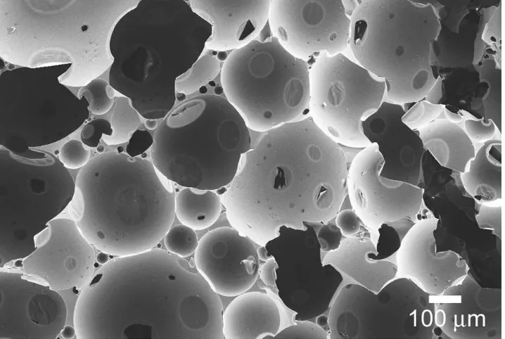
Figure 6:FE-SEM image of cellular monoliths scaffolded with poly(divinyl benzene).
The cellular structure in our Pickering Poly(HIPE)s can be open and/or closed. In the case of the poly(divinylbenzene) monoliths, we see from FE-SEM analysis (Figure 6) that cells sometimes are interconnected, but in most cases a thin film is present at the points of contact of two cells. This thin film occasionally is broken, as can clearly be observed from the image. It seems logical that these films are present since Pickering emulsions are highly stable, even upon direct contact. We envisage that these films could be used as pressure release valves in two pack systems where each individual cell is filled with different reagents, provoking a desired chemical reaction upon rupture.
between two cells. The latter was recently observed by Horozov and Binks.30 In all of our cases we have not been able to find bridging monolayers.
As clearly can be seen from Figure 7, microgel building blocks are present at both sides of the interconnecting scaffolding polymer. The absence of monolayer films could however be an artefact, as these films would be very thin and could quite easily break under the stresses of drying and sample preparation. This film breaking was observed in some cases when we tried to examine some films more closely under SEM.
[image:44.595.149.464.160.368.2]It is also possible, due to the high stability of these emulsions, to increase their porosity by forcing greater packing density by putting the liquid HIPE into a centrifuge tube and spinning the emulsion and forcing the heavier water to the bottom of the tube. It was found that our emulsions could withstand forces up to 3000 times gravity. By removing the
resulting excess monomer forced to the top, poly(HIPE) materials could be made with 80-90 % porosity without the need for a 1 hr settling period. These materials however were not as robust as the HIPEs made previously. This can be seen in Figure 8.
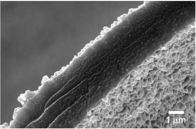
Figure 8: FE-SEM image showing a polymerised HIPE after centrifugation. Of note are the thin walls which can be seen to have crumbled.
Figure 9:a) FE-SEM image showing the solid polymer HIPE protruding from a PTFE tube and b) the porous end of the HIPE
droplets. Another issue which can be seen in this system, as can be seen from Figure 8a, is the contraction of the continuous phase during polymerisation. This causes the HIPE material to pull away from the inside of the capillary. This problem can be overcome in a couple of ways; either by modifying the inside of the capillary to polymerise along with the continuous phase, or by making the material of the capillary from a material that will swell with monomer to create an interpenetrating network of polymer chains.
Conclusion
It has been shown that Pickering-stabilised Poly(HIPE)s can be made with different morphologies that are not possible with standard surfactant-stabilised HIPEs. It has also been shown that there is potential use for these structures to be used in microfiltration. More work is being done in collaboration with Dr. Emily Hilders’ group in Tasmania on overcoming the remaining obstacles involved in this application.38
Experimental
General conditions
Sigma 12151 adapter at 1000g for 2 times 5 min. Excess organic phase was removed with a pipette. Dynamic light scattering and zeta potentials measurements were performed on a Malvern Instruments Zetasizer 3000HSA. FE-SEM images were taken on a ZEISS supra 55VP FEGSEM under high vacuum EHT = 5 kV WD = 4 mm. Confocal imaging was performed on a ZEISS LSM 510 confocal microscope with a 458 nm, 477 nm and 488 nm wavelength argon ion laser with two active channels: One with a LP 505 filter (detects fluorescence) and another with no filter (detects reflectance).
Pickering Particle Formation
After ten minutes the mixture was subjected to positive nitrogen pressure and V-044 initiator (0.0542 g, 1.6x10⁻⁴ mol) dissolved in deoxygenated water (2 mL) was injected into the emulsion. After 24 hrs the mixture was and allowed to cool. Particle formed had Z average=153 nm PDi=0.03, determined by dynamic light scattering.
Figure 10:FE-SEM image of DVB-poly(methyl methacrylate) latex spheres used for generating poly(HIPEs). Scale bar 200 nm
Inverse Pickering Emulsion Formation
top with a pipette. The resulting high internal phase emulsion was then allowed to polymerise at 51 ºC for 24 h. The poly(HIPE) was allowed to dry first in air and then under vacuum. This was done to remove the water. The overall porosity of this poly(HIPE) was 82%.
All other poly(HIPE) materials mentioned were formed in the same way except the monomer type was exchanged.
Synthesis of di-tert-butylperoxyoxalate:
This compound was prepared using the procedure reported by Bartlettet al28. Tert-butyl hydroperoxide (5.5 M solution, 18.85 g) dry pyridine (12
mL) and anhydrous n-pentane (120 mL) were charged into a 500 mL round bottom flask under nitrogen, which had previously been dried in an ovenset to 150 °C. This mixture was cooled below -10 °C using a solution of saturated calcium chloride cooled to just above freezing by liquid nitrogen. Oxalyl chloride (0.077 M, 9.75 g) in 80 mL anhydrous pentane was added dropwise during stirring over a period of 1 h while keeping the temperature under -5 °C. The mixture was then stirred for another 1.5 h then allowed to reach room temperature. The finished reaction mixture was filtered and the filtrate was recrystalised in frozen
n-heptane. The resulting crystals of DTBPO were filtered then collected.
decomposition. Moreover, the compound should be handled with extreme care – avoid scratching and shaking – and should always be stored in a freezer (255 K) immediately after use, preferably in a plastic container.
O HO Cl
O Cl
O
O O O
O O
O
+ + HCl
Figure 11:Schematic showing the reaction to form the low temperature DTBPO initiator
Yield: 30%
H1NMR: 300 Hz (CDCl3) δ 7.2600 (s, CDCl3), 1.3707 (s, 18H, all H’s), 1.2658 (s, 3Heq, self-terminated radical)
(1) Bon, S. A. F.; Cauvin, S.; Colver, P. J.Soft Matter2007,3, 194-199. (2) Chen, T.; Colver, P. J.; Bon, S. A. F.Adv. Mater.2007,19, 2286-2289. (3) Binks, B. P.; Murakami, R.Nat. Mater.2006,5, 865-869.
(4) Akartuna, I.; Studart, A. R.; Tervoort, E.; Gonzenbach, U. T.; Gauckler, L. J.Langmuir2008,24, 7161-7168.
(5) Zhang, H.; Cooper, A. I.Soft Matter2005,1, 107-113.
(6) Gibson, L. J.; Ashby, M. F.Cellular Solids: Structure and properties; second ed.; Cambridge University Press, 1999.
(7) Imhof, A.; Pine, D. J.Chem. Eng. Technol.1998,21, 682-685.
(8) Zhao, Y.; Zhang, X.; Zhai, J.; Jiang, L.; Liu, Z.; Nishimoto, S.; Murakami, T.; Fujishima, A.; Zhu, D.Microporous Mesoporous Mater.2008,116, 710-714.
(9) Manoharan, V. N.; Imhof, A.; Thorne, J. D.; Pine, D. J. Adv. Mater. (Weinheim, Germany)2001,13, 447-450.
(10) Binks, B. P.Adv. Mater.2002,14, 1824-1827.
(11) Sun, W.; Ji, J.; Shen, J.Langmuir2008,24, 11338-11341. (12) Bartl, H.; Bonin, W. v.Makromole. Chem.1962,57, 74-95. (13) Bartl, H.; Bonin, W. v.Makromole. Chem.1963,66, 151-156.
(14) Lissant, K. J.; Mayhan, K. G.J. Colloid Interfac. Sci.1973,42, 201-208. (15) Barby, D.; Haq, Z. 1982.
(16) Williams, J. M.Langmuir1991,7, 1370-1377.
(17) Barbetta, A.; Cameron, N. R.Macromolecules2004,37, 3188-3201. (18) Binks, B. P.Curr. Opin. Colloid Interface Sci2002,7, 21-41.
(19) Menner, A.; Verdejo, R.; Shaffer, M.; Bismarck, A. Langmuir 2007, 23, 2398-2403.
(20) Menner, A.; Ikem, V.; Salgueiro, M.; Shaffer, M. S. P.; Bismarck, A. Chem. Commun.2007, 4274-4276.
(21) Ikem, V. O.; Menner, A.; Bismarck, A. Angew. Chem. Int. Ed. 2008, 47, 8277-8279.
(22) Studart, A. R.; Gonzenbach, U. T.; Akartuna, I.; Tervoort, E.; Gauckler, L. J.J. Mater. Chem.2007,17, 3283-3289.
(23) Zhang, S.; Lan, Q.; Liu, Q.; Xu, J.; Sun, D.Colloids Surf. Physicochem. Eng. Aspects2008,317, 406-413.
(24) Binks, B. P.; Kirkland, M.; Rodrigues, J. A.Soft Matter2008,4, 2373-2382. (25) Fujii, S.; Read, E. S.; Binks, B. P.; Armes, S. P.Adv. Mater.2005,17, 1014-1018.
(26) Ngai, T.; Behrens, S. H.; Auweter, H.Chem. Commun.2005,3, 331-333. (27) Tronc, F.; Li, M.; Lu, J.; Winnik, M. A.; Kaul, B. L.; Graciet, J.-C.J. Polym. Sci. Part A: Polym. Chem.2003,41, 766-778.
(28) Bartlett, P. D.; Benzing, E. P.; Pincock, R. E. J. Am. Chem. Soc.1960,82, 1762-1768.
(29) Cameron, N. R.; Sherrington, D. C.J. Mater. Chem.1997,7, 2209-2212. (30) Horozov, T. S.; Binks, B. P.Angew. Chem. Int. Ed.2006,45, 773-776. (31) Christenson, E. M.; Soofi, W.; Holm, J. L.; Cameron, N. R.; Mikos, A. G. Biomacromolecules2007,8, 3806-3814.
(32) Bhumgara, Z.Filtr. Sep.1995,32, 245-51.
(33) Viklund, C.; Svec, F.; Frechet, J. M.; Irgum, K.Biotechnol. Progr.1997,13, 597-600.
(34) Petro, M.; Svec, F.; Gitsov, I.; Frechet, J. M.Anal. Chem.1996,68, 315-21. (35) Peters, E. C.; Petro, M.; Svec, F.; Frechet, J. M.Anal. Chem.1997,69, 3646-9.
(36) Svec, F.; Frechet, J. M.Science1996,273, 205-11.
(37) Xie, S.; Svec, F.; Frechet, J. M.J. Chromatogr. A1997,775, 65-72. (38)
Chapter 3: Pickering Droplets – Control of Morphology
* [image:54.595.123.449.282.650.2]Non-spherical shapes are of great interest for several reasons. For instance objects with a high surface area to volume are much more effective in self healing composite materials. This can be seen by looking at the work by Whiteet al.who showed a composite material which could be used for the self healing of cracks.1
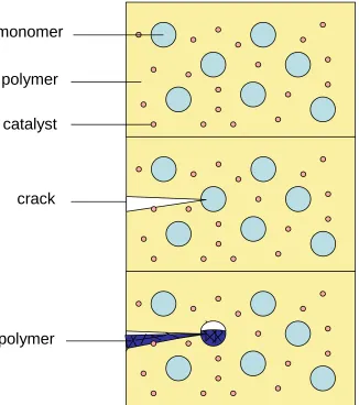
Figure 1: Reproduction of the self healing material designed by White et al. showing crack propagation and subsequent healing due to catalytic polymerisation
*
monomer
polymer
catalyst
crack
The main flaw with this system was that in order to get an effective chance of crack propagating onto a capsule a high volume % of capsule must be added. This amount of additive dramatically reduces the effectiveness of the material. By increasing the aspect area of the capsule the chance of cracks propagating onto the correct area is increased, meaning less material need be added.
Figure 2: Diagram showing the improved chance of crack propagating through an elongated capsule.
Obviously this technique would only work for materials with one direction of propagation, but this is possible for materials with a force constantly applied along one direction.
A second bonus for having a higher surface area to volume ratio is that a non-spherical object will have a high surface area with which to interact with its environment, making them of interest for substrate interactions and chromatographic applications. They are also subject to the “brazil nut effect”2,3causing separation from similarly sized spherical shapes.
part oil part oil oil part oil Cov part R R w w A A Coverage 1 Equation 1
methods of our own, utilising this jamming of interfaces to non-spherical droplets. The first method we will demonstrate relies on a microfluidic approach by passing spherical oil droplets dispersed in water through a long narrow cylindrical tube or capillary with internal diameter being considerably smaller that the diameter of the droplets. By doing this, the oil droplet will deform by forming a plug of oil through the capillary. Normally the deformed droplets will re-adapt, within a very short time span, to their spherical shape upon exit from this confined environment. However, when we use Pickering stabilisers we can prevent the droplets from relaxing back to their spherical shape.
Pushing Pickering stabilized droplets through a narrow capillary will create an enlarged surface area as a result of droplet deformation. The key to this production route is to use an excess amount of Pickering stabilizers either dispersed in water or within the oil droplets and to push the solution through a capillary. To ensure an excess of particles a simple coverage calculation can be done in order to find the maximum number of particles that can fit on the desired interface. Knowing this number makes it possible to add an excess of particles. We can use a modified version of the equation used in the previous chapter.
Pickering particles 100% coverage (1.0) is assumed as a jammed interface is desired. Under our experimental conditions, where typically 0.1 g of submicrometer-sized Pickering stabilizers (diameter approx. 200 nm) are used for 2.0 g of oil phase dispersed as millimeter-sized droplets in approximately 11 g of water, the radii ratio (Roil/Rpart) is in the order of
104thereby easily securing a large excess of Pickering stabilizing particles (of the order of 102). If we assume the elongated droplet is a “plug” or cylinder we can calculate that in order to create enough surface area from a cylinder in order to increase the surface area of a sphere with the same volume the droplet can be extended laterally in the order of 104.However this would also reduce the diameter of the tube to just a few microns, so this would never be realised in our apparatus.
When the droplets are forced through the capillary the flow field will cause the elongation of the droplets thereby increasing their surface area. Due to their excess concentration the expanded oil/water interface can be fully covered by the Pickering particles during its elongated state in the capillary. Upon exiting the capillary, the droplets can no longer relax back to their spherical geometry as the adhered particles jam on the densely packed surface, hence the non-spherical shape of the droplets is preserved. (Figure 3)
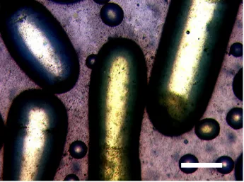
clay-armoured latex particles proved to be the most versatile solid stabilizers for a range of oils, including olive oil, n-hexadecane, styrene, and dicyclopentadiene and also gave Pickering emulsions with the longest stability as in the other cases some coalescence of droplets occurred, suggesting a larger coverage was achieved. More details on our Laponite-armoured latex particles can be found in the Chapter 4.
In order to create the non-spherical droplets, a stable Pickering emulsion must first be created by agitating a small oil phase with a large water phase in the presence of colloidally unstable particles. The particles will adhere to the created interface to produce very stable oil in water emulsions (stable for many weeks). This emulsion is then past through a thin capillary; typical lengths of 300 mm, with inlet and outlet diameters
of 686.0 μm and a minimum diameter at half-length of 273.0 μm. This
capillary is thinner than the created droplets, which forces them to elongate creating the needed extra interface. The particles were pushed through the capillary in a pulsating mode to maximize mixing and promote liquid-liquid interface assembly of the dispersed Pickering stabilizers. Average residence times of the droplets inside the capillaries were approximately 15 s.
(Figure 3). It should be stressed that no coalescence of droplets occurred inside the capillary. This was easily visually observed as the capillary used was transparent. The non-spherical shape was solely obtained by creating a jammed state of the adhered Pickering stabilizers upon droplet elongation induced by the confined capillary geometry.
The additional beauty of this method is that post-modification of these droplets, whilst maintaining their shape, can be carried out in ordinary weakly stirred reaction vessels. This provides an alternative to the manufacturing of non-spherical particles via droplet solidification carried out inside micro-fluidic channels.5,15-18
Figure 3:Light microscopic image of large non-spherical liquid droplets and small spherical droplets of styrene stabilized by Laponite clay armoured cross-linked
The second technique we shall show is that of interfacial buckling. The principle of buckling is to form a stable colloidosome with high surface coverage of particles and to remove part of the internal phase. Since the particles on the interface should be irreversibly adsorbed the size of the interface is locked. This means that as the total volume decreases, the colloidosome must change shape in order to accommodate this. We first observed this phenomena when we allowed a water droplet stabilised by polydisperse poly(divinylbenzene) evaporate in air:
Figure 4:The non-spherical structure (approx. 5 mm diameter) generated by the evaporation of a water droplet stabilised by DVB particles
Figure 5:Optical microscope image of 3 buckled colloidosomes (ca.50m dia.) consisting of an internal phase of toluene stabilised by crosslinked PMMA/DVB microgel particles
After these promising results it was decided to polymerise the droplets and attempt to vary the amounts of buckling observed. Toluene was replaced by styrene and AIBN as polymerisation initiator added. However FE-SEM analysis showed that no buckling occurred. It was postulated that perhaps there was not a high enough coverage of particles on the interface in the styrene water system to obtain a buckled system. It was decided to use Ludox TM-40 as a stabiliser using the same procedure as before, as it is known to give a high coverage in emulsion systems. Ludox TM-40 comes as a 40 wt% solution of ca. 25 nm silica spheres. Logically smaller droplets will be formed, since Ludox particles are an order of magnitude smaller than the microgel particles. 25 vol% of Ludox TM-40 was added to a 10 vol% mixture of styrene in water along with AIBN. The water was kept at pH 3.0 prior to ethanol addition.
Figure 6:FE-SEM image of PDEOS buckled colloidosome with clay armoured polystyrene latex particles as stabiliser.
The results were not reproducible as sometimes samples bubbled through for longer would be buckled less than those obtained after shorter times and only small amounts of buckling were observed before the emulsion became destabilised.
Figure 7: Figure depicting a microfluidic co-flow device generating monodisperse droplets.
Our group in collaboration with Kumacheva and co-workers recently showed an “inside-out” approach to monodisperse emulsion droplets stabilized by solid particles. Pickering droplets were post-polymerised via photo-initiation, and the preparation of non-spherical jammed structures was also demonstrated, in line with our previous results using glass capillaries.21 A disadvantage is that the production of these microfludic devices is complex and requires specialist equipment and a devoted clean laboratory. McQuade showed the production of a much simpler apparatus to generate monodisperse droplets using the same principle.22
Figure 8:schematic representation of a simpler microfluidic device.22
Liquid 1
For both systems the size of the droplets created are controlled by the size of the release aperture and by the apparent velocity of the droplet liquid. There is a limit to how small a droplet can be made with in a certain aperture. This is defined by the capillary number (Ca) which is calculated by multiplying the viscosity of liquid 1 by the apparent velocity of liquid 2 with respect to liquid 1 and dividing by the interfacial tension between the two liquids. This Ca number cannot be larger than 1 or a constant stream or jet will be produced instead of individual monodisperse droplets.
Kumacheva and Bon showed that for best results in microfluidic Pickering droplet formation the solid particles should be dispersed in the internal droplet phase, this allows rapid diffusion to the interface and means only a small excess of particles are required. This diffusion has been shown to be caused by hydrodynamic flow.23Moreover, it prevents fouling of the channels.
particles. This small amount of charge was added to give the resulting colloidosomes some electrostatic stabilisation against coalescence. Any created droplets had to be collected in a plastic dish, as droplets would break when coming in contact with glass, possibly because the methanol wets the glass much more than the plastic. Figure 9 shows monodispersed buckled droplets created using the simplified microfluidic device with a flow rate of 40 ml/min ofn-hexadecane (1/16” I.D. PTFE tube) and 2.5 ml/min (0.37 mm I.D. flat head syringe needle) of methanol containing 5 wt% of microspheres.
Conclusion
We have shown it is possible to change the shape of Pickering droplets via the post modification of a stable emulsion. They can either be elongated to give high aspect ratios or can be buckled to give a non-spherical structure with a higher surface area. This has only been done before on a drop-by-drop basis or via in-situ modification and scaffolding. Further work should be done in order to find how much force due to the buckling interface the particle can experience before the structure degrades. Also the maximum amount of buckling should be investigated when different wettabilities of particles are used.
Methodology
Apparatus