Abstract—This paper describes a novel signal processing method for extracting scratching time. Scratching motion is often monitored in various ways to evaluate an itching which appears as a symptom of various diseases. It is known that the altitude of skin diseases accompanied by itching is related to the length of the scratching time. Various studies have been developed to measure the scratching motion. And we have proposed the bed sensing system which is able to monitor heartbeat, respiration and body movement involved scratching motion while a patient is sleeping on the bed. In this paper, our proposed processing method, capable of extracting the scratching time, is applied to many kinds of measurement devices.
Index Terms—auto extraction, total scratching time, noninvasive bed monitoring, piezo-ceramics.
I. INTRODUCTION
TCHING can develop as a symptom of various diseases affecting patients, who scratch the itchy points to alleviate the itch [1]. However skin inflammation can become worse from the scratching [2]. In the case of skin diseases accompanied by itching, an evaluation of the itching is important; this aims at diagnosing the gravity of skin diseases and monitoring curative effect. There are various measurement sensors which are developed for this purpose [2]-[3]. In general, monitoring the scratching motions is used to evaluate the degree of the itching.
The scratching monitoring is based on the theorem that the gravity of skin diseases accompanied by itching is related to the length of the scratching time, and is effective in diagnosing skin diseases [4]-[5]. Because patients can control the scratching while they are awake, a more accurate evaluation would be made by monitoring the scratching motion while they are asleep.
Recently, various measurement sensors have been proposed as objective and quantitative systems. For example, they are aimed at recording the scratching motions, or the acceleration of wrist movement and its angular velocity. A strain gauge can be used
T. Shino is with the Graduate School of Hosei University, 3-7-2 Kajinocho Koganei-shi, Tokyo 184-8584, Japan.
*Y. Kurihara is with the Dept. of Computer and Information Science, Faculty of Science and Technology, Seikei University, 3-3-1 Kichijoji-kitamachi, Musashino-shi, Tokyo 180-8633, Japan (e-mail:
S. Nukaya is with the Division of Advanced Therapeutical Sciences Tokyo Medical and Dental University, 1-5-45 Yushima, Bunkyo-city, Tokyo 113-8510, Japan (e-mail: [email protected]).
K. Watanabe is with the System Control Engineering Department, Faculty of Engineering, Hosei University, 3-7-2 Kajinocho Koganei-shi, Tokyo 184-8584, Japan.
H. Tanaka is with the University Center for Information Medicine Tokyo Medical and Dental University, 1-5-45 Yushima, Bunkyo-city, Tokyo 113-8510, Japan.
to measure the expansion and contraction motions of fingers. An electromyograph can be used to measure the electrical activity of the muscles in the forearm. Other devices can be used to measure the change in the pressure on the back of the hand or the sound of the scratching [1]-[14]. We have proposed a noninvasive bed sensing device, using sets of piezo-ceramics under the bed feet, which is able to detect the heartbeats, respirations, body movement on the bed, and other biosignals [15]. The method for determining the scratching time, however, is bothersome, as the scorer has to look at the output wave shapes. This paper describes a novel signal processing method for extracting scratching time. We applied the proposed extracting process to the signals obtained from the scratching sensors: piezo-ceramics sensors, a strain gauge, an accelerometer, and a gyro sensor.
II. SCRATCHING MOTION AND PROBLEMS A. Characteristics of scratching motion and bed vibrations
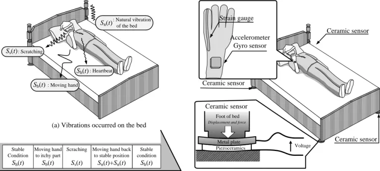
Fig. 1(a) shows the vibrations occurred on the bed and Fig.
1(b) shows scratching motions and their corresponding vibrations. When a subject is staying calmly, the hand of the subject is not moving, but the bed is vibrated by cyclical micro-vibration sh(t) produced by the heartbeat of the subject on the bed. When the subject feels itchy, s/he moves the arm forward to scratch the itching point. Then this arm motion causes vibration sb(t) whose cycle is long. The scratching motion oscillates the bed cyclically, and the vibration is larger than heartbeat. Since scratching is a reciprocating motion of the fingers, the sensor extracts the cyclically changing periods as scratching time in its data output. We call this vibration to be caused by scratch ss(t). The bed also vibrates due to the forces on the bed: natural vibration sv(t). When the scratching stops and the arm goes back, sb(t) occurs again. Since the natural vibration sv(t) could not stop immediately, two vibrations, sb(t) and sv(t), overlap. After these vibrations stop and the stable condition comes again, the bed is vibrated only by the micro-vibration sh(t) of heartbeat. In practice, though heartbeat vibration sh(t) never stops and does oscillate the bed, it is much smaller than the other vibrations. So, other than under the stable condition, the heartbeat vibration sh(t) could be disregarded. As described above, the subject’s hand motion and the bed vibrations during the scratching motion are characterized by the frequency and amplitude. Especially during the scratching, the signals are cyclical and larger in amplitude than the heartbeat signal. These characteristics indicate that if the scratching period Ts [s] could be detected out of the vibration ss(t), we are capable of determining the TST%, an index for evaluating the T. Shino, Y. Kurihara*, S. Nukaya, K. Watanabe, Member, IEEE, and H. Tanaka
Signal Processing Method for Extracting Scratching Time
I
itching. After obtaining the total scratching time Ts, we define the total measurement time Tm [s] and the number of scratching periods N, and the index of TST% is calculated as in eq. (1):
100
% 1
m N
i si
T T
TST (1)
B. Sensing Devices
Fig. 2 shows the conventional sensing devices, described as following:
Strain gauge measures degree of finger bending. It is fixed along the index finger. The register value of this gauge changes depending on the degree of finger bending. The measurement of this register value makes it possible to monitor the scratching motion. The register value of the gauge does not change unless the finger bends. This device measures the signals ss(k), sb(k) and sn(k) above.
An accelerometer and an angular velocity sensor are fixed onto the forearm. These measure the acceleration and angular velocity of the forearm respectively. The output of the accelerometer includes the gravitational acceleration. These devices measure the signals ss(k), sb(k), and sn(k) above.
Piezo-ceramics sensors are set under the legs of the bed and measure all the vibrations of the bed. This sensor is with a wide dynamic range and high sensitivity enabling the detection of micro-vibrations from the heartbeat by the change in acting force when a person is lying on the bed, and of vibration from body movement without saturation. This device measures the signals ss(k), sb(k), sh(k), sv(k), and sn(k) above.
C. Signal processing
The analogue outputs from these sensors are measured and converted into a digital signal named S(k) at a sampling time of dt. The variable k is defined as the digital time. If the output voltage S(k) is the linear sum of the each signal and high-frequency noise sn(k) as shown in Eq. (2).
S(k) = ss(k) + sb(k) + sh(k) + sv(k) + sn(k) (2) Fig. 3 shows the relation between the amplitude and the frequency contained in the vibrations ss(k), sb(k), sh(k), sv(k), and sn(k) respectively. According to the characteristics described above, in order to extract the scratching period Ts, we exerted the following steps. However, other sensors than the piezo-ceramics sensor could not measure the heartbeat vibration sh(k) or the natural vibration sv(k), so sh(k) =0 and there is no need to follow the step 1 for these sensors.
(Step 1)
In order to attenuate the natural vibration sv(k), moving average M(k) is calculated from Eq.(3). The value of q is degree.
k q
q k i
Si
k q
M 2 1
1 (3)
(Step 2)
The data for a certain period T are Discrete Fourier transformed from time domain to frequency domain. The frequency with the maximum spectrum during the period separates the transformed data into the lower-frequency periods and the other periods. The signal in the lower-frequency periods is sb(k) caused by arm motion and other body movements other than the scratching motion. The other periods contain the signals ss(k), sh(k) and sn(k). This process continues until the end
: Scratching
Ss(t)
: Moving hand
Sb(t)
: Heartbeat
Sh(t)
Moving hand to itchy part
Sb(t)
Stable Condition
Sh(t)
Scraching
Ss(t)
Moving hand back to stable position
Sn(t)+Sn(t)
Stable condition
Sh(t)
: Natural vibration of the bed
Sn(t)
(a) Vibrations occurred on the bed
(b) Scratching motions and each vibrations Fig. 1 Bed vibrations from scratching motion on bed
Ceramic sensor
Voltage Foot of bed
Displacement and force
Piezoceramics Metal plate
Ceramic sensor
Ceramic sensor Ceramic sensor Strain gauge
Accelerometer Gyro sensor
Fig. 2 sensing system
of data, with the beginning of each T delayed by an interval L from the previous T.
(Step 3)
The other periods which are interpreted as in Step 2 are divided into ss(k), sh(k) and sn(k) using each amplitude. If the signals for a certain period have larger amplitude than the average amplitude value of past sb(k), these periods are ss(k), which is scratching period. Otherwise, the signals are sh(k) or sn(k).
Through these three steps, the scratching time which mainly contains the scratching signal ss(k) can be extracted.
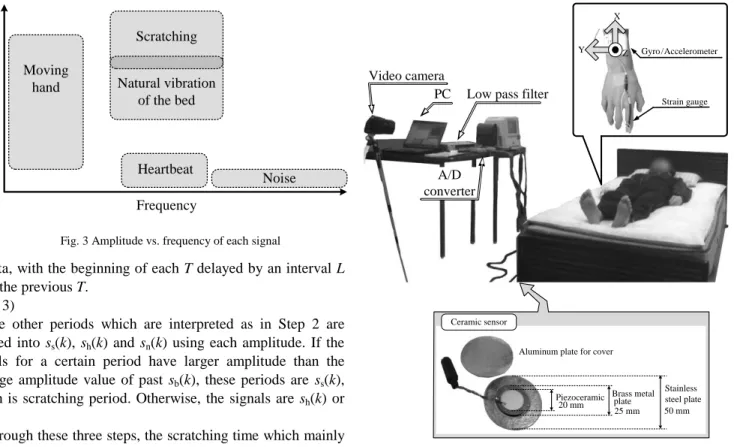
III. VALIDATION EXPERIMENTS A. Experimental System
Fig. 4 shows the experimental system. Strain gauge, accelerometer and gyro sensor are attached to the subject’s right hand, and piezo-ceramics sensors are set beneath the four each bed foot as shown in Fig. 4. It is known that the more distant the piezo-ceramics sensors are from the scratching point, the smaller their output signals are [16]. The subject in this experiment was male, approximately 170 cm in height and 50 kg in weight, and did not suffer from any sleep disorders. We explained to the subject in sufficient detail to give consent to the experiment.
B. Experimental Procedures
We set the sampling interval dt of each sensor as following:
the piezo-ceramics and the strain gauge to 1 ms, the gyro sensor to 2 ms, and the accelerometer sampling frequency to 204 Hz. In this experiment, we asked the subject to scratch the cheek, because patients with atopic dermatitis most frequently scratch the head area as a characteristic pattern [4]. The procedure of scratching is following:
As the starting position, the subject is lying on his back at the center of the bed with his arms and legs straight, as shown in Fig.
4. The subject scratched his right cheek 20 times using his right four fingers. He then returned his arm back to the starting position. After a 5-s pause, the subject once again scratched his cheek 20 times in a row. The set of scratching motions was repeated 35 times. The total scratching time for all 35 sets is
defined as Ts, and the ratio of TST% is calculated. The entire procedure described above was carried out using all the sensors.
While scratching, he pressed his fingers on the cheek moderately. The series of hand movements were performed smoothly. Sometimes he also turned over. In this experiment, we set N in Eq. (1) to 35 and q in Eq. (3) to 250. In step 2, T is set to 1 s, L to 0.5 s and the threshold frequency was the lowest one.
Regarding the accelerometer and the gyro sensor, Z-axis and Y-axis were monitored respectively, because these axes change most largely. Using the results, Ts and TST% are obtained from both the proposed and conventional extracting methods. The Ts defined from captured image is true value of Ts. The root mean square error (RMSE) [s] among the sensors were compared using as reference the Ts and TST% data obtained from the video camera images. The error rate is defined from the ratio of RMSE [s] to total measurement time Tm.
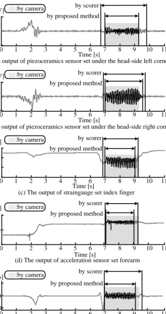
IV. RESULTS A. Measurement result
Fig. 5 shows an example of scratching periods decided from the captured images by reference camera, conventional method in which scorer look at wave shapes, and the proposed processing method. The gray areas mean the correct scratching period Ts defined by captured images. Fig. 5(a) and (b) show the results of piezo-ceramics sensors, (a) is set under the head side right corner and (b) is set under the head side left corner. The results of two piezo-ceramics sensors set under the foot side are the same as (a) and (b) respectively. Fig. 5(c) is the change of Frequency
Amplitude Moving hand
Scratching
Natural vibration of the bed
Heartbeat
Noise
Fig. 3 Amplitude vs. frequency of each signal
Gyro / Accelerometer
Strain gauge Y Z
X
Piezoceramic 20 mm
Brass metal plate
Stainless steel plate 50 mm Aluminum plate for cover
25 mm Ceramic sensor
Video camera
PC Low pass filter
A/D converter
Fig. 4 Experimental system
the strain gauge fixed along the index finger, (d) is that of the Z-axis element of the accelerometer set onto forearm, and (e) is that of the Y-axis element of the gyro sensor set on forearm. The conventional method needs the scorer to divide the signal of the scratching motion from that of the other signals, especially the turning over motion.
With (a) and (b), the subject stayed calm between 0 and 1 s.
At this time, piezo-ceramics sensor detected the heartbeat component of sh(t). When the subject turned from the left side of the bed to its center, between 1 and 3 s, the wave shape of the sensor (a) under the right side fluctuated to the positive in a long period. At the same time, the wave shape of (b) under the left side fluctuated slowly to the negative. This is because the center of the gravity of the subject on the bed shifted toward the left side. In the conventional method in which the scorer looks at the output wave shapes, the scorer was biased to misjudge that the signal was not from scratching but from other body movements.
From 3 to 6.5 s, when the subject was stationary again, these sensors detected the heartbeat component of sh(t). Between 6.5 and 7 s, when he moved his hand toward his right cheek, the output changed slowly. While he scratched, from 7 to 9.3 s, the output changes were cyclical and had large amplitudes, as described in the second chapter. After scratching till 10 s, while his arm moved back to the starting position, the output signal contained the natural vibration sv(k). After the moving of his hand, he stayed calm again. By the conventional extracting method, the scorer had also judged the natural vibration sv(k) as the scratching signal ss(k). Using the proposed processing method, the scratching signal ss(k) can be separated from the natural vibration sv(k), whose effect is attenuated.
Regarding the result (c), while staying calm between 0 and 1 s, 3 and 6.5 s, and 10 and 11 s, the subject’s finger did not move, so the output signals hardly changed. The strain gauge was not affected by the turning over movement. The median of the signal during the scratching motion was smaller than the other periods, not because of arm motion but of his finger bending to scratch. The changes of outputs during the scratching also were cyclical and had large amplitudes, as described in the second chapter. The proposed method, which applies the signal of strain gauge, is able to decide only the scratching time.
Regarding the result (d), the signal of the accelerometer hardly changed while the subject stayed calm; whereas the output fluctuated largely while he turned over on the bed. This is because the effect of gravitational acceleration changed with the change of sensor direction caused by the turning over motion.
Before and after the scratching, his arm motion generated low-frequency signals. During the scratching motion, the output signal also changed largely and cyclically as described in the second chapter. The proposed method, which applies the signal of accelerometer, is able to define only the scratching time.
The result (e) is similar to that of (d). While the subject stayed stationary, the signal hardly changed. When he turned over, the output signal changed slowly and largely. Before the scratching, the signal also changed slowly and largely along with the turning over movement. After the scratching, the signal changed
slowly but smaller than before the scratching. During the scratching motion, the output signal also changed largely and cyclically as described in the second chapter. The proposed method, which applies the signal of angular velocity, is able to define only the scratching time.
B. Evaluation
Table 1 shows the RMSE and the error rate of each sensor;
and table 2 shows the TST obtained from each sensor, the TST% and its error. The total measurement time Tm was 385 s and the correct total scratching time Ts was 179 s. By the conventional extracting method, in which the scorer looks at the output wave shapes, the wave shapes for the arm motion and for the scratching motion look similar regardless the type of the sensor used, making it difficult to divide the time frames. The Ts therefore included the time for moving the arm, resulted in enlarged TST%. The RMSE of the four piezo-ceramics sensors was less than 1 s, and the maximum error rate was 0.24 %.
-200 0 200
-200 0 200
1 2 3 4
-2 0 2
-500 0 500
0 1 2 3 4 5 6 7 8 9 10 11
0 1 2 3 4 5 6 7 8 9 10 11
0 1 2 3 4 5 6 7 8 9 10 11
0 1 2 3 4 5 6 7 8 9 10 11
0 1 2 3 4 5 6 7 8 9 10 11
OutputOutputOutputAccelerationAngular Velocity by proposed method
Time [s]
(a) The output of piezoceramics sensor set under the head-side left corner
(b) The output of piezoceramics sensor set under the head-side right corner
(c) The output of straingauge set index finger Time [s]
Time [s]
Time [s]
Time [s]
(d) The output of acceleration sensor set forearm
(e) The output of angular velocity sensor set forearm
[deg/s] by scorer
[mV]
[mV]
[V]
[G]
by proposed method by scorer by proposed method by scorer by proposed method by scorer by proposed method
by scorer :by camera
:by camera
:by camera
:by camera :by camera
Fig. 5 Results of the scratching and turning over motion
Regarding the ceramics sensors set under the foot side, the RMSEs of the proposed extracting method became smaller than those of the conventional method. The errors of TST% obtained from the proposed method became smaller than those of the conventional method. With the sensor set under the foot side right, the TST from the conventional method was long, while that from the proposed method was short.
Both RMSEs from the strain gauge set along the subject’s index finger were less than 0.6 s; both error rates were approximately 0.1 %. The TST from the conventional method was longer than that from the proposed method, which in turn was shorter than correct TST.
With the Ts of acceleration, the error rates obtained from both methods were about 0.2 %. The TST% calculated from both methods were at the same level.
Regarding the angular velocity, the RMSE from the proposed method was longer than the correct time by 0.2 s, and the error rates calculated from both methods were approximately 0.1 %.
The TST of the proposed method was shorter than that of the conventional extracting method.
V. DISCUSSION
The errors calculated with the proposed signal processing method and with the conventional method with a scorer’s observation are at the same level. The proposed extraction method can separate the scratching motion from the other motions, thus making it operational without the judgment as to whether a signal is caused by a scratching motion, whereas this judgment is needed for the conventional method. With the conventional method, the main reason for the Ts error is the difficulty to separate the scratching motion from other motions before and after the scratching. With the proposed extracting method, the Ts error depends on how long the period T is set in Step 2, or how to compare the amplitudes in Step 3. Step 2 is the process which separates the low frequency signal sb(k) out of the data obtained for a certain period, using its peak frequency with the data acquisition delay by an interval of L. In this step, the beginning and the end of Ts, required elements to calculate
TST%, depend on the period T and the interval L. Therefore, a shorter interval enhances the resolution and accuracy of Ts. In this experiment, the reason why the TST of the acceleration and of the angular velocity were judged in a shorter period also lies in the interval L. Step 3 is the process to compare the amplitudes of sh(k), sn(k), and ss(k) with the average value of past amplitude of low frequency signal sb(k). However the changes in the low frequency signal sb(k) were different from each other; the Step 3 could be improved to be adapted to each sensor.
VI. CONCLUSION
In this paper, we proposed the signal processing method for extracting the scratching time, and applied the method to the piezo-ceramics sensors, the strain gauge, the accelerometer, and the angular velocity sensor as conventional sensors to monitor the scratching motions. The base of this algorism is the characteristics that scratching motion generates cyclic larger-amplitude vibration and signals. This processing is able to calculate the TST%, which is the index of scratching evaluation, and its accuracy is the same as the conventional extracting method in which a doctor looks at the recoded wave shapes to decide the scratching time. In the case of using infrared video camera, calculating the TST% requires significant time, about the same as the measurement time. The proposed extracting method enables to extremely shorten the time to calculate the TST%. In summary, the proposed method can shorten the calculation time of Ts and keep the accuracy of extracting the scratching time. Shortened the calculating time could relieve the doctor of some burden and increase the time to care the patients. The proposed method can also be applied to the electronic medical recording, and there is no fluctuation due to the scratching time judgment, because it is digitally processed.
Our future works are the optimization of Step 2 of the certain time T for Fourier transferring and interval L for the determination of the TST resolution, and the development of comparison way for Step 3.
TABLEI RMSE AND THE ERROR RATE
Sensors Method RMSE [s] Error rate Piezo-ceramics,
head side left
Conventional 0.40 0.10
Proposed 0.68 0.18
Piezo-ceramics, head side right
Conventional 0.64 0.17
Proposed 0.74 0.19
Piezo-ceramics, foot side left
Conventional 0.92 0.24
Proposed 0.73 0.19
Piezo-ceramics, foot side right
Conventional 0.94 0.24
Proposed 0.79 0.20
Strain gauge Conventional 0.37 0.10
Proposed 0.53 0.14
Accelaration Z-axis
Conventional 0.64 0.17
Proposed 0.83 0.22
Angular velocity Y-axis
Conventional 0.31 0.08
Proposed 0.54 0.14
TABLEII TST,TST% AND THE ERRORS
Sensors Method TST [s] TST% Error [%]
Camera Conventional 179.31 46.57 -
Proposed - - -
Piezo-ceramics, head side left
Conventional 176.12 45.75 0.82 Proposed 168.50 43.77 2.81 Piezo-ceramics,
head side right
Conventional 186.17 48.36 -1.79 Proposed 184.50 47.92 -1.35 Piezo-ceramics,
foot side left
Conventional 204.36 53.08 -6.51 Proposed 187.50 48.70 -2.13 Piezo-ceramics,
foot side right
Conventional 201.51 52.34 -5.77 Proposed 163.50 42.47 4.11 Strain gauge Conventional 185.24 48.11 -1.54 Proposed 174.00 45.19 1.38 Accelaration
Z-axis
Conventional 162.62 42.24 4.33 Proposed 160.00 41.56 5.02 Angular velocity
Y-axis
Conventional 177.78 46.18 0.39 Proposed 169.00 43.90 2.68
ACKNOWLEDGEMENT
This work was supported by a Grant-in-Aid for Scientific Research (23760372).
REFERENCES
[1] Y. Ishibashi, K. Yoshikawa, “The skin diseases with strong itch, the manual for discernment and therapeutics,” 1991.
[2] R. Miyaji, A. Ikoma, “Forefront of medical dermatologists series:
Frontiers itching,” 2006.
[3] R. Miyaji, “Q&A Itching,” 2007.
[4] T. Ebata, H. Aizawa, R. Kamide, M.Niimura, “The Characteristics of nocturnal scratching in adults with atopic dermatitis,” British Journal of Dermatology Vol. 141, pp. 82-86, 1999.
[5] H. Izumi, T. Ebata, Y. Sato, H. Aizawa, R. Kamide, M. Niimura, “A Simplified Method for the Measurement of Nocturnal Scratching with an Infrared Video Camera,” The Skin Vol. 39, pp. 560-563, 1997.
[6] J. A. Savin, W. D. Paterson, I. Oswald, “SCRATCHING DURING SLEEP,” The Lancet Vol. August 11, pp. 296-297, 1973.
[7] T. Ebata, et al., “Use of a wrist activity monitor for the measurement of nocturnal scratching in patients with atopic dermatitis”, British Journal of Dermatology Vol. 144, pp.305-309, 2001.
[8] H. Yokoi, Y. Noro, K. Umeda, H. Mizutani, “Detection of Human Scratching Behavior during Sleep with Acceleration sensor,” Tokai of society related to electricity branch union rally O-323, 2008.
[9] N. V. Bergasa, D. W. Alling, T. L. Talbot, et al., “Effects of Naloxone Infusions in Patients with the Pruritus of Cholestasis,” Annals of Internal Medicin Vol. 123, No. 3, pp. 161-167, 1995.
[10] Y. Kawabe. K. Aritake, Y. Noro, K. Umeda, H. Mizutani, “A Study of sensor for Detection of Human Scratching Behavior during Sleep,” Tokai of society related to electricity branch union rally O-329, 2007.
[11] M. Konishi, K. Aritake, Y. Noro, K. Umeda, H. Mizutani, “A Study of sensor for Detection of Human Scratching Behavior during Sleep,” Tokai of society related to electricity branch union rally O-322, 2008.
[12] T. Aoki, H. Kushimoto, Y. Hishikawa, J. A. Savin, “Nocturnal scratching and its relationship to the disturbed sleep of itchy subject,” Clinical and Experiment Dermatology Vol. 16, pp. 268-272, 1991.
[13] J. R. Burch, P. V. Harrison, “THE MEASUREMENT OF ITCH,”
Measurements we Couldn't Make Without a Micro, pp. 9-12, 1988.
[14] K. Endo, H, Sumitsuji, T. Fukuzumi, J. Adachi, T. Aoki, “Evaluation of Scratch Movements by a New Scrath-Monitor to Analyze Nocturnal Itching in Atopic Dermatitis,” Acta Derm Venereol (Stockh) Vol. 77, pp.
432-435, 1997.
[15] S. Nukaya, T. Shino, Y. Kurihara, K. Watanabe, H. Tanaka,
“Noninvasive Bed Sensing of Human Biosignals via Piezoceramic Devices Sandwiched Between the Floor and Bed,” Sensors Journal Early Access (http://ieeexplore.ieee.org/xpl/tocresult.jsp?isnumber=4427201).
[16] T. Shino, Y. Kurihara, S. Nukaya, K. Watanabe, H. Tanaka,
“Unconstrained Bed Monitoring System for Scratching Motion,”
proceedings 24th International Conference on Computers and Their Application in Industry and Engineering, pp. 135-140, 2011.