http://wrap.warwick.ac.uk
Original citation:
Huang, Tian, Liu, Songtao, Mei, Jiangping and Chetwynd, D. G.. (2013) Optimal design
of a 2-DOF pick-and-place parallel robot using dynamic performance indices and
angular constraints. Mechanism and Machine Theory, Volume 70 . pp. 246-253.
Permanent WRAP url:
http://wrap.warwick.ac.uk/58651
Copyright and reuse:
The Warwick Research Archive Portal (WRAP) makes this work by researchers of the
University of Warwick available open access under the following conditions. Copyright ©
and all moral rights to the version of the paper presented here belong to the individual
author(s) and/or other copyright owners. To the extent reasonable and practicable the
material made available in WRAP has been checked for eligibility before being made
available.
Copies of full items can be used for personal research or study, educational, or
not-for-profit purposes without prior permission or charge. Provided that the authors, title and
full bibliographic details are credited, a hyperlink and/or URL is given for the original
metadata page and the content is not changed in any way.
Publisher’s statement:
© 201
3
, Elsevier. Licensed under the Creative Commons
Attribution-NonCommercial-NoDerivatives 4.0 International
http://creativecommons.org/licenses/by-nc-nd/4.0/
A note on versions:
The version presented here may differ from the published version or, version of record, if
you wish to cite this item you are advised to consult the publisher’s version. Please see
the ‘permanent WRAP url’ above for details on accessing the published version and note
that access may require a subscription.
Optimal Design of a 2-DOF Pick-and-place Parallel
Robot using Dynamic Performance Indices and
Angular Constraints
Tian Huang
a,b*, Songtao Liu
a, Jiangping Mei
a, and Derek G. Chetwynd
ba Key Laboratory of Mechanism Theory and Equipment Design of State Ministry of Education, Tianjin University, Tianjin 300072, China b School of Engineering, The University of Warwick, Coventry CV4 7AL, UK
Abstract
This paper presents an approach for the optimal design of a 2-DOF translational pick-and-place parallel robot. By taking account of the normalized inertial and centrifugal/Coriolis torques of a single actuated joint, two global dynamic performance indices are proposed for minimization. The pressure angles within a limb and between two limbs are considered as the kinematic constraints to prevent direct and indirect singularities. These considerations together form a multi-objective optimization problem that can then be solved by the modified goal attainment method. A numerical example is discussed. A number of robots designed by this approach have been integrated into production lines for carton packing in the pharmaceutical industry.
Keywords: Parallel robot; Optimal design
1. Introduction
Parallel robots created using the properties of parallelograms and actuated by the proximal revolute joints draw continuing interest from academia and industry. This is exemplified by the well-known Delta robot [1], including many very successful applications in the food and pharmaceutical industries of modified versions of its concept, such as the 2-DOF translational robot named Diamond [2] and also by, for example, the 4-DOF SCARA-type Adept Quattro robot [3].
Optimal design is an important issue in the development of Delta-like parallel robots. Once a task workspace prescribed as either a rectangle in 2D or a cylinder in 3D space of given size, this problem is primarily concerned with the determination of a set of dimensional parameters by optimizing one or more cost functions based on either kinematic or rigid body dynamic performance indices expressed in a global sense. Conventionally, the global kinematic performance indices can be represented by the mean value [4] and standard deviation [5,6] of algebraic characteristics of the Jacobian throughout the entire workspace, for example, its condition number, minimum singular value and determinate. Some of these have been widely accepted and extended into various modified versions to deal with the kinematic dimensional synthesis problem of 2-4 DOF Delta-like parallel robots [7–13]. However, merely optimizing the kinematic performance indices is not adequate because the inertial and centrifugal/Coriolis effects must be taken into account when such a robot runs at very high-speed and high-acceleration. The performance indices for rigid body dynamics [14–18] must then be considered. Little has so far been reported on this aspect of the design of high-speed pick-and-place parallel robots [19].
Drawing on our previous work [5,6,19,20,21], this paper deals with the optimal design problem of the Diamond robot (see Fig. 1). It particularly emphasizes: (i) the formulation of dynamically relevant, meaningful performance indices that simultaneously account for the inertial and centrifugal/Coriolis effects; and (ii) the generation of a set of kinematic constraints in an easy to visualize manner to prevent the occurrence of direct and indirect singularities. Given the task workspace, the influences of kinematic constraints on feasible domains of the design variables are investigated via an in-depth discussion, prior to the solution of a multi-objective optimization problem. Finally, the servomotor and gear reducer parameters are specified using a standardized pick-and-place motion cycle.
2. Kinematic and Dynamic Analyses
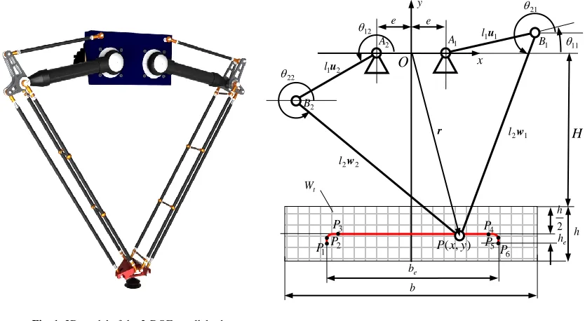
Fig. 1 shows a 3D model of the 2-DOF parallel robot under consideration. The robot is composed of a base, a movable platform and two identical kinematic chains. Driven independently by two active proximal links, the robot provides a movable platform with a 2-DOF translational motion capability. For more information about detailed mechanical design of the robot
design using dynamic performance indices and angular constraints.
Note that the motions of the active and passive proximal links are identical, as are those of the distal links within the parallelograms, allowing the kinematic model of the robot to be simplified to the 5R planar linkage shown in Fig. 2. In the
xy
O coordinate system, the position vector,r
x y
T, of the pointPcan be written asi
i l
l e
i x u w
rsgn() ˆ1 2 , i1,2 (1)
T1
1 sin
cos i i
i
u ,wi
cos2i sin2i
T
T0 1 ˆ x , 2 1 1 1 ) sgn( i i i
where l1, l2, ui and wi are the lengths and unit vectors of the proximal and distal links; e is the offset between O and
i
A; 1i and 2i are the position angles of the proximal and distal links, respectively. Inverse positional analysis gives
i i i i i i i F G F G E i E 2 2 2 1 ) sgn( arctan 2
(2)
y l
Ei21 , Fi2l1(xsgn(i)e), Gi x y e l l 2sgn(i)ex
2 2 2 1 2 2
2
Thus, ui is determined and then from Eq.(1)
sgn(i)eˆ l1 i
l2i r x u
w (3)
Taking the first and second time derivatives of Eq.(1) leads to the inverse velocity and acceleration models [20]
Jv
θ1 , ( )
1 Ja f v
θ (4)
x
J J J 1
, Jx
w1 w2
T, J l
wiQui
T 1diag
T12 11 1
θ , v
x y
T, 0 1 1 0 Q ,
13 T T 2 1 T T 1 T ) ( l l l l i i i i i i i i i v Qu w u u w w u w v v f
, i1,2
T12 11 1
[image:3.612.100.517.88.317.2]θ , a
x y
T where JandJxare the direct and indirect Jacobians.Fig. 1. 3D model of the 2-DOF parallel robot Fig. 2. Schematic diagram of the robot x y
O
e 1 1u l ) , (x y P r 2 1u l 1 A 2A B1
2 B 2 2w l e b h t W 2 h e h e b 1 2w l 11 21 12 22 1
[image:3.612.42.573.411.721.2]According to the assumptions addressed in [20], the driving toques imposed upon the proximal links can be formulated by
a v g
τ τ τ τ
(5)
T2 1
τ , τa
mJ IAJ
aT ,
v IA
τ f ,
T T11 12 ˆ
cos cos
g m r gA A mg
τ J y
T T
1 1 1 2 2 2 1
1
T 2 1
l
Qw Qu w w Qu w J
w Qw ,
T ˆ 0 1
y
whereτ,τa,τvand τgare the actuated, inertial, centrifugal/ Coriolis and gravitational torques; m is the equivalent mass of the
moving platform; IAis the equivalent moment of inertia of the active proximal link about its axis of rotation; m rA A is the mass-radius product of the active proximal link assembly. The detailed contributors to the inertial parameters are given in Table 1.
3. Optimal design
As shown in Fig. 2, let the task workspace, denoted byWt, of the 2-DOF robot be a rectangle of widthband height h, withH
the distance from thexaxis to the upper bound of Wt. Given values for the mass per unit length of the proximal and distal links and for the equivalent mass of the platform, the optimal design of the robot becomes a determination of the dimensional parameterse, l1, l2andHthrough optimizing global dynamic performance indices subject to a set of appropriate geometrical constraints. These design constraints and cost functions for the minimization are formulated below.
3.1. Constraints
3.1.1 Geometrical Constraints
Room must be made available for situating two servomotors on the base, which affects the offset e [5]. The first geometrical constraint is therefore that
min
e e≥ (6)
Also, for pick-and-place robots actuated by proximal revolute joints, an equality constraint can be set as
1
2
b e l (7)
In addition, the constraints to allow the mechanism to be assembled must be considered, namely
2
22 1
/ 2 0
Hh b e l l , l2 l1 H0 (8)
3.1.2 Kinematic Constraints
Kinematic constraints are needed to prevent the occurrence of direct and indirect singularities throughout the entire workspace. They can be expressed in easily visualized geometrical terms by examining the determinants of the direct and inverse Jacobians given in Eq.(4)
Table 1
Inertial parameters of the simplified rigid body dynamics model
Moment of Inertia Lumped Mass
2 2 2
proximal distal 1 / 2 bracket 1 gear
A
I I m l m l n I mmplatformmdistal
n— gear ratio; Igear— moment of inertia of the gear reducer; Iproximal— moment of inertia of the
proximal link about its axis of rotation; mplatform, mbracket,mdistal— masses of the platform, bracket and
distal link;m rA Amproximal proximalr mbracketmdistal/ 2l1 — the mass-radius product of the active
1 1
det( ) i i
i l
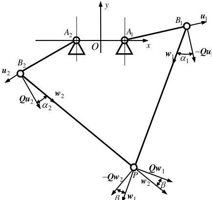
J w Qu , det(Jx)w Qw2 1 (9)
Thus, two angular constraints can be defined, see Fig. 3.
a) The Angular Constraint within a Limb
t
max
1,2 max max i
W i
r ,
T
arccos
i i i
w Qu (10)
where i is the acute angle between the velocity (along Qui) of point Bi and the component of force alongwi transmitted from the proximal link to the distal link, so representing the force/motion transmission capability within a limb. Note that the direct singularity occurs at i 90 when det(J)0. The maximum value of
1,2 max i
i throughout Wt must be bounded by a specified allowable value
.b) The Angular Constraint between Two Limbs
tmax max
W
r ,
T 2 1
arccos
w Qw (11)
where is the acute angle between the velocity (along Qw1 (Qw2)) of the point P and the force (along w1 (w2)) imposed by the distal link in limb 2(1) at the same point. It represents the force/motion transmission capability from limb 2(1) to limb 1(2) under the condition that the actuated joint in limb 1(2) is locked. Again, note that the indirect singularity occurs at
90
, for which det(Jx)0. The maximum value of throughout Wt must be less than an allowable value
.Wide experience with planar linkage recommends that
and
should be set in the range 40 50 to ensure good kinematic performance of the robot.3.2. Global Dynamic Performance Indices
The robot usually runs at high speed and high acceleration, so τ is dominated primarily by τaandτv. Hence, the following global dynamic performance indices are proposed.
Firstly, the component of τa associated with the actuated joint in the thi limb is expressed
, 1
A
a i i
I l
G a, i1, 2 (12)
[image:5.612.196.413.108.313.2]where
Fig. 3. Pressure angles within a limb and between two limbs x
y
O
1
u
P
2
u
1
A
2
A
1
B
2
B
2
w
1 w 2
2
Qu
1 Qw
2
w
1
Qu
1 w
1
2
Qw
T T
1 2 1
1
1
T T
2 1 2
2 2 cos cos cos cos cos cos
w Q w
G
w Q w
G , 2 1 A ml I
The maximum value of the normalized l1a i, IA necessary to generate a 1 at a specific configuration can be expressed explicitly as
2 T
max, 2
cos 1
( ) 2
cos cos
i
a i i i i
i
G G G (13)
Clearly, both the direct singularity, i.e. i 90 , and the indirect singularity, i.e. 90 , lead to amax,i
Gi . Therefore,the maximum value of
max,
1,2max a i i
i G throughout Wt can be used as one of the global performance indices for
minimization:
t max, 1,2= max max min
aG a i i
W i
r G (14)
Secondly, the component of τv associated with the actuated joint in the thi limb has the form
T
, 2
1
A
v i i
I l
v H v,
T T 1 T
2 3 T
i i i i i i
i i i l l
w u w w u u
H
w Qu
(15)
The maximum value of the normalized 2 1 v i, A
l I needed to generate v 1 at a specific configuration can be characterized by
the maximum singular value of Hi, i.e. vmax,i(Hi). Again, the direct singularity, i.e. i 90 , leads to vmax,i(Hi) .
Thus, the maximum of max, 1,2
max v i( i)
i
H throughout Wt can be used as another global performance index for minimization:
t
max, 1,2
max max min
vG v i i
W i
r H (16)
With the two cost functions given in Eq.(14) and Eq.(16) to hand, a weighted sum can be used to generate a compromise between the inconsistent optimized dimensions achieved by minimizing each of aG and vG independently. So,
T min
G G
w τ (17)
where τG
aG vG
T and wG
waG wvG
T is a vector of weighting coefficients. In order to avoid arbitrary design opinionswhen selecting these weights, a multi-objective optimization problem is solved by the goal attainment method [22]. It can be formulated in brief as
min
(18) subject to
*
G G G
τ w τ , *
min min
TG aG vG
τ , *
G G
w τ
max 0
, max
0
2
22 1
/ 2 0
Hh b e l l , l2 l1 H 0
1
2 0
b e l , e min e 0
4. Example
gear reducer of ratio n20 having a moment of inertia of 4 2
gear 0.47 10 kg.m
I to match with high-speed servomotors of low inertia and moderate capacity. The cross sections and materials of the proximal and distal links are taken to be similar to those used in the existing Delta robot. The inertial parameters (fixed or functions of link lengths) are then as given in Table 2. The problem can be solved directly by, e.g., the Matlab® Optimization Toolbox, but a monotonical analysis is more helpful for
gaining deep insights into the influences of the kinematic constraints on the feasible domains of the design variables. So, Fig. 4 (a)-(c) show how, for three plausible values of e at 0.025 m increments, aG and vG are influenced by l2 and H, taking into account only the geometrical constraints given in Eq.(8).
Both aG and vG decrease with the decrease of e. Hence, using a relatively small value of e helps to improve the rigid
body dynamic performance under the geometrical constraints eemin and l1b/ 2e. It is observed that H can be modeled as a linear function of l2 along the valleys of aG andvG. Also, along the corresponding valley lines, increasing l2 leavesvG almost unchanged whereas aG decreases. Again, taking 0.025 m steps in e and l1, Fig. 5(a)-(c) plot two straight lines
representing the projections of the valleys of aG and vG into the l2H plane onto contours bounded by sets of
and [image:7.612.86.522.300.370.2]
. The feasible domains of l2 and H are seen to increase as e decreases for a specific combination of
and
.Table 2
Equivalent moments of inertia and masses Moment of
Inertia Value or Expression (kg m )
2 Mass Value or Expression (kg)
gear
I 4
0.47 10 mplatfotm 0.8
proxmal
I 2
1 1
0.3126l 0.05768l0.00705 mdistal 0.45l20.3835 braket
m 0.545
gear ratio:n20 :1; mass radius product of the proximal link: 2
proximal proximal 0.461 0.32291 0.0229
m r l l (kg m) .
0.8 1 0.5 0.6 0.7 0.8 1 2 3 4 0.8 1 0.5 0.6 0.7 0.8 1 2 3 4
Fig. 4. Variations of and vs. and : (a) , ; (b) , ; and (c) ,
(m)
H l2 (m) H (m) l2 (m)
aG vG aG vG (b) (c) 0.8 1 0.5 0.6 0.7 0.8 1 2 3 4 aG vG (a) (m)
H l2 (m)
[image:7.612.70.548.412.534.2]0.6 0.7 0.8 0.9 1 1.1 1.2 0.5 0.55 0.6 0.65 0.7 0.75 0.8 0.85 0.9
Fig. 5. Optimized and subject to the angular constraints: (a) , ; (b) , ; and (c) ,
(m) H
2 (m) l 42 40 38 36 H
2 l 42 46 50 aG vG 54 (c)
0.6 0.7 0.8 0.9 1 1.1 1.2 0.5 0.55 0.6 0.65 0.7 0.75 0.8 0.85 0.9 (m) H
2 (m) l 42 40 38 36 H
2 l aG vG 54 50 46 42 (b)
0.6 0.7 0.8 0.9 1 1.1 1.2 0.5 0.55 0.6 0.65 0.7 0.75 0.8 0.85 0.9 (m) H
[image:7.612.65.545.571.711.2]Thus, taking a relatively small value of e also helps to improve the force/motion transmission capabilities provided that
min
ee and l1b/ 2e are satisfied. Furthermore, for a givene, l2 (H) needs to take a relatively large value to satisfy a
stricter constraint on
whereas a relatively smaller value is wanted to meet a stricter constraint on
. Thus, selecting
50 ,
40 and a set of emin, as discussed, with l1b 2emin, the corresponding optimized * 2l and *
H can be
obtained by solving the multi-objective optimization problem given in Eq.(18). The results are given in Table 3 and the optimal points identified in Fig. 5. In practice, we take a set of dimensions associated with emin0.125 m as the final design.
With the dimensional parameters determined, specifications for the servomotor rotational speed, torque, power and moment of inertia can be estimated using the Extended Adept Cycle [3] as shown in Fig. 2 with be0.7 m and he0.025 m. By
utilizing the 3-4-5 polynomial as the motion rule along the horizontal and vertical directions, we assume that, without considering the payload, the maximum accelerations along them are amax,x 150 m/s2 and
2
max,y 75 m/s
a . Then, the maximum rotational speed, the maximum and rated torque and power of the servomotor can be achieved by the formulae given in [21]. Consequently, we may choose a servomotor with small inertia and medium capacity with the gear reducer given in Table 2. Allowing for a transmission efficiency of 90%, these considerations lead to the motor specifications shown in Table 4.
The proposed approach has been transferred successfully to a robot manufacturer to design and develop real products and a number of production lines have been built for carton packing in the pharmaceutical industry. A speed of 80 ppm can be achieved reliably for simultaneously packing three non-PVC transfusion bags having a total mass of 1.5 kg, as depicted in Fig. 6.
5. Conclusions
This paper considers a methodology for the optimal design of a 2-DOF translational parallel robot intended for high-speed pick-and-place operations. The conclusions are drawn as follows:
(1)We have defined two global kinematic constraints using the pressure angles within one limb and between the two limbs. These readily visualized constraints are used to ensure the force/motion transmission capabilities of the system throughout the entire workspace by preventing direct and indirect singularities.
(2)We have proposed two comprehensive global dynamic performance indices by simultaneously taking into account the inertial and centrifugal/Coriolis torques of a single actuated joint. These indices are used to formulate a weighted cost function for minimization to ensure the rigid body dynamic performance of the system throughout the entire workspace.
(3)We have established a feasible solution framework for optimal design of the robot under consideration by formulating and solving a multi-objective optimization problem using the modified goal attainment method.
Acknowledgment
This research is partially supported by the National Natural Foundation of China (NSFC) under grant 51135008.
Table 4
Specifications of the selected servomotor
Rated power (kw) 1.5 Moment of inertia (kg.m2) 3.17 10 4
Max. rotational speed (rpm) 5000 Rated toque (N.m) 4.77
[image:8.612.112.505.300.522.2]Rated rotational speed (rpm) 3000 Max. toque (N.m) 14.3
References
[1] R. Clavel, Delta, a fast robot with parallel geometry, 18th International Symposium on Industrial Robots, Sydney, Australia, 1988, 91–100. [2] T. Huang, M. Li, Z.X. Li, A 2-DOF translational parallel robot with revolute joints, CN patent 1355087, Dec. 31, 2001.
[3] F. Pierrot, V. Nabat, S. Krut, P. Poignet, Optimal design of a 4-DOF parallel manipulator: from academia to industry, IEEE Transactions on Robotics 25(2) (2009) 213–224.
[4] C. M. Gosselin, J. Angeles, A globe performance index for the kinematic optimization of robotic manipulators, ASME Journal of Mechanical Design 113(3) (1991) 220–226.
[5] T. Huang, Z. X. Li, M. Li, D. G. Chetwynd, C. M. Gosselin, Conceptual design and dimensional synthesis of a novel 2-DOF translational parallel robot for pick-and-place operations, ASME Journal of Mechanical Design 126(3) (2004) 449–455.
[6] T. Huang, M. Li, Z. X. Li, D. G. Chetwynd, D. J. Whitehouse, Optimal kinematic design of 2-DOF parallel manipulators with well-shaped workspace bounded by a specified conditioning index, IEEE Trans. on Robotics and Automation 20(3) (2004) 538–543.
[7] K. Miller, Optimal design and modeling of spatial parallel manipulators, International Journal of Robotics Research 23(2) (2004) 127–140.
[8] M. Stock, K. Miller, Optimal kinematic design of spatial parallel manipulators: application to linear delta robot, ASME Journal of Mechanical Design 125(2) (2004) 292–301.
[9] V. Nabat, M. O. Rodriguez, O. Company, S. Krut, F. Pierrot, Par4: very high speed parallel robot for pick-and-place, Proceedings of the IEEE/RSJ International Conference on Intelligent Robots and Systems, Alberta, Canada, 2005, 1202–1207.
[10] X. J. Liu, J. S. Wang, A new methodology for optimal kinematic design of parallel mechanisms, Mechanism and Machine Theory 42(9) (2007) 1210–1224. [11] X. J. Liu, Q.M. Wang, J. S. Wang, Kinematics, dynamics and dimensional synthesis of a novel 2-DOF translational manipulator, Journal of Intelligent and
Robotic Systems 41 (2004) 205–224.
[12] M. A. Laribia, L. Romdhanea, S. Zeghloulb, Analysis and dimensional synthesis of the DELTA robot for a prescribed workspace, Mechanism and Machine Theory 42(7) (2007) 859–870.
[13] H. B. Choi, A. Konno, M. Uchiyama, Design, implementation, and performance evaluation of a 4-DOF parallel robot, Robotica 28(1) (2010) 107–118. [14] T. Yoshikawa, Dynamic manipulability of robot manipulators, Proceedings of the IEEE International Conference on Robotics and Automation, Kyoto,
Japan, 1985, 1033-1038.
[15] O. Ma, J. Angeles, The concept of dynamic isotropy and its applications to inverse kinematics and trajectory planning, Proceedings of the IEEE International Conference on Robotics and Automation, Cincinnati, OH, 1990, 481–486.
[16] H. Asada, Dynamic analysis and design of robot manipulators using inertia ellipsoids, Proceedings of the IEEE International Conference on Robotics and Automation, Atlanta, 1984, 94–102.
[17] S. Tadokoro, I. Kimura, T. Takamori, A measure for evaluation of dynamic dexterity based on a stochastic interpretation of manipulator motion, Proceedings of the IEEE International Conference on Robotics and Automation, Pisa, Italy, 1991, 509–514.
[18] O. Ma, J. Angeles, Optimum design of manipulators under dynamic isotropy conditions, Proceedings of the IEEE International Conference on Robotics and Automation, Atlanta, GA, 1993, 470–475.
[19] L. M. Zhang, J. P. Mei, X. M. Zhao, T. Huang, Dimensional synthesis of the delta robot using transmission angle constraints, Robotica, 30 (2012) 343-349. [20] T. Huang, J. P. Mei, Z. X. Li, X. M. Zhao, D. G. Chetwynd, A method for estimating servomotor parameters of a parallel robot for rapid pick-and-place
operations, ASME Journal of Mechanical Design 127(4) (2005) 596–601.
[21] S. T. Liu, T. Huang, J. P. Mei, X. M. Zhao, P. F. Wang, D. G. Chetwynd, Optimal design of a 4-DOF SCARA type parallel robot using dynamic performance indices and angular constraints, ASME Journal of Mechanisms and Robotics 4(3) ( 2012) 031005-1–031005-10.
Listing of figure captions:
Fig. 1. 3D model of the 2-DOF parallel robot
Fig. 2. Schematic diagram of the robot
Fig. 3. Pressure angles within a limb and between two limbs
Fig. 4. Variations of and vs. and : (a) , ; (b) , ; and (c) ,
Fig. 5. Optimized and subject to the angular constraints: (a) , ; (b) , ; and (c) ,