http://wrap.warwick.ac.uk
Original citation:
Birrell, Stewart A., Wilson, Daniel J, Yang, C. P., Dhadyalla, Gunwant and Jennings,
Paul A.. (2015) How driver behaviour and parking alignment affects inductive charging
systems for electric vehicles. Transportation Research Part C : Emerging Technologies .
ISSN 0968-090X
Permanent WRAP url:
http://wrap.warwick.ac.uk/67563
Copyright and reuse:
The Warwick Research Archive Portal (WRAP) makes this work of researchers of the
University of Warwick available open access under the following conditions.
This article is made available under the Creative Commons Attribution 4.0 International
license (CC BY 4.0) and may be reused according to the conditions of the license. For
more details see:
http://creativecommons.org/licenses/by/4.0/
A note on versions:
The version presented in WRAP is the published version, or, version of record, and may
be cited as it appears here.
How driver behaviour and parking alignment affects inductive
charging systems for electric vehicles
Stewart A. Birrell
a,⇑, Daniel Wilson
b, Chek Pin Yang
a, Gunwant Dhadyalla
a, Paul Jennings
a aWMG, University of Warwick, Coventry CV4 7AL, United Kingdom b
Warwick Mathematics Institute, University of Warwick, Coventry CV4 7AL, United Kingdom
a r t i c l e
i n f o
Article history:
Received 2 June 2014
Received in revised form 9 April 2015 Accepted 10 April 2015
Available online xxxx
Keywords:
Inductive charging Wireless charging Parking alignment Electric vehicles Driver behaviour
a b s t r a c t
Inductive charging, a form of wireless charging, uses an electromagnetic field to transfer energy between two objects. This emerging technology offers an alternative solution to users having to physically plug in their electric vehicle (EV) to charge. Whilst manufactur-ers claim inductive charging technology is market ready, the efficiency of transfer of electrical energy is highly reliant on the accurate alignment of the coils involved. Therefore understanding the issue of parking misalignment and driver behaviour is an important human factors question, and the focus of this paper. Two studies were conducted, one a retrospective analysis of 100 pre-parked vehicles, the second a dynamic study where 10 participants parked an EV aiming to align with a charging pad with no bay markings as guidance. Results from both studies suggest that drivers are more accurate at parking laterally than in the longitudinal direction, with a mean lateral distance from the centre of the bay being 12.12 and 9.57 cm (retrospective and dynamic studies respectively) compared to longitudinally 23.73 and 73.48 cm. With current inductive charging systems having typical tolerances of approximately ±10 cm from their centre point, this study has shown that only 5% of vehicles in both studies would be aligned sufficiently accurately to allow efficient transfer of electrical energy through induction.
Ó2015 The Authors. Published by Elsevier Ltd. This is an open access article under the CC BY license (http://creativecommons.org/licenses/by/4.0/).
1. Introduction
Research and innovation into electric and alternatively fuelled vehicles – which includes pure Battery Electric Vehicles (BEV), Hybrid Electric Vehicles (HEV), Plug-in Hybrid Electric Vehicles (PHEV), or fuel cell vehicles (e.g. hydrogen) – is con-tinuing at pace as they are viewed as a sustainable way to reduce both the dependency on fossil fuels and carbon output. The number, or available range, of ‘electric miles’ can be increased by storing energy in batteries located within the vehicle in order to power the drivetrain. When this store is depleted the batteries need to be recharged. This is typically done by plug-ging in a wired, or conductive, cabled system which is connected to the electricity grid. An emerplug-ging technology to support green driving is inductive charging.
Inductive, or wireless, charging uses an electromagnetic field to transfer energy between two objects, and offers an attrac-tive alternaattrac-tive to the users having to physically plug in their EV or PHEV to charge the batteries. To initiate charging the user simply parks over a transmitting inductive coil which is embedded in the ground, and the receiving coil located on the vehicle automatically detects this and charging begins. Whilst inductive charging technology is market ready, the efficiency
http://dx.doi.org/10.1016/j.trc.2015.04.011
0968-090X/Ó2015 The Authors. Published by Elsevier Ltd.
This is an open access article under the CC BY license (http://creativecommons.org/licenses/by/4.0/).
⇑Corresponding author. Tel.: +44 (0) 24 7657 3752.
E-mail address:[email protected](S.A. Birrell).
Contents lists available atScienceDirect
Transportation Research Part C
of transfer of electrical energy is highly reliant on accurate alignment of the coils involved. He and colleagues envision that high-power, high-efficiency wireless power transfer technologies will be mature in the ‘near-future’ (He et al., 2013).
The key challenge in an automotive application is to transfer power over an air gap at an acceptable level of efficiency whilst meeting any legislative requirements, such as ensuring safety levels are met with respect to human exposure to elec-tromagnetic fields (ICNIRP, 2010; IEEE, 1992). A possible solution is resonant inductive coupling. This is the near-field (or short distance) wireless transmission of electrical energy between two coils that are highly resonant (or oscillate) at the same frequency. The efficiency of the energy transfer is a function of the frequency and alignment of the coils. Misalignment can occur across the vertical distance of the air gap, as well as lateral, longitudinal and angular misalignment. The efficiency of energy transfer generally drops rapidly once the misalignment reaches approximately 15–20 cm (Stanton, 2014). As a result, the control system will cut off the power, or the transfer will not commence when the efficiency is below 80%. However, an optimised system with perfect alignment of the two coils can result in transfer efficiencies of over 95%, which is comparable with wired charging.
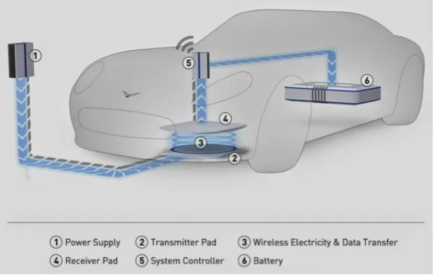
Fig. 1shows a typical wireless charging system. The power drawn from the supply is first rectified (or converted) through an AC/DC converter before being transformed to a high frequency (kHz) resonant signal by the inverter in the transmission pad installed on the ground. This energy is transferred across the air gap to the receiving pad on the vehicle through mag-netic coils. At the receiving end, it is once again rectified to charge the battery in the vehicle. Development in coil design (i.e. multiple coils, field shaping, etc.) may result in marginal improvements in the physical efficiency bandwidth; however, the weak link in the chain is the driver and how accurately they can park, or drive over the coil to maximize energy transfer efficiencies.
Inductive power transfer (IPT; also known as wireless power transfer (WPT)) as a concept has been around for almost 200 years with its roots in both Ampere’s (1826) and Faraday’s (1831) Laws. In the 1890’s Nikola Tesla demonstrated how wireless power transfer can be used to illuminate incandescent lamps in New York. From these promising beginnings the technology largely remained untapped until recent years when in 2007 a team of researchers at MIT again demonstrated transmission of 60 W across a 2.5 m air gap to illuminate a light bulb.1Concurrent development was being conducted by,
amongst others, researchers at the University of Auckland who were investigating the wireless transfer of higher power ratings suitable for powering vehicles or changing plug-in vehicles.2
In the UK the Society of Motor Manufacturers and Traders (SMMT) report that 9151 vehicles eligible for the UK Governments ‘Plug-in car grant’ – which offers a subsidy of up to £5000 off the purchase price of a plug-in vehicles (i.e. either BEV or PHEV) – have been purchased since the scheme began in January 2011 until April 2014.3This equates
to only 0.13% of new vehicle registration during this same time. Whilst this landscape is changing, as according to the same SMMT figures just over 1200 plug-in vehicles were sold in March 2014 alone, adoption rates for the uptake of EVs to the mass market is still very low. A report for the European Council suggested that the main barriers for adoption were, high purchase price, range anxiety, uncertainties associated with battery life and other factors relating to new and unfamiliar tech-nology (Wallis and Lane, 2013). Add to these the problems associated with users having to plug-in and charge the EV (as reported byWellings et al., 2010), slow refuelling rates (Pearre et al., 2011), unwillingness to find alternative transportation if needed (Tamor et al., 2013), and the fact that charging cables do not respond well in extremes of hot or cold temperatures (Boys and Covic, 2013). Those who have driven an EV will also appreciate the associated inconvenience of having to interact with a potentially dirty, wet, heavy, inflexible cable in potentially wet, cold, icy environmental conditions, as well as the time taken to physically plug the vehicle in. Wireless charging could also reduce the accidental, or malicious, unplugging of a charging vehicle as there is no physical interaction point. All of the above factors equate to possible reasons why EV own-ership has not taken off (as yet).
Whilst inductive charging will not physically increase the capacity of a battery, it may help remove the inconvenience factor of plug-in vehicles. Drivers will be able to just park their vehicle in a designated parking bay, and charging will begin automatically with no need to locate a cable and physically plug it in. A report byCarroll and Walsh (2011)suggests that ‘opportunity charging’, i.e. charging the vehicle little and often during the day when the EV is not in use, can lead to signif-icant improvements in range compared to that available from a single overnight vehicle charge. This was as a result from being able to utilise over 100% of battery state of charge per day. Such opportunistic charging may be facilitated by the inher-ent ease and convenience associated with inductive charging systems.
A review of the literature reveals that limited research has been conducted into parking behaviour, which has been pri-marily focused on parking orientation and preferences (Cullinane et al., 2004; Kobus et al., 2012), gender differences (Wolf et al., 2010), desired clearance between vehicles (Gadgil and Green, 2005), parking related crashes and incidences (Green, 2006) or vehicle-to-vehicle gap in real-world parking (Thornton et al., 2014). The most relevant study for this current paper was conducted byCullinane et al. (2004)whose research for the University of Michigan Transportation Research Institute (UMTRI) evaluated parking accuracy of 102 vehicles, in three different types of parking bays (angled, parallel and perpendic-ular). This was a retrospective analysis with participants not being aware that their parking would be assessed. Their research found no difference between the size of the vehicle and lateral parking accuracy, with drivers attempting to keep a constant amount of exit space on the drivers’ side of the vehicle in angled and perpendicular parking, and with parallel
1
http://www.sciencecodex.com/mit_demonstrates_wireless_power_transfer.
2 http://www.qualcomm.com/media/documents/files/inductive-power-transfer-systems-ipt-fact-sheet-no-1-basic-concepts.pdf. 3
parking the distance to the curb. However vehicle size did influence longitudinal clearance of perpendicular parking, with drivers more likely to overhang a ground barrier when parking a larger vehicle. The angle of parking tended to be quite small, generally less than 1°; however the range of angles was triple that for parallel parking verses angled and perpendicular park-ing (Cullinane et al., 2004).
As suggested above, it is well established that the efficiency of transfer of electrical energy through induction is highly reliant on alignment of the coils involved – in this case, the alignment between a primary coil in the parking space, and a secondary coil mounted on the vehicle. If the integration of inductive charging technology into modern vehicles is to be accepted by drivers, engineers should seek to minimise the amount of disruption to current parking behaviour. Therefore understanding the issue of parking misalignment and driver behaviour is an important human factors question, which can inform research and development in the area in order to improve the solution. However, research into this emerging technology is limited in the academic literature, and hence the focus of this paper.
2. Methodology
Two studies were conducted, one a retrospective analysis of 100 pre-parked vehicles where drivers were not aware that their parking alignment was going to be assessed when they originally parked. The second was a dynamic study where par-ticipants parked an EV aiming to align with a charging pad with no bay markings as guidance. For both studies the measure of parking accuracy, or success of the parking task, was defined by the position of the centre of the vehicle to the centre of the parking bay. This definition removed any vehicle or bay size effect from the comparative analysis.
The retrospective measurement methodology offers the benefit of naturalistic with real-world data being collected. However, it will not be able to determine the specific parking goal of the driver, or to what extent being aware their parking accuracy is being assessed will alter actual alignment. In addition no context was available as to why the driver chose to park as they did. It is entirely possible that drivers chose to park ‘misaligned’ either to allow sufficient space for them to exit the vehicle or gain access to the boot. It could be assumed that when users know they should be parking as accurately as pos-sible, an improvement in both lateral and longitudinal control will be observed. This was the intention and purpose of the second, dynamic study.
2.1. Retrospective analysis
One hundred vehicles were randomly selected for measurement from three different car parks on the main campus of the University of Warwick. Vehicles were already parked when measurement were taken. Assessment took place over a two week period during July 2013, with physical measurements being taken between 10:00–12:00 and 14:00–16:00.
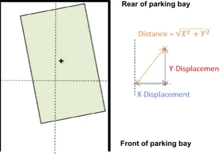
[image:4.544.115.427.55.252.2]The three car parks selected for the study were all perpendicular bays, with a white ‘T’ to identify the front of the parking bay, and either a white dash or with no markings at the rear of the bay (Fig. 2). Irrespective of parking orientation the ‘front’ of the bay was always defined as the head or opening of the bay and identified with the white ‘T’. The rear of the bay was always identified as having a barrier beyond the parking area. This barrier would either be a ‘hard’ steel barrier or ‘soft’ shrubbery barrier. The full car park characteristics are outlined inTable 1below:
2.2. Measured and derived variables
To measure the actual parking alignment of vehicles they were simply modelled as rectangles located in a rectangular bay. The principal method of data collection for determining parking bay and vehicle size was by physical measurement and other relevant observations. From this numerous different parameters (Fig. 3) could be derived, including:
Measured Variables
Length and width of parking bay: These were measured by tape measure, from the back of the bay to the front (includ-ing line mark(includ-ings), and between the inside of both ‘‘T’’ or parallel marks.
The length, width and wheelbase of the vehicle: These were measured by tape measure, between markers which were set down on the floor at the points at which the corners of the ‘‘vehicle’’ rectangle in the model would be located.
The distance from vehicle to side of bay: Perpendicular distance from corner of the vehicle to the side of the parking bay, taken from the two opposing corners of the vehicle that were closest to the bay lines, made using a tape measure.
The closest distance between the vehicle and the rear of the bay: Measured using a tape measure.
The orientation of the vehicle: Reversed or driven in.
The general category of vehicle: From a pre-determined list of types.
Parking aids: If fitted, i.e. none, rear or both (front and rear).
Derived Variables
Location of the centre of the vehicle and parking bay: Derived with respect to a coordinate system with origin in the centre of the bay.
Parking Angleof the vehicle to the bay, in degrees.
Displacementof centre of vehicle from the centre of the bay in both lateral (x) and longitudinal (y) axis, in cm.
Distanceof centre of vehicle from the centre of the bay in both lateral (x) and longitudinal (y) axis, in cm. Distance is the absolute value of the displacement, i.e. if they were away from the centre of the bay, then by how far.
Distance from Centre: Distance the centre of vehicle is away from the centre of bay, in cm. As stated previously this is the primary measure for parking accuracy used in this study, and forms the basis of the statistical analysis.
2.3. Dynamic parking study
[image:5.544.86.461.56.150.2]A second, pilot study was conducted to evaluate how participants parking accuracy was affected when they were aware of the aims of the study, i.e. to evaluate their accuracy when parking a Nissan Leaf EV over a simulated inductive charging pad (7758 cm in size) with no bay marking. This scenario was established in order to gain a true understanding of parking accuracy with no barriers, markings or other vehicles to offer alignment guidance (Fig. 4). In addition this could be consid-ered an appropriate scenario for charging on a driveway at home. Ten participants (five male and five female) took part in this dynamic study, with data collection taking place on a secluded section of private road on the main campus at the University of Warwick. The scenario started with the vehicle being parked at the approximate location of the red4‘dot’ in
Fig. 2.Car Parks (left to right) 8, 8a and 10b.
Table 1
Characteristics of the three cars parks and associated bays from which vehicles were measured.
Car park Front marker Rear marker Rear barrier Side barrier No of cars Ave length (cm) Ave width (cm)
8 T None High & Hard Car or Hard 41 476.1 228.9
8a T Dash High & Soft Car or Soft 47 483.4 234.5
10b T Dash Low & Soft Car or Soft 12 467.8 217.8
4
[image:5.544.44.497.206.251.2]Fig. 4, from here the participant drove the vehicle down a short straight and turned left at the corner in order to align and park over the charging pad. The road was 5.6 m wide, with no marking apart from double yellow lines down both sides. The pad was located 2.4 m from the left edge of the road, and 3.5 m from the end of the road, i.e. not centrally which would have given the driver something to align the vehicle to when parking, ensuing it was a truly freeform parking scenario (Fig. 4). All of the par-ticipants were registered to drive a University owned vehicle on the Universities insurance policy, but were not experienced at driving the Nissan Leaf EV. For this reason a researcher was always present within the vehicle to advise on vehicle operation, give study instructions and deal with any questions surrounding the study.
Two conditions were adopted based on what part of the vehicle was being aligned over the target charging pad, these were either the ‘front’ or ‘centre’ of the vehicle. These were selected based on current locations of actual wireless charging demonstrator vehicles which have been produced. Participants were simply instructed to ‘park accurately with the front/centre of the vehicle over the charging pad’. The order that the two conditions were completed was randomised. Participants were allowed to manoeuvre the vehicle and make positional adjustments until they were happy with their final position. However, in practice all participants were satisfied at the first attempt. Parking accuracy was again assessed by physical measurement, as per the retrospective analysis, with the derived variables described previously being the principal measures.
2.4. Data collection and analysis
Raw data were collected via physical measurement with a tape measure, collated on a data entry sheet, and then trans-ferred to IBM SPSS Statistics 21 for analysis. Data for vehicles which had been reversed into the parking spaces in the retro-spective analysis were inverted for the analysis. Meaning that if the driver parked off-centre laterally (i.e. leaving more space either to the driver or passenger side) then this would not be lost in the analysis. A One-Way ANOVA was used to determine statistical significance, and was accepted atp< 0.05.
Ethical approval was granted for the study by the University of Warwick’s Biomedical and Scientific Research Ethics Committee (BSREC). For the retrospective analysis it was agreed that no identifying features of the vehicle would be recorded (e.g. photographs of assessed vehicles, number plates, gender of driver, etc.), and in the case of approach by a member of
Rear of parking bay
Front of parking bay
[image:6.544.163.377.55.206.2]+
[image:6.544.115.426.559.676.2]Fig. 3.Example of how the derived data was calculated; + represents the centre of the vehicle ‘rectangle’ and dotted lines within the bold black lines the centre of the bay ‘rectangle’.
public the researchers would offer a verbal and written explanation of the study, and give the opportunity for the driver of a measured vehicle to have their data removed.
3. Results
3.1. Retrospective analysis
Below are results from the objective measures of vehicle classification from the 100 vehicles analysed in the retrospective analysis.Table 2shows that the majority of vehicles evaluated were hatchback, with no parking sensors and had been driven forward into the parking bay.Table 3shows that on average vehicles tended to park towards the left of the bay (with anx -displacement of 3.1 cm), and the rear of the bay (y-displacement 15.6 cm), regardless of orientation. The mean angle of parking was 0.02°.
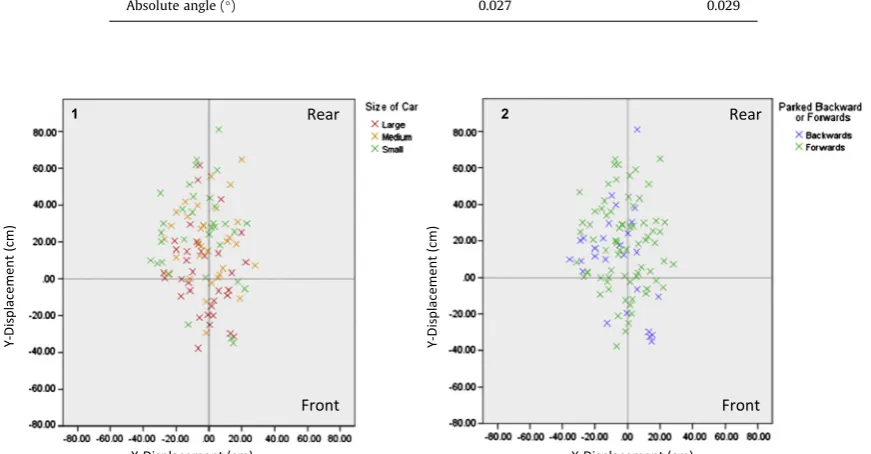
Graph 1 inFig. 5shows the distribution ofxandycoordinates of the centre of the 100 vehicles in this sample, coloured by size of vehicle (determined by separating the data equally into three groups, based on the area of the vehicle base, widthlength). Statistical analysis showed that there was an overall significant difference in the data set (F(2,99)= 7.91,
p< 0.001), with post hoc analysis (Bonferroni corrected) showing that small vehicles were parked significantly less accu-rately (i.e. a greater ‘distance from centre’) than both medium (p< .0.05) and large (p< 0.001) vehicles, with no difference between medium and large (p> 0.05). Graph 2 illustrates parking accuracy in relation to orientation of parking (i.e. driven forward into the bay or reversed). There was no difference between the two orientations with respect to distance from the centre of the bay (F(1,99)= 0.10,p> 0.05).Fig. 6shows the distance to the rear of the parking bay (i.e. centrey-distance) for the
different car park barrier types.
Parking aids are deigned to assist specifically with the longitudinal aspect of parking. Results showed that parking sensors significantly (F(2,89)= 8.83,p< 0.001) increased the accuracy, as defined by the distance of the centre point of the vehicle from
the centre point of the bay, of parking alignment in this study (Fig. 7).
3.2. Dynamic parking study
Table 4shows results from the dynamic study. Parking was generally more accurate in the lateral direction when aligning the front of the vehicle over the charging pad in comparison to the centre of the vehicle (meanx-displacement of 0.5 verses 7.3 cm respectively). This difference was statistically significant (F(1,19)= 9.02,p< 0.05). As with the retrospective analysis
accuracy in longitudinal axis was again inferior, with drivers generally parking short of the charging pad target with both front (y-displacement = 66.86 cm) and centre ( 34.05 cm) parking conditions. Interestingly though, the distance the centre of the car was away from the centre of the charging pad was similar for both conditions at approximately 75 cm (Table 4).
4. Discussion
Two studies were conducted both with different objectives. The first a retrospective analysis of how people park with clear limiting variables such as bay markings and barriers, but not being aware that their parking was being evaluated. The second a free-form parking task, with only a 7758 cm charging pad as a target. Understanding how people park in these two situations will offer important insights and help designers to develop enhanced inductive charging systems, which have the potential to facilitate the uptake and convenience of plug-in vehicles.
4.1. Retrospective analysis
The elliptical nature of the spread of data inFig. 5, with thex-mean at approximately zero andy-mean at approximately 15 cm, suggest that vehicles were parked more accurately in the lateral (orx) direction compared to the longitudinal (y) direction. The spread in the data also reflects this, with the range of lateral accuracy at around 60 cm which was approxi-mately half that of the longitudinal range.Table 3shows that the mean lateral distance was 12.1 cm (either to the left or right), with a mean displacement of 3.2 cm to the left of the bay (i.e. more clearance on the driver compared to passenger side). Research conducted by Cullinane et al. (2004) showed that in a comparable study conducted in Ann Arbor, Michigan, US, vehicles were parked with an average of 10.4 cm clearance on the drivers’ side (right in the case of the US). This increased lateral offset may be a function of the average bay width in the US study being 47 cm wider than in the current study, or may simply be a cultural preference.
sensors increased the accuracy of parking alignment. Whilst parking sensors inform the driver of their distance to a rear bar-rier, and not the centre of the bay, the real-world application of this suggested that those without sensors were more likely to overhang the front of the bay or misjudge their longitudinal position within a bay. Therefore a secondary effect of parking sensors was better assessment of distance to rear barrier, which was directly linked to centrality within the bay. Of the 21 vehicles that had parking sensors, 13 were large vehicles with the remaining 8 medium sized vehicles. The four vehicles with front and rear sensors were all large vehicle, conversely no small vehicles had parking sensors fitted. Another possible reason for the increased ‘accuracy’ of larger vehicles is that the vehicle to bay ratio is smaller, meaning they have less space allow-ance to ‘play with’ when parking. Not parking centrally within a bay could increase the risk of the vehicle either overhanging the front or rear of the bay, both of which may result in physical damage to the vehicle. Smaller vehicles may choose to posi-tion themselves to allow for ease on exiting the vehicle, or choose to give a vehicle parked at the side more clearance and hence reduced risk of damage to their vehicle, but resulting in reduced accuracy.Cullinane et al. (2004)also found that vehi-cle size affected longitudinal accuracy, with drivers of a large vehivehi-cle more likely to overhang a ground (low) barrier.
[image:8.544.37.505.73.144.2]An interesting occurrence was the adaptation to parking behaviours with the presence of a ‘hard’ rear barrier, in this case a steel structure in car park 8 (Fig. 2).Fig. 6shows that the distribution of distance to rear of the bay when either a low or soft
Table 2
Objective measures of vehicle classification.
Type of vehicle N Parking sensors N Orientation N
Hatchback 64 Unknown 10 Reversed 27
Sedan 25 None 69 Forward 73
SUVs 5 Rear only 17 Total 100
Coupe 5 Rear & Front 4
Vans 1 Total 100
[image:8.544.108.433.201.279.2]Total 100
Table 3
Mean displacement and distance in thex(lateral) andy(longitudinal) axis, and distance from the centre of the vehicle to the centre of the bay. Distance is the absolute value of the displacement, i.e. if they were away from the centre of the bay, then by how far.
Mean S.D.
X-displacement (cm) 3.21 14.64
Y-displacement (cm) 15.59 25.02
Distance from centre (cm) 29.30 15.13
X-distance (cm) 12.12 8.74
Y-distance (cm) 23.73 29.12
Parking angle (°) 0.018 2.27
Absolute angle (°) 0.027 0.029
X-Displacement (cm) X-Displacement (cm)
Y-Di
sp
la
ce
me
nt
(c
m)
Y-Di
sp
la
ce
me
nt
(c
m)
2 1
Front
Front
Rear
Rear
[image:8.544.53.489.268.495.2]barrier is present (graph 1) could be considered normal, with the most frequent distance being 10–20 cm from the rear barrier. Whilst 10–20 cm is still the most frequent distance for when a hard barrier is present (graph 2), the distribution could not be considered normal, but either chi-squared or bimodal. A second peak in the data occurs a distance of
[image:9.544.146.405.270.478.2]Fig. 6.Distance from the most distal point of the vehicle to the rear of the parking bay. Data presented in graph 1 from Car Park 8a and 10b (low or soft rear barriers), graph 2 from Car Park 8 (high and hard).
Fig. 7.The presence of parking sensors on the accuracy of parking.
Table 4
Mean displacement and distance in thex(lateral) andy(longitudinal) axis, and distance from the centre of the vehicle to the centre of the charging pad. Distance is the absolute value of the displacement, i.e. if they were away from the centre of the bay, then by how far.
Front Centre
Mean S.D. Mean S.D.
X-displacement (cm) 0.54 7.21 7.33 15.07
Y-displacement (cm) 66.86 60.81 34.05 92.09
Distance from centre (cm) 75.39 49.01 75.93 60.41
X-distance (cm) 5.95 3.61 13.20 9.64
Y-distance (cm) 74.65 49.71 72.31 62.92
Parking angle (°) 2.00 2.14 0.18 5.64
[image:9.544.43.508.543.635.2]40–50 cm, and may indicate the difficultly that people have judging the distance that their vehicle is away from the rear of the parking bay. It is at this point when in-vehicle feedback could be given to the driver to encourage more accurate longi-tudinal alignment.
The mean angle of parking was 0.02°, even in absolute form this was only 1.6°(Table 3). Whilst this implies that in general vehicles were parked straight on in the bay, the range of the data again reveals greater differences of 15.8°(6.7 to 9.1°). Interestingly results fromCullinane et al. (2004)showed that whilst the mean angle was very small (and similar to the pre-sent study) at 0.1°, the range of the vehicles they recorded was significantly smaller at just 1.4°. This difference may be a function of the smaller number of vehicles evaluated parking in a bay (or perpendicular) with the Cullinane study (36 verses 100), or possible infrastructure aspects such as wider bays or expansive parking lots.
4.2. Dynamic parking study
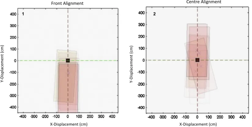
Results from the dynamic study clearly show that parking alignment accuracy in the lateral direction was superior when drivers were ask to align the front of the vehicle over the charging pad (mean distance from centre = 5.9 cm), compared to both dynamically aligning the centre of the vehicle (13.2 cm) and also assessed in the retrospective study (12.1 cm). The same was true for both displacement from the centre point and also reduced spread in the data assessed by standard devi-ation (Table 4).Fig. 8shows this graphically for the dynamic study.
Reasons for the increased accuracy in the lateral direction when aligning the front of the vehicle over the charging pad may be the simple fact that the target location was out of the driver’s view for a shorter period of time. If driving forward for an additional 1.42 m (the distance between the ‘front’ and ‘centre’ point of the vehicle evaluated in this study) any slight misalignment of the vehicle will be exaggerated. It can be calculated that even if the front of the vehicle is aligned with the centre of the charging pad, the angle of driving trajectory only needs to be off by 4°for the centre point of the vehicle to be misaligned with the charging pad after 1.42 m of travel. This highlights the sensitivity of trying to align a vehicle over a target which is out of the driver’s field of view.
An interesting occurrence is seen with longitudinal alignment, whilst the meany-displacement that participants stopped short of the charging pad was smaller (although not significant,p> 0.05) when parking the centre of the vehicle over the charging pad compared to the front, at 34.1 to 66.9 cm, the mean distance (i.e. if there were away from the centre of the bay how far was this) was very similar at 74.7 and 72.3 cm respectively (Table 3). The standard deviations fory -displace-ment and distance in Table 3show when aligning the front of the vehicle over the charging pad participants generally stopped short of it (Fig. 8; in fact only one participant overshot, compared to three with centre), they were far more consis-tent in their judgement of distance and needed only smaller longitudinal adjustments.
4.3. Inductive charging compatibility
An important consideration for this paper is the impact that parking alignment has on inductive charging systems in the real-world, and subsequently understanding the proportion of drivers who currently park within the tolerances of such sys-tems. For this, two systems were considered; ‘System A’ has tolerances of 15 cm in both the lateral (x) and longitudinal (y) axis and ‘System B’ 10 cm in thexand 20 cm in theyaxis. The dimensions selected reflect two different approaches to coil design, and are representative of inductive charging systems currently on the market.
The data suggest, andFig. 9shows, that in both the dynamic and retrospective studies only 5% of vehicles assessed in this paper parked within alignment tolerances for both inductive charging systems A and B. Meaning alignment of the two coils would not be sufficiently accurate to allow power transfer to be initiated at even a level of 80% transfer efficiency.Fig. 9also shows the range of alignment that developers of these systems for plug-in vehicles need to contend with, particularly in the longitudinal (ory) direction.
How to facilitate users to park within tolerances of inductive charging systems is a difficult human factors and engineer-ing challenge; which cannot feasibly be solved by simply makengineer-ing the inductive coils larger. This is not a cost effective solu-tion, also vehicle manufacturers will have packaging difficulties fitting a larger coil to the underside (and exposed aspect) of a vehicle. It may be addressed by technology, and specifically park assist systems. Results from this study showed that the presence of parking sensors on a vehicle significantly (p< 0.001) increased parking accuracy. Automated parking is already a feature on many premium vehicles, which could be used to park the vehicle accurately over the primary inductive coil in the bay. However, automated parking systems are a new and expensive technology which are typically only available for a limited range of parking manoeuvers. In addition it is still unclear if parking is considered as between two vehicles or two lines (namely the centre of the bay), as this will have an obvious effect on alignment.
longitudinal alignment (Fig. 8) is by far the greatest source of alignment inaccuracy and would benefit the most from in-ve-hicle feedback.
5. Conclusions
Whilst manufacturers claim inductive charging technology is market ready, the efficiency of transfer of electrical energy is highly reliant on accurate alignment of the coils involved, hence driver behaviour and parking alignment was the focus for this paper. Results from both the retrospective and dynamic studies suggest that drivers are more accurate at parking lat-erally than in the longitudinal direction. A reason for this may be that drivers can align the sides of the vehicle as a guide, whereas judging the position of the front or rear of the car is more difficult (without parking aids). Larger vehicles and the presence of parking sensors also had a significant positive effect on parking accuracy. Current inductive charging systems
Front Alignment Centre Alignment
Y-D
isp
la
ce
m
en
t
(c
m
)
Y-D
isp
lac
em
en
t
(cm
)
2 1
[image:11.544.70.483.56.264.2]X-Displacement (cm) X-Displacement (cm)
Fig. 8.Representation of parking alignment for the dynamic study, each red ‘vehicle’ represents one of the 10 participants,xandyaxis represents distance from the centre of the bay. Graph 1 shows this for the alignment of the front of the vehicle over the centre of the charging pad, and graph 2 the centre of the vehicle. (For interpretation of the references to colour in this figure legend, the reader is referred to the web version of this article.)
X-Displacement (cm) X-Displacement (cm)
Y-Di
sp
la
ce
me
nt
(c
m)
Y-Di
sp
la
ce
me
nt
(c
m)
2 1
[image:11.544.56.490.321.519.2]typically have misalignment tolerances of approximately ±10 cm from their centre point. The distribution of parking accu-racy observed in this paper were between 120 and 280 cm in the longitudinal direction and 20–60 cm laterally. This resulted in only 5% of vehicles in both studies being aligned sufficiently accurately to allow efficient transfer of electrical energy through induction.
Future research should be conducted to substantiate results from the dynamic study. This paper presents a ‘pilot’ analysis with only 10 participants, one parking scenario, and two conditions. Future research should focus on incorporating different parking tasks, such as parallel and bay parking, and also increasing the number of participants evaluated. Some unanswered questions still remain about the impact of vehicle size on parking accuracy. An interesting finding from this study was that larger vehicle parked more accurately (i.e. the centre of the vehicle was closer to the centre of the bay) compared to smaller ones; however, we were not able to determine if this was as a result of the presence of parking sensors on larger vehicles, or personal preference of smaller vehicle drivers to park ‘less accurately’.
5.1. Recommendations for future inductive charging systems
Based on results presented in this paper the authors have made some recommendations for consideration when design-ing future inductive chargdesign-ing systems or driver feedback systems, these are:
Locate the vehicle mounted secondary coil towards the front of the vehicle in order to facilitate an increase in lateral alignment by the driver.
In-vehicle feedback should focus on longitudinal advice as this is the greatest source of alignment inaccuracies.
Longitudinal feedback should start to be given at approximately 50 cm prior to the target, as this is where a ‘second peak’ of parking misalignment occurred.
A potential solution would be to offer lateral alignment advice at distances greater than 50 cm, then longitudinal feedback at less than 50 cm.
Parking sensors should be adopted as they have a positive effect on parking accuracy.
The combination of automated park assist and inductive charging would offer a ‘premium solution’ to the issues associ-ated charging a plug-in vehicle.
References
Boys, J., Covic, G., 2013. ‘‘IPT Fact Sheet Series: No. 1 – Basic Concepts’’. < http://www.qualcomm.com/media/documents/files/inductive-power-transfer-systems-ipt-fact-sheet-no-1-basic-concepts.pdf> [Accessed 16.05.14].
Carroll, S., Walsh, C., 2011. ‘‘The Smart Move case studies’’, Cenex, Holywell Park, Loughborough University, LE11 3TU, UK. Technical Report.
Cullinane, B., Smith, D., Green, P., 2004. Where, When and How Well People Park: A Phone Survey and Field Measurements, The University of Michigan Transportation Research Institute (UMTRI), US, Technical Report UMTRI-2004-18.
Gadgil, S., Green, P., 2005. How much clearance drivers want while parking: data to guide the design of parking assistance system. In: Proceedings of the Human Factors and Ergonomics Society 49th Annual Meeting, pp. 1935–1939.
Green, P., 2006. Parking Crashes and Parking Assistance System Design: Evidence from Crash Databases, the Literature, and Insurance Agent Interviews, SAE Technical Paper 2006-01-1685.
He, F., Yin, Y., Zhou, J., 2013. Integrated pricing of roads and electricity enabled by wireless power transfer. Transp. Res. Part C 34, 1–15.
ICNIRP, 2010. Guidelines for limiting exposure to time-varying electric and magnetic fields (1 Hz to 100 kHz). Health Physics 99 (6), 818–836. IEEE, 1992. IEEE Standard for Safety Levels with Respect to Human Exposure to Radio Frequency Electromagnetic Fields, 3 kHz to 300 GHz, IEEE Std.
C95.1:1992, New York, NY.
Kobus, M., Gutierrez-i-Puigarnau, E., Rietveld, P., Van Ommeren, J., 2012. The on-street Parking Premium and car drivers’ Choice between Street and Garage Parking. Tinbergen Institute, The Netherlands, TI2012-040/3.
Pearre, N., Kempton, W., Guensler, R., Elango, V., 2011. Electric vehicles: how much range is required for a day’s driving? Transp. Res. Part C 19, 1171–1184. Stanton, S., 2014. Simulation-driven product development for wireless power transfer. In: IEEE Wireless Power Transfer Workshop, University of Michigan,
Dearborn, 13th March 2014.
Tamor, M., Gearhart, C., Soto, C., 2013. A statistical approach to estimating acceptance of electric vehicles and electrification of personal transportation. Transp. Res. Part C 26, 125–134.
Thornton, D., Redmill, K., Coifman, B., 2014. Automated parking surveys from a LIDAR equipped vehicle. Transp. Res. Part C 39, 23–35.
Wallis, N., Lane, B., 2013. Electric vehicles: Improving consumer information to encourage adoption. European Council for Energy Efficient Economy, Technical Report: 4-514-13.
Wellings, T., Binnersley, J., Robertson, D., Khan, T., 2010. Human machine interfaces in low carbon vehicles: Market trends and user issues, Low Carbon Vehicle Technology Project, Technical Report: HMI 2.0.