A Framework for Building Customised
CORBA ORBs
A thesis submitted to the
University of Dublin, Trinity College,
In fulfilment of the requirements for the degree of
Master of Science (Computer Science)
Hubertus Wiese, BE, H.Dip.App.Sc.,
Department of Computer Science,
Trinity College, Dublin
Declaration
I, the undersigned, declare that this work has not previously been submitted as an exercise for a degree at this or any other University, and that, unless otherwise stated, it is entirely my own work.
_____________________
Hubertus Wiese
September 1998
Permission to Lend and/or Copy
I, the undersigned, agree that Trinity College Library may lend and/or copy this thesis upon request.
_____________________
Hubertus Wiese
Summary
Recently, many distributed applications have been based on Common Object Request Broker Architecture (CORBA) compliant middleware. Such distributed computing middleware provides the components of a distributed application with a uniform view of local and remote application objects. It shields distributed application programmers from having to deal with network and protocol layers and lets them concentrate on the design of the distributed application itself.
To date, most CORBA compliant Object Request Brokers (ORBs) have been based on monolithic implementations. Vendors typically offer the same ORB implementation for use in any number of different application scenarios. Recently, some ORB implementations have appeared that target specific application domains, for example real-time applications and fault-tolerant applications. These ORBs, however, focus on one specific application scenario.
The purpose of this thesis is to explore the alternative approach of designing not a “one size fits all” ORB, but rather an object-oriented framework that allows
application developers to instantiate their own customised ORBs from components available in the framework. Thus, one user may, for example, use the framework to create a “standard” ORB supporting mobile computing, or fault-tolerance.
In order to understand the characteristics of ORBs in general, and of those aimed at specific application domains in particular, a number of freely available ORBs were studied. From this, it was possible to infer which components are commonly found in ORBs aimed at specific application scenarios.
Acknowledgements
I would like to thank my supervisor, Dr. Vinny Cahill, for the many discussions we had and for the suggestions and advice he has given me throughout this project.
Thanks also to Jim Dowling for numerous discussions we had on CORBA and frameworks in general.
Table of Contents
INTRODUCTION...11
1.1 The Problem... ... 11
1.2 Proposed Solution... 12
1.3 Achievements ... 12
1.4 Format of Thesis... 13
1.5 Summary ... 13
SURVEY ...14
2.1 Introduction ... ... 14
2.2 Design Patterns ... 14
2.2.1 A Design Pattern Example: Facade ... 15
2.3 Frameworks ... 16
2.3.1 Introduction to Frameworks ... 16
2.3.2 Characteristics of Frameworks ... 17
2.3.3 Types of Framework ... 18
2.3.4 Frameworks in relation to other approaches to reuse ... 19
2.3.5 Examples of Frameworks ... 20
2.3.6 Strategies for developing Frameworks ... 21
2.3.6.1 A Pattern Language for developing Frameworks ... 21
2.3.7 Documenting Frameworks ... 23
2.3.8 Problems regarding Framework Development ... 23
2.4 CORBA and Frameworks ... 24
2.4.1 Introduction to CORBA Object Request Brokers ... 24
2.4.2 Some CORBA Application Scenarios ... 26
2.4.2.1 Reliable Distributed Systems... 26
2.4.2.2 Performance in CORBA Distributed Systems... 26
2.4.2.3 Mobile Distributed Systems ... 27
2.4.2.4 Developing a Framework for Customisable ORBs ... 28
2.5 Summary ... 29
ANALYSIS OF EXISTING OBJECT REQUEST BROKERS...30
3.1 Introduction ... 30
3.2 OmniORB ... 30
3.2.1 Introduction ... 30
3.2.2 Purpose of the analysis ... 31
3.2.3 Main features of OmniORB2 ... 31
3.2.3.1 CORBA 2 compliancy... 31
3.2.3.2 Platform support ... 31
3.2.3.3 Missing features ... 31
3.2.4 Building and testing OmniORB2 ... 32
3.2.4.3 Makefiles ... 32
3.2.4.4 Tools and methods used for analysing OmniORB ... 33
3.2.4.5 Problems encountered ... 33
3.2.5 Overall architecture of the ORB... 34
3.2.5.1 The ORB ... 34
3.2.5.2 The BOA ... 34
3.2.5.3 Sample skeleton code generated by the IDL compiler ... 35
3.2.5.4 The OmniThread library... 36
3.2.5.5 Implementation of GIOP and IIOP... 36
3.2.6 Conclusion... 41
3.3 TAO ... 41
3.3.1 Introduction ... 41
3.3.2 Purpose of the analysis ... 41
3.3.3 Main features of TAO ... 41
3.3.3.1 Realtime ORB core ... 42
3.3.3.2 Optimised Object Adapter... 42
3.3.3.3 Realtime IDL (RIDL) QoS specification... 42
3.3.3.4 IDL compiler optimisations... 42
3.3.3.5 Memory Management Optimisations ... 42
3.3.3.6 Platform support ... 43
3.3.4 Building and testing TAO ... 43
3.3.4.1 The documentation ... 43
3.3.5 Overall Architecture of the TAO ORB... 43
3.3.5.1 The ACE Framework ... 43
3.3.5.2 Design Patterns in ACE... 46
3.3.5.3 The TAO ORB ... 50
3.4 Electra ... 52
3.4.1 Introduction ... 52
3.4.2 Purpose of the analysis ... 52
3.4.3 Main features of Electra ... 53
3.4.3.1 CORBA compliancy... 53
3.4.3.2 Platform support ... 53
3.4.3.3 Facility for object groups... 53
3.4.4 Overall architecture of the Electra ORB... 54
3.5 Conclusion... 57
DESIGN OF THE OBJECT REQUEST BROKER FRAMEWORK ...59
4.1 Introduction ... 59
4.2 Framework Requirements... 60
4.2.1 Whitebox Framework... 60
4.2.2 CORBA specified components... 63
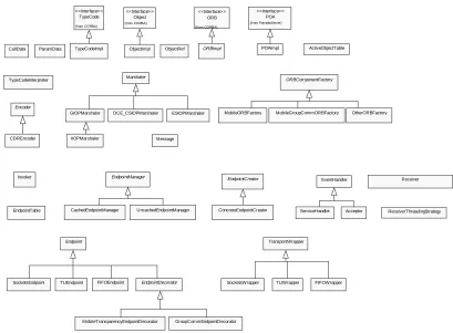
4.3 Framework Design ... 64
4.3.1 Overall Design... 64
4.3.2 Core Components ... 65
4.3.2.1 ORBImpl ... 65
4.3.2.2 ORBComponentFactory ... 65
4.3.2.3 Marshaler... 66
4.3.2.4 TransportWrapper ... 73
4.3.2.5 Endpoint ... 74
4.3.3 Components for client functionality ... 77
4.3.3.1 Invoker ... 77
4.3.4 Components for server functionality ... 79
4.3.4.2 POAImpl ... 81
4.3.5 Principal design patterns used in the framework ... 82
4.3.5.1 Abstract Factory ... 82
4.3.5.2 Adapter ... 83
4.3.5.3 Builder... 84
4.3.5.4 Decorator... 84
4.3.5.5 Singleton... 85
4.3.5.6 Strategy... 86
4.4 Summary ... 87
EVALUATION OF THE OBJECT REQUEST BROKER FRAMEWORK...88
5.1 Introduction ... 88
5.2 Creating customised Object Request Brokers ... 88
5.2.1 Creating a concrete ORBComponentFactory ... 88
5.2.2 Creating a concrete EndpointCreator ... 90
5.2.3 Inheriting from other abstract framework classes... 90
5.3 A sample object invocation ... 91
5.3.1 Sample Object Invocation: Client Side ... 92
5.3.2 Sample Object Invocation: Server Side... 95
5.4 Summary ... 97
CONCLUSION ...98
6.1 Introduction ... ... 98
6.2 Problems with the framework approach... 98
6.3 Implementing the framework... 100
List of Figures
Figure 1 Facade Design Pattern ... 16
Figure 2 Evolving Frameworks ... 23
Figure 3 OmniORB Stub and Skeleton Classes... 35
Figure 4 OmniORB Omni Thread Library Classes ... 36
Figure 5 OmniORB Rope Inheritance Hierarchy ... 36
Figure 6 OmniORB Rope Factory Inheritance Hierarchy ... 37
Figure 7 OmniORB Strand Inheritance Hierarchy ... 38
Figure 8 OmniORB Endpoint Inheritance Hierarchy ... 38
Figure 9 OmniORB GIOP Inheritance Hierarchy ... 39
Figure 10 OmniORB Worker And Rendezvouser Inheritance Hierarchy ... 40
Figure 11 ACE Framework Layers... 44
Figure 12 ACE IPC Class Hierarchy ... 45
Figure 13 ACE Classes For Concurrency... 45
Figure 14 Acceptor Connector Design Pattern ... 46
Figure 15 Reactor Design Pattern ... 48
Figure 16 Service Object Inheritance Hierarchy ... 49
Figure 17 Service Repository Class Composition ... 49
Figure 18 Service Configurator Design Pattern... 50
Figure 19 TAO Components... 50
Figure 20 TAO ORB Core... 51
Figure 21 Some Possible Electra Configurations ... 55
Figure 22 Electra Adapter Classes... 56
Figure 23 Electra AdaptorData Classes ... 56
Figure 24 Electra ORB Layering ... 57
Figure 25 Factory Method Design Pattern... 61
Figure 26 Template Method Design Pattern... 62
Figure 27 ORB Framework Hierarchy ... 64
Figure 28 ORB Component Factory... 66
Figure 29 Marshaler Inheritance Hierarchy ... 67
Figure 30 Message Class ... 68
Figure 31 CallData Class Composition ... 69
Figure 32 Encoder Inheritance Hierarchy... 71
Figure 33 Marshaler Class Composition ... 72
Figure 34 Transport Wrapper Inheritance Hierarchy... 73
Figure 35 Endpoint Inheritance Hierarchy ... 75
Figure 36 Invoker Class Composition ... 78
Figure 37 Receiver Class Composition ... 80
Figure 38 POAImpl Class Composition ... 81
Figure 39 Abstract Factory Design Pattern... 82
Figure 40 Adapter Design Pattern ... 83
Figure 41 Builder Design Pattern ... 84
Figure 42 Decorator Design Pattern ... 85
Figure 43 Singleton Design Pattern ... 86
Figure 44 Strategy Design Pattern ... 86
Figure 45 Calculator Stub And Skeleton Classes ... 92
Figure 47 Cube Invocation: Client Side Marshaling ... 94
Figure 48 Cube Invocation: Client Side Invocation ... 94
Figure 49 Cube Invocation: Client Side Unmarshaling... 95
Figure 50 Cube Invocation: Server Side Overall View ... 96
Chapter 1
Introduction
1.1
The Problem
The Object Management Group (OMG) Common Object Request Broker Architecture (CORBA) is an emerging standard that combines the fields of distributed computing and object oriented programming. An Object Request Broker (ORB) is a piece of software that enables the implementation of distributed applications that use the object oriented paradigm. ORBs are also known as middleware.
Recently, many distributed applications have been based on the CORBA standard by using CORBA compliant ORBs as middleware. Such middleware provides the components of a distributed application with a uniform view of local and remote application objects. It shields distributed application developers from having to deal with network and protocol layers and lets them concentrate on the design of the distributed application itself.
Most CORBA compliant ORBs have been based on monolithic implementations. Vendors typically offer a single ORB implementation for use in any
implementing a distributed application, than having to worry about implementing the required middleware.
1.2
Proposed Solution
This thesis proposes that an object-oriented ORB framework would allow an application developer to focus on the distributed object application at hand, while providing him or her with the ability to easily implement the required ORB middleware, tailored to the particular application scenario. Such a framework provides the architectural design for any ORB created by instantiating it.
In order to arrive at a design for an ORB framework, a number of steps were
taken. First, the CORBA specification was studied in detail in order to understand the requirements of a CORBA compliant ORB. In addition to this, the process of designing and developing frameworks in general was studied. Particularly relevant to this study was the area of object-oriented design patterns, which pervade most frameworks.
Next, a number of publicly available CORBA compliant ORBs were analysed. These included one ORB aimed at general distributed object applications, and two ORBs aimed at specific application areas. The findings of this analysis influenced the requirements formulation of the framework design and the design of the framework itself.
Finally, the actual ORB framework was designed. The design was documented using Unified Modeling Language (UML) object and sequence diagrams. Design patterns played an important role in the design of the framework.
1.3
Achievements
A number of things were achieved by this project. Firstly, a design for an ORB framework was developed. The design includes UML object and interaction diagrams. C++ class definitions were also created. These can be used in a possible future implementation of the framework.
gained in framework development in general, especially with regard to problems encountered in framework design.
Insight was gained into the OMG CORBA specification and how it can be
implemented, by the analysis of various publicly available CORBA ORBs.
1.4
Format of Thesis
The following chapter is a survey of CORBA and frameworks in general. Chapter 3 is an analysis of three publicly available ORBs. Chapter 4 describes the design of the ORB framework. Chapter 5 is an evaluation of the framework. Finally, Chapter 6 finishes with some concluding remarks about the project.
1.5
Summary
Chapter 2
Survey
2.1
Introduction
The purpose of this chapter is to introduce some of the concepts and areas of research that are relevant to this project. The survey begins with a brief introduction to design patterns. Design patterns are relevant to both framework and ORB design. Next, frameworks are introduced and some characteristics of frameworks are given. Some different types of framework are explained, and frameworks are compared to other types of software reuse. Strategies for framework development are also outlined. After frameworks are discussed, the CORBA architecture is briefly introduced. Some possible
CORBA application scenarios are described. Finally, the approach to developing the framework is discussed.
2.2
Design Patterns
Design patterns play an important role in framework design. Since they will be referred to in subsequent sections, they are briefly introduced at this point. The idea of design patterns was adopted from the field of architecture where it was first formulated
problem which occurs over and over again in our environment, and then describes the core of the solution to that problem, in such a way that you can use this solution a million times over, without ever doing it the same way twice”.
This idea also sums up design patterns in object-oriented software design. A design pattern systematically names, motivates, and explains a general design that addresses a recurring design problem in object-oriented systems. It describes the problem, the solution, when to apply the solution, and its consequences. It also gives implementation hints and examples. The solution is a general arrangement of objects and classes that solve the problem. The solution is customised and implemented to solve the problem in a particular context [Gam95].
The seminal work on design patterns is [Gam95]. In it, the authors catalog some 23 design patterns which were found to recur over and over again in well designed object oriented application designs. A pattern consists of four major parts: the pattern name, the
problem, the solution, and the consequences.
The pattern name concisely describes the pattern in a word or at most a few words. It provides designers with a vocabulary that can be used to communicate to others a particular design. It also allows designers to describe designs at a higher level of
abstraction.
The problem describes a particular situation which may occur over and over again in object oriented designs and which must be solved in some way.
The solution describes an arrangement of classes and objects that implement the pattern’s solution to the stated problem. It is not a concrete solution to one particular instance of the problem, but rather an abstract solution which can be used like a template in different situations.
The consequences describe the implications of applying the solution to the problem. Implications might be, for example, tradeoffs between subtly varying solutions given to the problem. Consequences may also be used in evaluating different solutions to a problem.
As an example of a design pattern, the Facade pattern is briefly introduced here. This pattern is taken from [Gam95].
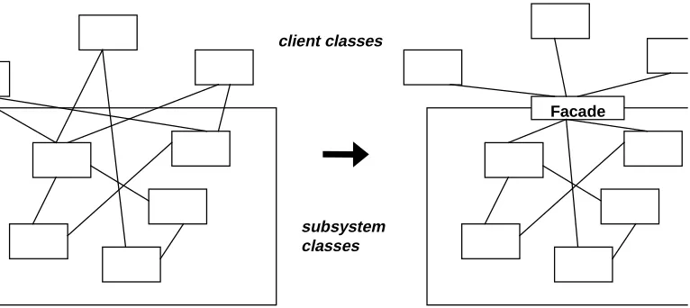
Often in the design of large applications, it is desirable to divide the overall design into a number of subsystems. Reasons for this might be that different subsystems of the application might be implemented by different programmers and to reduce the overall complexity by allowing the designer to (recursively) think of the overall system as that of a number of subsystems. The complexity is reduced by reducing the amount of dependencies and communication between different subsystems. Ideally, this should be minimal as otherwise small changes in one part of the application will ripple through the entire application thereby preventing easy modification of a system.
To overcome this problem, the Facade pattern proposes that a unified interface be implemented to a set of interfaces in a subsystem. In other words, Facade provides a single higher level interface to a subsystem that might contain a number of interfaces. The Facade pattern is illustrated in Figure 1.
Facade client classes
[image:16.595.86.469.385.556.2]subsystem classes
Figure 1 Facade Design Pattern
2.3
Frameworks
2.3.1
Introduction to Frameworks
development of applications in particular domains (eg. Graphical User Interfaces) or business units (eg. manufacturing). In essence, frameworks are one approach to software reuse.
A framework can be defined as a set of cooperating classes that make up a reusable design for a specific class of software. It provides architectural guidance by partitioning the design into abstract classes and defining their responsibilities and collaborations. A developer customises the framework to a particular application by subclassing and composing instances of framework classes [Gam95]. A framework dictates the architecture of an application developed with it. It defines the application’s overall structure, its partitioning into classes and objects, the key responsibilities of those classes and objects, how they collaborate, and the thread of control.
Since a framework is more abstract than a finished application, in order to use a framework to develop a particular application, the developer will need to extend framework classes to implement application specific behaviour.
The objective of developing frameworks is to achieve both design and code reuse, as well as shorter development times for applications, thereby reducing the cost of developing an application. Frameworks leverage the domain knowledge of the framework developers,
thereby leaving the application developer to focus on specific application design issues and problems.
Advantages of using frameworks are the already mentioned code and design reuse, portability, rapid prototyping, and possibly performance customisation [Cam92]. Portability can be achieved through the separation of machine dependent parts of the framework from machine independent parts. Rapid prototyping is achievable because the framework provides code and design reuse, thus making it possible to quickly test various implementations of a particular application built with the framework. Performance customisation can be achieved through the use of one or another framework component depending on the particular application.
2.3.2
Characteristics of Frameworks
Modularity: Because a framework’s potentially unstable implementation details are
encapsulated by a stable interface, applications developed with the framework are not exposed to changes in framework implementation and design, as long as the interface remains stable.
Reusability: Since a framework encapsulates application domain specific knowledge and
prior effort of the framework developer, the application developer is able to reuse common solutions to recurring application requirements, thereby saving development time and improving the quality and reliability of the application.
Extensibility: Frameworks provide hook methods that allow the application developer to
extend the framework where needed.
Inversion of Control: Frameworks generally control the flow of control within an
application via event dispatching patterns. This is also known as the “Hollywood Principle”, or “Don’t call us, we’ll call you”. When events occur, the framework’s dispatcher reacts by invoking hook methods on pre-registered handler objects, which perform application specific processing on the events.
2.3.3
Types of Framework
There are different ways of categorising frameworks. One classification is that of
whitebox versus blackbox frameworks [Joh88]. In a whitebox framework the application
developer adds methods to subclasses of one or more of the framework’s classes. These methods implement application specific behaviour. Since these methods must be designed and implemented as was intended by the designer of the superclasses, the application developer needs to have an understanding of the framework’s implementation.
selection of components, the amount of programming required to create an application with the framework will be much less than to do the same with a whitebox framework. Thus, whitebox frameworks rely on inheritance whereas blackbox frameworks rely on object composition. Of course, there is a continuous range from whitebox to blackbox frameworks with some frameworks using both inheritance and object composition to achieve application creation.
2.3.4
Frameworks in relation to other approaches to reuse
Other approaches to software reuse are design patterns, class libraries, and components [Fay97]. These are related to frameworks in the following ways:
Design Patterns: Both design patterns and frameworks are approaches to software reuse.
However, they differ in a number of ways [Gam95]. Firstly, patterns are more abstract than frameworks. Patterns enable design reuse whereas frameworks allow design and code reuse. Patterns have to be implemented in code every time they are used. Secondly, design patterns are smaller architectural elements than frameworks. This implies that frameworks can contain a number of patterns, but never the other way around. Thirdly, frameworks are specialised to a particular application domain. Design patterns, on the other hand, can be used in any type of application.
Class libraries: Class libraries also are an approach to software reuse. Frameworks
extend the benefits of class libraries in the following ways: Firstly, class libraries generally are less domain specific than frameworks. Generally they are lower level than frameworks and thus don’t offer as high a level of reuse as frameworks. Frameworks, on the other hand, can be viewed as semi-complete applications. Secondly, class libraries don’t exhibit the inversion of control that frameworks do. Frameworks often make use of class libraries. An example is the C++ Standard Template Library.
Components: Yet another approach to reuse, components are self-contained instances of
2.3.5
Examples of Frameworks
Numerous examples of frameworks exist. Here is a brief description of some of them:
Choices is an object-oriented operating system framework implemented in C++. It was
developed at the University of Illinois at Urbana-Champaign [Cam92, Joh91]. The motivation behind the development of Choices was that different users of operating systems have different needs. For example, some applications for operating systems require large virtual address spaces, whereas others, such as real-time embedded systems don’t require virtual memory at all. The Choices framework addresses this problem by providing a family of operating systems that the user can tailor to specific requirements. The Choices framework consists of a number of subframeworks, such as virtual memory,
process management, persistent storage, message passing, and device management. These subframeworks are used to implement subsystems of the operating system. The subframeworks provide abstract classes that are reused through inheritance, making
Choices a whitebox framework.
Smalltalk Model/View/Controller (MVC) is a framework for constructing Smalltalk-80 user interfaces [Gam95]. It consists of three types of object: the Model, the View, and the Controller. The Model is the application object and the View is its screen representation. Each Model can have multiple Views. If the Model’s data changes, the Views are notified to update themselves. The Controller defines how the user interface reacts to user input. An important aspect of MVC is that it contains a number of design patterns, such as Observer, Composite, and Strategy. Thus it demonstrates how design patterns can be used in the development of frameworks. Observer is a pattern that allows a one-to-many dependency between objects to be created so that when one object changes its state, all the other objects are notified and updated automatically. Composite is a pattern that allows a tree-like structure of objects to be created. It allows clients to treat individual objects and compositions of objects in the same way. Strategy is a pattern that allows algorithms to be encapsulated by objects. It allows clients to freely interchange these objects if the algorithm is to be varied. These patterns are described in more detail in [Gam95].
Microsoft’s Microsoft Foundation Classes (MFC) is a framework for the development of
misleading, as it is in fact a framework, though parts of it can be used as a class library. To create a Windows GUI application with MFC, the user needs to subclass from a number of abstract classes. The relationships and constraints between these classes is known as the document-view architecture, similar to the Model and View architecture in MVC. To be able to create any but the most trivial applications, the user needs to have some understanding of these relationships and constraints. Therefore, the MFC could also be classified as a whitebox framework.
2.3.6
Strategies for developing Frameworks
Various methods or strategies for developing frameworks have been proposed. [Bec94] [Dem96] [Kos] [Rob97]. Of these, the method that seems most inclusive of all
framework application domains, and pertains to the entire life cycle of framework development is Evolving Frameworks, a pattern language for framework development. It is described in more detail below.
2.3.6.1
A Pattern Language for developing Frameworks
One strategy, proposed by Roberts and Johnson, for developing frameworks, applies design patterns to the problem of framework development [Rob97]. More specifically, a pattern language for developing object-oriented frameworks is proposed. It is called
Evolving Frameworks. A pattern language can be described as a set of patterns that are
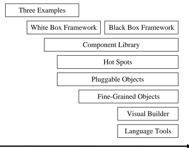
used together to solve a problem. Evolving Frameworks comprises of the following patterns: Three Examples, Whitebox Framework, Blackbox Framework, Component
Library, Hot Spots, Pluggable Objects, Fine-grained Objects, Visual Builder, Language
Tools. The above sequence is the sequence in which the patterns generally will be applied
as the framework evolves, although this is not totally rigid.
Three Examples is the first and fundamental pattern in this pattern language. It argues
that it is impossible to design, from scratch, a framework without first having built at least three applications of the type that the framework is intended to build. The framework abstractions can then be determined from these examples.
inheritance. This framework subsequently could be changed into a Blackbox Framework, but only when it is known which parts of the framework will consistently change across applications and which parts remain constant.
Component Library proposes common classes that should be collected from the
application examples to form a component library.
Hot Spots proposes to separate code which changes between applications from code
which doesn’t. Ideally, the varying code is then encapsulated within objects. This promotes reuse through composition of objects instead of subclassing from other classes. The objective of the Pluggable Objects pattern is to avoid unnecessary subclassing when the subclasses differ only in trivial ways. It achieves this by using parameters in the instance creation protocol. In this way the subclass can be parameterised, in other words, customised for its particular application.
Fine-Grained Objects proposes that objects be broken down into granularities as fine as
possible. The reason for this is that code duplication can be avoided in this way. If objects are not broken down like this, some classes may end up encapsulating multiple behaviours that could possibly vary independently. It is better to replace such a class with a composition that recreates the behaviour of that class.
The creation of Pluggable Objects and Fine-Grained Objects leads to the ability to create applications using composition. Therefore, the next step the design of the framework is to reorganise the framework into a Blackbox Framework, which favours composition over inheritance.
The Visual Builder pattern proposes a graphical program that lets the application developer specify the objects of the application and how they are interconnected.
The last pattern in the language, Language Tools, suggests that specialised inspecting and debugging tools be created for the framework.
Figure 2 shows how the patterns in Evolving Frameworks are related in time. It can be
Three Examples
White Box Framework Black Box Framework
Component Library
Hot Spots
Pluggable Objects
Fine-Grained Objects
Visual Builder
Language Tools
[image:23.595.141.456.91.338.2]Time
Figure 2 Evolving Frameworks
2.3.7
Documenting Frameworks
An approach to documenting frameworks using patterns has been suggested by Johnson
[Joh92]. He proposes that the documentation of a framework has three purposes. Specifically, the framework documentation needs to 1) describe the purpose of the framework, 2) describe how to use the framework, and 3) describe the detailed design of the framework.
The first pattern in the framework documentation describes the purpose of the framework and its application domain. It gives examples of framework applications and introduces the rest of the patterns describing the framework, and which of those patterns should be studied next. This next set of patterns is used to describe how to use the framework. Finally, the detailed design of the framework is described.
2.3.8
Problems regarding Framework Development
Development effort: The effort and domain knowledge required for successful framework
development is higher than that required for application development in a particular domain.
Learning curve: The learning curve involved in learning to use a particular framework is
often quite high. If only a few applications are ever going to be built using a framework, the value of creating such a framework needs to be questioned, since in this case it might not be a cost effective solution. Also, the suitability of a framework to building a particular application may only become apparent after an amount of time has been invested in learning the framework.
Integratability: If applications are built using more than one framework, compatibility
and integration problems may result. Specifically, the inversion of control principle of frameworks could cause problems, as event loops in the frameworks may not be designed to allow interoperability.
Maintainability: As application requirements change frequently, the requirements of
frameworks may change with them. Modifying and adapting a framework may prove difficult for application developers since a deep understanding of framework internals and relationships between framework components is essential.
Validation and defect removal: Debugging applications created with a framework may be
difficult. For example, since the flow of control is controlled by the framework, it may be difficult to step through the application specific code of the application.
Efficiency: The generality and flexibility of a framework may reduce its efficiency.
2.4
CORBA and Frameworks
2.4.1
Introduction to CORBA Object Request Brokers
object applications, which may run in a heterogeneous environment, away from underlying networking protocols and transports. This facility is provided by Object Request Brokers (ORBs), which lie at the heart of the OMA. An ORB allows a client to deliver a request to a target object acting as a server, and it returns any responses to the clients making the requests. The target object may reside in the same process, on the same machine but in a different process, or on a different machine in a different process somewhere on the network. The client-server relationship is only valid on a request basis. A client object for one request could be a server object for another [Vin97].
CORBA consists of the following main elements:
ORB Core: The ORB core lets client objects transparently make requests to server
objects, and receive responses from them, whether they are in-process out-of-process, or remote servers.
Interface Definition Language (IDL): The IDL enables interfaces between client and
server objects to be defined in a declarative, language independent manner. An interface specifies the operations and types that the server object supports.
IDL Client Stub: The client stub acts as a local proxy for a remote server object. It
provides static interfaces to server object’s services. It is created by compiling the
interface definition using an IDL compiler.
IDL Server Skeleton: The server skeleton provides the static interface to each service
exported by the server. Like the client stubs, it is created by compiling the interface definition using an IDL compiler.
Dynamic Invocation Interface (DII): The DII allows the client to discover at runtime the
server interface method to be invoked.
Dynamic Skeleton Invocation (DSI): The DSI is the server equivalent of the DII. It
provides a run-time binding mechanism for servers to handle incoming method calls for components that do not have IDL-based compiled skeletons.
Object Adapter: The Object Adapter serves as the glue between object implementations
and the ORB core.
Interface Repository: The Interface Repository is a database that contains machine
Implementation Repository: The Implementation Repository contains information about
the classes supported by a server, which objects are instantiated, and their IDs.
ORB Interface: The ORB Interface contains APIs to some ORB services that may be
useful to an application.
Inter ORB Protocols: Inter ORB Protocols, such as GIOP and IIOP, allow ORBs from
different vendors to communicate with one another.
2.4.2
Some CORBA Application Scenarios
The objective of developing an ORB framework is to facilitate the implementation of customised ORBs. Customised ORBs are ORBs that are tailored towards one or more particular application scenarios. The following are examples of some such scenarios and
the issues that need to be addressed when developing ORBs, and therefore ORB frameworks, for such scenarios.
2.4.2.1
Reliable Distributed Systems
A distributed system can be considered reliable if its behaviour is predictable despite partial failures, asynchrony, and runtime reconfiguration of the system. Building reliable distributed systems using CORBA is a priority in areas such as electronic commerce, flight reservation systems, and real-time data feeds. It is, however, difficult to achieve for a number of reasons. For example, because of partial failures of the system, the mean time to failure of components in the distributed system decreases as the number of nodes and communication links increases. Complex execution states can lead to situations such as race conditions, deadlocks, and communication failures [Maf97].
Some approaches to implementing reliable distributed systems are message queues, transaction processing monitors, and virtual synchrony. [Maf97] describes how these approaches can be combined into an extended CORBA architecture for reliable systems.
2.4.2.2
Performance in CORBA Distributed Systems
recently, the CORBA specification did not provide definitions for policies or mechanisms for providing QoS guarantees in distributed applications. Recently A/V streams have been added to the CORBA specification.
Existing ORBs exhibit significant runtime throughput and latency overheads. To be able to construct real-time ORBs that can exhibit end to end QoS guarantees, the factors that affect performance of ORBs need to be addressed. Some of these factors are [Sch97]: specification of end to end QoS requirements, operating system and network resource scheduling, communication protocols performance, request demultiplexing and dispatching optimisation, memory management optimisation, and presentation layer conversions.
2.4.2.3
Mobile Distributed Systems
Mobile distributed systems entail some of the following aspects: the frequent movement of users and hosts, the scarcity of network and local computing resources available to the
mobile host, the possibility of disconnections. These lead to the following problems with which mobile distributed systems are faced: frequent disconnections from the network, widely varying bandwidths among wired and wireless links, limited CPU power and device capacity on a mobile host, transient servers due to frequent handoff.
These problems lead to the following design guidelines for mobile distributed systems [Che97]:
Minimum host-network coupling: Applications should be designed with minimum
coupling between the mobile host and the server as connections generally are unreliable.
Connection transparency: An application should be able to continue operating
transparently even if there are changes in the connection between mobile host and server, such as handoff and disconnections.
Indirect interaction: To minimise interaction over the wireless link, user input processing
should be performed as close to the mobile host as possible.
Adaptive communication protocols: Because of variable bandwidth and heterogeneous
networks, communication protocols need to be adaptable.
Application partitioning: Because of unreliable connections, applications need to be
2.4.2.4
Developing a Framework for Customisable ORBs
The previous sections have introduced a number of topics which are fundamental to the project, the development of a framework for customisable ORBs. The content of these sections is to serve only as an introduction to some of the issues and approaches which are relevant to this project.
The suggested approach to developing the framework is to apply the pattern language
Evolving Frameworks mentioned in the frameworks section. This pattern language begins
with the Three Examples pattern. Considering the limited amount of time allocated to this project, it would obviously not be feasible to implement three separate ORBs, which may cover various application scenarios, as is suggested by that pattern. On the other hand, a deep, hands-on understanding of the application domain, customisable ORBs, is required in order to attempt the design and implementation of an ORB framework. A possible approach to overcome this problem would be to examine the implementations of a
number of different existing ORBs. ORBs exist for which the source code is publicly available, and some of these are also well documented from a design point of view. Some CORBA ORB implementations which focus on some of the different application scenarios described above and for which source code is available are TAO, Electra, and
OmniORB.
OmniORB is a CORBA compliant ORB that has been developed by the Olivetti and Oracle Research Laboratory. It is a plain, “vanilla” ORB, not geared towards any particular application domain.
TAO is a CORBA compliant ORB that has been developed at the Department of
Computer Science, Washington University. It is an ORB aimed at applications with real-time QoS requirements. It is designed to be extensible, maintainable, and dynamically configurable. To achieve these objectives its design relies heavily on the use of design patterns. Its design is well documented using these patterns in [Sch98].
Electra is a CORBA compliant ORB that is geared towards fault-tolerance and group
The first step will be to study the implementations of these three ORBs. This would involve the study of both any documentation and literature that is available about them, and also the source code which is publicly available. For the latter, an object-oriented browsing tool, such as Takefive Software’s Sniff+, might be useful. Some of these tools provide the ability to ‘reverse engineer’ source code to object notation, such as UML.
2.5
Summary
Chapter 3
Analysis of existing Object Request
Brokers
3.1
Introduction
This chapter describes an analysis of three publicly available CORBA compliant ORBs. The three ORBs are OmniORB, TAO, and Electra. OmniORB was developed by the Olivetti and Oracle Research Laboratory. It is a basic ORB which is not geared towards any particular application domain. TAO was developed at the Department of Computer Science, Washington University. It is aimed at applications with real-time Quality of Service requirements. Electra was developed by Silvano Maffeis while at the University of Zurich. It is an ORB that is geared towards fault-tolerance and group communication. It allows object groups, reliable multicast communication, and object replication.
3.2
OmniORB
3.2.1
Introduction
(http://www.orl.co.uk). This section documents the investigation into the
implementation of OmniORB2.
3.2.2
Purpose of the analysis
The purpose of the analysis of the implementation of OmniORB2 was to gain insight into how the architecture of a typical ORB is structured. Specifically, the internals of
OmniORB2 were to be analysed, in other words, those parts of OmniORB2 that implement the CORBA specification but that are left to be implemented by the different ORB vendors. Especially interesting was to determine whether any design patterns were used. The use of these would facilitate the understanding of the design of OmniORB2 and would be helpful in the subsequent design of an ORB framework. They would also make it easier to document the design of OmniORB2.
3.2.3
Main features of OmniORB2
3.2.3.1
CORBA 2 compliancy
As stated in the introduction, OmniORB2 is an ORB that implements version 2.0 of the OMG’s CORBA specification. It implements the Internet Inter-ORB Protocol
(IIOP) and uses this to communicate with other ORBs, and also uses it as its own native protocol, i.e. for the communication between its objects residing in different address spaces.
3.2.3.2
Platform support
OmniORB2 supports the following platforms: Sun Solaris, Digital Unix, HPUX, IBM AIX, Linux, Windows NT, Windows 95, OpenVMS, ATMos, NextStep. Extensive use of preprocessor directives is made in the source code to allow compilation for these numerous supported platforms. This can make the source code quite difficult to understand at times.
3.2.3.3
Missing features
• OmniORB2’s Basic Object Adapter (BOA) does not support dynamic server activation and deactivation policies. It only supports the persistent server activation policy.
• The Dynamic Invocation Interface is not supported.
• The Dynamic Skeleton Interface is not supported.
• OmniORB2 does not have its own Interface Repository.
3.2.4
Building and testing OmniORB2
The OmniORB2 distribution was downloaded from the Oracle & Olivetti Research Laboratory’s web site. Although ready to run binaries are available to download, OmniORB2 was downloaded in source code form and compiled and linked on site.
The download package comes as a zipped tar file which extracts into a directory tree. The main parts of the package are:
3.2.4.1
The documentation
This consists of four documents which address the OmniORB2 itself, the OmniNames naming service, which is an OmniORB2 implementation of the OMG’s COS Naming Service Specification, OmniThread, which is a portable thread abstraction library used by OmniORB2, and OmniORB utilities.
Of these documents, the principal one is the OmniORB2 manual. It is addressed at the application developer who wants to know how to get started using OmniORB2. Some of the examples that are provided with OmniORB2 are explained. The OmniORB2 API is explained as is the interface to the Basic Object Adapter (BOA). However, the internal architecture of the ORB is not documented.
3.2.4.2
The source code
Source code is provided for OmniORB2 itself, the OmniThread library, the OmniIDL2 compiler, which is the IDL compiler supplied with OmniORB2, a number of examples, the OmniNames naming service, and the OmniORB2 utilities.
3.2.4.3
Makefiles
3.2.4.4
Tools and methods used for analysing OmniORB
Initially OmniORB2 was built using the Sun C++ compiler and GNUmake under Solaris 2.6. The three Echo examples, which are documented in Chapter 1 of the OmniORB2 manual, were also built and executed as indicated. Because of a lack of suitable debugging, analysis, and browsing tools under Unix, the OmniORB2 binaries were rebuilt under Windows NT using Microsoft Visual C++ 5.0 and the Cygnus Solutions gnu-win32 utilities. The advantage of examining OmniORB2 under Windows NT was that the debugger which is supplied with Visual C++ could be used to step through the application and ORB source code as an application was being executed.
Next, the OmniORB2 source code was analysed using SNIFF+, a cross-platform programming environment by TakeFive Software. SNIFF+ provides a number of features that aid the comprehension of existing source code. Numerous tools, such as an inheritance hierarchy browser, a cross reference browser, and an include browser, are part of this environment and were found to be useful in the understanding of the implementation of OmniORB2. SNIFF+ includes its own source code parser which parses the source code of a project and builds its own internal representation of it. A project therefore does not need to be compiled before the SNIFF+ tools can be used.
3.2.4.5
Problems encountered
Some problems were encountered in trying to analyse the architecture of OmniORB2. Initially Solaris 5.6 was used as a platform for building the ORB and sample applications. It was found that because of a lack of suitable tools it would prove difficult to easily study the implementation of the ORB. The ORB was rebuilt under Windows NT and this was found to be advantageous, especially in the area of debugging.
A principal difficulty was the size of the source code. In the entire source code there are over 360 classes and structures, not including nested classes. The source code is very sparsely commented. There are no documents explaining the OmniORB2 architecture.
A problem noted with SNIFF+ is that it ignores nested classes, ie. those classes that are declared within other class declarations. This meant that nested classes could not be browsed as easily as others, but it was found not to be a big problem.
3.2.5
Overall architecture of the ORB
The following sections describe some of the principal components of the OmniORB2 ORB. C++ namespace is not used. Instead, some classes are nested within other classes, for example, the class ORB is nested within the CORBA class, thus becoming CORBA::ORB. The reason for this is that some of the supported compilers may not
have implemented the namespace keyword.
3.2.5.1
The ORB
The class that represents the ORB is CORBA::ORB. It provides the C++ mapping of the CORBA::ORB interface. It also provides some internal OmniORB2 specific
functionality. An instance of this class is created in the function CORBA::ORB_init(…) unless an instance of it already exists. This function is called by both the object implementation and the client in order to obtain a pointer to the ORB.
Another class, omniORB, provides the public API of OmniORB2’s extension to CORBA. This API is intended to be used in application code. All its members and methods are declared static and no actual instance of omniORB is ever created. The public API provides features such as run-time tracing and diagnostic messages, limiting the GIOP message size, and trapping internal errors.
3.2.5.2
The BOA
The class that represents the BOA is CORBA::BOA. It provides the C++ mapping of the CORBA::BOA interface. Again, it also provides some internal OmniORB2 specific functionality. An instance of this class is created in the function
CORBA::ORB::BOA_init unless an instance of it already exists. As with the function creating the ORB, this function is called by both the object implementation and client in order to obtain a pointer to the BOA. After a call to BOA_init, the BOA must be activated using impl_is_ready. This starts a thread listening on the
skeleton class and is called after the object is fully initialised. In the example below, it is a member function of the class _sk_Echo.
3.2.5.3
Sample skeleton code generated by the IDL compiler
This section describes which classes are created by the IDL compiler when a sample IDL file is compiled.
If the following example IDL interface
interface Echo {
string echoString (in string mesg);
}
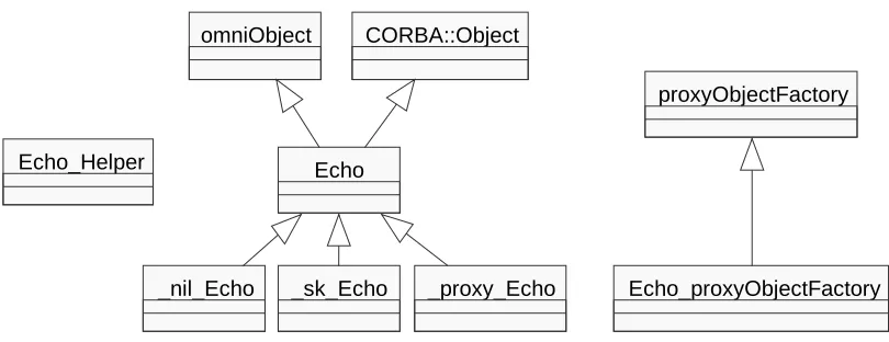
is compiled using the OmniORB2 IDL compiler, a number of classes are created by the IDL compiler. They are: Echo, _nil_Echo, _sk_Echo, _proxy_Echo, Echo_proxyObjectFactory, and Echo_Helper. Their relationships are
shown in Figure 3.
Echo: A pointer to this class is the object reference that corresponds to the Echo
interface.
_nil_Echo: This class provides a nil object reference of the Echo interface.
_sk_Echo: This is the skeleton class used for implementing the Echo
[image:35.595.98.503.531.687.2]implementation object. To implement an Echo object, a class is derived from _sk_Echo.
Figure 3 OmniORB Stub and Skeleton Classes
_proxy_Echo: An instance of _proxy_Echo is created as a local representation
omniObject
Echo
_nil_Echo _sk_Echo _proxy_Echo CORBA::Object
Echo_Helper
proxyObjectFactory
Echo_proxyObjectFactory: An instance of this class creates the
_proxy_Echo object on the client side if the Echo implementation resides in a
different address space.
3.2.5.4
The OmniThread library
[image:36.595.132.450.265.299.2]The purpose of the Omni Thread library is to provide a common set of thread operations for OmniORB2. Porting between different platforms with different thread interfaces is facilitated through this layer.
Figure 4 OmniORB Omni Thread Library Classes
The interface to the Omni Thread library is designed to be similar to that of POSIX threads. Essentially, the Omni Thread library consists of wrapper classes around thread calls. There are four principal classes in the Omni Thread library: omni_condition, omni_mutex, omni_semaphore, and omni_thread.
Depending on the platform, different implementations of these wrapper classes are conditionally compiled. The Omni Thread library is illustrated in Figure 4.
3.2.5.5
Implementation of GIOP and IIOP
The Rope and Strand classes
OmniORB2’s underlying GIOP communications mechanism is built on the concept of Rope and Strand classes.
Figure 5 OmniORB Rope Inheritance Hierarchy
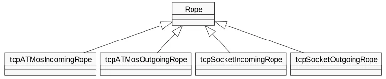
The Rope class represents a bidirectional buffered stream that connects two address spaces. The connection point of each address space is identified by an object of type Endpoint. A Rope object is composed of one or more objects of type Strand.
Rope
tcpATMosIncomingRope tcpATMosOutgoingRope tcpSocketIncomingRope tcpSocketOutgoingRope
[image:36.595.108.506.587.669.2]Each Strand object represents a transport dependent connection. All Strand objects of the same Rope object can be used interchangeably for the sending and receiving of messages between the two connected address spaces identified by the
Endpoint objects. The Rope inheritance hierarchy is shown in Figure 5.
The Rope class is an abstract base class that defines the interface for the derived rope classes. Depending on the transport implementation, Rope objects are instantiated as tcpSocket ropes or tcpATMos ropes. They can be of the incoming or outgoing variety. Incoming Rope objects are used by the BOA to receive requests and dispatch them to the object. Outgoing Rope objects are used by the ORB to send requests. The instantiation of Rope objects is performed by objects derived from the abstract base class ropeFactory. Its inheritance hierarchy is shown in Figure 6. These classes represent an implementation of the Abstract Factory design pattern.
Figure 6 OmniORB Rope Factory Inheritance Hierarchy
An Abstract Factory can be used when related objects, in this case objects of type Rope, need to be created without specifying their concrete classes, for example
tcpATMosIncomingRope or tcpSocketIncomingRope.
The Strand inheritance hierarchy is shown in Figure 7. For example, a tcpSocketIncomingRope object would contain a number of
tcpSocketStrand objects.
ropeFactory
incomingRopeFactory outgoingRopeFactory
tcpATMosMTincomingFactory tcpSocketMTincomingFactory tcpATMosMToutgoingFactory tcpSocketMToutgoingFactory
Strand
Figure 7 OmniORB Strand Inheritance Hierarchy
The Endpoint inheritance hierarchy is shown in Figure 8.
Figure 8 OmniORB Endpoint Inheritance Hierarchy
The GIOP driver classes
The GIOP_C and GIOP_S classes are built on top of a strand. They implement the General Inter-ORB Protocol (GIOP). The GIOP protocol is asymmetric. GIOP_C provides the functions to drive the client side protocol. GIOP_S provides the server side functions. The GIOP_C and GIOP_S inheritance hierarchy is shown in Figure 9.
Endpoint
tcpATMosEndpoint tcpSocketEndpoint
Sync
Figure 9 OmniORB GIOP Inheritance Hierarchy
An object of the Sync class is used to provide exclusive access to a Strand object. A number of Sync objects can be associated with any particular Strand object. Derived from Sync is the class NetBufferedStream. This class provides the marshalling functionality for different CORBA data types. In other words, this class provides the functionality to load and unload the buffer that is used for transmitting and receiving using the Strand object associated with the Sync object. The marshalling is totally independent of the transport layer that is used.. The Sync class only refers to Strand and Rope types, but not their concrete subclasses. The MemBufferedStream class has similar functionality to the
NetBufferedStream class except that it is used when the client and server reside
in the same address space and the transport layer and layers below it can be bypassed. The GIOP_Basetypes class defines some types, such as message header types, that are common to both GIOP_C and GIOP_S. Calling the constructor of GIOP_C or GIOP_S automatically aquires a Strand object.
A GIOP_C object can be in a number of states, such as Idle, RequestInProgress, WaitingForReply, ReplyIsBeingProcessed,
and Zombie. Similarly, a GIOP_S object can be in the states Idle,
RequestIsBeingProcessed, WaitingForReply,
ReplyIsBeingComposed, and Zombie.
Threading models used in OmniORB2
The threading model used to dispatch incoming requests is determined by the classes derived from ropeFactory. It is described in the section below.
Threading model to service incoming requests
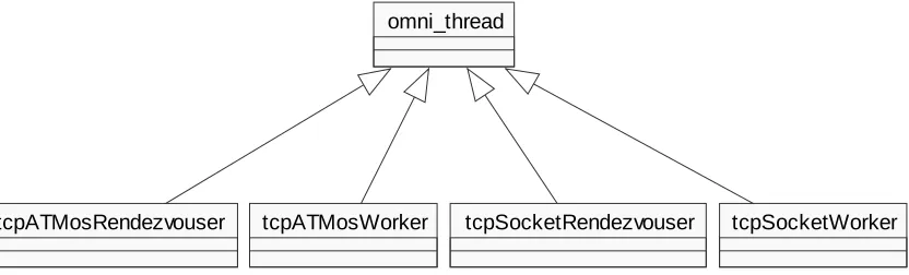
A number of thread classes inherit from omni_thread. Two types of class that inherit from omni_thread are the tcpRendezvouser and the tcpWorker variety of class. These come in Socket and ATMos varieties. A worker class, for example tcpSocketWorker, is associated with each incoming Rope object’s Strand
object. When an incoming object derived from Rope is created, a tcpRendezvouser thread is created and started. This thread is associated with that particular Rope object. For example, a tcpSocketRendezvouser is created and started when a tcpSocketIncomingRope is created. The tcpSocketRendezvouser thread
will wait for incoming connection requests using the accept system call. If a request is received, a new Strand, in this case a tcpSocketStrand, will be created and a tcpWorker, in this case a tcpSocketWorker, will be created and started. The worker will be associated with the particular Strand object. For as long as there are incoming requests on a particular Strand, for each request a GIOP_S object is instantiated by the worker. This GIOP_S object will gain exclusive access to the Strand object and will unmarshal and dispatch the request. When the request has
[image:40.595.95.511.497.623.2]been dispatched or otherwise handled, the GIOP_S object will be deleted. The process is repeated for the next request on that Strand object.
Figure 10 OmniORB Worker And Rendezvouser Inheritance Hierarchy
A scavenger thread periodically scans all the Strand objects. If it detects that a Strand object has been idle for a certain period it may shut it down, i.e. delete the
Strand object and stop the associated worker thread. The Worker and Rendezvouser
inheritance hierarchy is illustrated in Figure 10.
omni_thread
3.2.6
Conclusion
With some initial delays in setting up OmniORB2 and the relatively brief period allocated to its study, it was found that only an overall view of the internals of OmniORB2 could be obtained and that most areas could not be studied in great detail. However, the study has been useful in that it has provided a general insight into the workings of an ORB and that it offers areas of interest, for example, the implementation of certain classes, to be revisited and studied in greater detail at a later stage of the project, if necessary.
3.3
TAO
3.3.1
Introduction
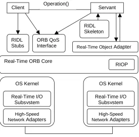
In the study of the implementation of a number of CORBA compliant public domain ORBs, TAO (The ACE ORB) was chosen to be the second ORB to be examined. TAO is a CORBA 2.0 compliant ORB, aimed at high-performance, real-time applications. It extends the OMG CORBA specification by allowing applications to specify Quality of Service (QoS) requirements. It was developed by the Distributed
Object Computing Group at Washington University (www.cs.wustl.edu/~schmidt/TAO.html). This report documents the
investigation into the implementation of TAO.
3.3.2
Purpose of the analysis
The purpose of the analysis of the implementation of TAO was similar to that of OmniORB2. In addition, an objective of the study was to gain insight into how an ORB aimed at the high-performance, realtime application domain might be implemented, and how it would differ from a standard ORB.
3.3.3.1
Realtime ORB core
TAO’s realtime ORB core is based on the Adaptive Communication Environment (ACE) framework. It is designed to provide a number of threading models, such as thread-per-connection, or reactor-per-thread-priority. The TAO ORB core uses the Realtime Inter ORB Protocol (RIOP), which is based on IIOP, for interORB communication.
3.3.3.2
Optimised Object Adapter
The TAO Object Adapter is responsible for demultiplexing and dispatching client requests to servant operations. In conventional ORB systems, demultiplexing takes place on a number of layers. TAO’s Object Adapter uses demultiplexing keys assigned by the ORB to clients to achieve delayered demultiplexing.
3.3.3.3
Realtime IDL (RIDL) QoS specification
TAO provides an IDL interface for applicatins to specify their realtime resource requirements. This information is passed to TAO’s Realtime Scheduling Service. The TAO Realtime Scheduling Service performs offline feasability scheduling analysis to determine whether there are enough CPU resources to perform all requested tasks which the application has registered with the Realtime Scheduling Service repository. The Scheduling Services also perform thread priority assignment during this offline analysis. This information is used by the ORB core at runtime to assign thread priorities. At runtime, requests are queued according to their priorities.
3.3.3.4
IDL compiler optimisations
Because the conversion of typed operation parameters from higher-level to lower-level representations (marshaling) and vice versa (demarshaling) can be a bottleneck, the TAO IDL compiler provides a number of optimising features. For example, either interpreted or compiled IDL stubs and skeletons can be linked into the application. Interpreted code is slower, but smaller in size, whereas compiled code is faster, but bigger in size.
For efficiency reasons, TAO tries to keep dynamic memory management to a minimum. For example, it uses a “zero-copy” buffer management system when sending and receiving client requests to and from the network.
3.3.3.6
Platform support
Platforms supported by TAO are Windows NT, Solaris, VxWorks, and Linux.
3.3.4
Building and testing TAO
The TAO distribution kit was downloaded from the TAO website. It includes the ACE framework distribution. Uncompressed, the package is about 40MB in size. Both ACE and TAO were built from the source code using GNUmake and the Sun C++ compiler under Solaris 2.6.
3.3.4.1
The documentation
The design of both ACE and TAO is very well documented. A number of papers exist, outlining the design of ACE and TAO, patterns used in their design, and performance measurements and comparisons with a number of other ORBs. Most of the information about the design of TAO was obtained from these papers. They can be downloaded from the TAO website.
3.3.5
Overall Architecture of the TAO ORB
TAO is a CORBA compliant Object Request Broker that is aimed at real time distributed applications. It is designed to deliver end-to-end Quality of Service (QoS) guarantees. QoS guarantees allow applications to meet certain timing constraints, which, if they weren’t met, would render useless the application built on top of the ORB.
3.3.5.1
The ACE Framework
concurrency. The ACE framework also provides instances of a number of design patterns, such as Reactor and Acceptor-Connector, which recur in object oriented network and communication applications. These patterns will be described in a later
section.
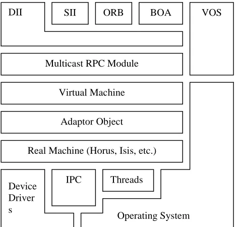
Layers in the ACE Framework
The ACE framework consists of a number of layers as depicted in Figure 11.
Figure 11 ACE Framework Layers
The ACE OS Adaptation Layer
The ACE OS Adaptation Layer forms an interface to the upper ACE layers for the following platform specific OS mechanisms:
• multithreading and synchronisation
• interprocess communication
• event demultiplexing
• explicit dynamic linking
• memory mapped files and shared memory
The ACE OO Wrappers Layer
The ACE OO Wrappers Layer provides C++ classes that encapsulate the various OS mechanisms in the Adaptation Layer. The wrapper class categories include:
IPC mechanisms
IPC mechanisms such as sockets, TLI, Named Pipes, and STREAM pipes. The wrapper classes in this category all inherit from the abstract base class IPC_SAP
(Interprocess Communication Service Access Point) as depicted in
Figure 12.
ACE Network Service Components ACE Framework
Figure 12 ACE IPC Class Hierarchy
Service Initialisation
Related to the IPC mechanisms are the Accptor-Connector classes which implement the design pattern of the same name. This pattern is used for the implementation of service initialisation in communication software. It decouples the initialisation of a communication service from the tasks the service performs once it is up and running and initialisation has been completed.
Concurrency Mechanisms
Concurrency mechanisms such as mutexes, threads, and semaphores are abstracted through C++ classes. These are illustrated in Figure 13. Thread mechanisms include
Solaris threads, POSIX Pthreads and Win32 threads.
Figure 13 ACE Classes For Concurrency
Memory Management Mechanisms
These provide an abstraction for the dynamic management, ie. allocation and deallocation, of shared and local memory.
This category of wrapper classes provides an encapsulation of OS event
demultiplexing calls such as select, poll, and (Win32’s)
WaitForMultipleObjects.
The ACE Framework Layer
This layer builds on the lower two layers, described above, by instantiating a number of design patterns that can be used in the development of network applications. These patterns include Reactor and Service Configurator. They are described below.
The ACE Network Service Components Layer
This layer provides a number of network service components that are constructed using the components of the lower layers. Examples of the network services provided by this layer are logging, naming, locking, and time synchronisation services. The components of this layer also illustrate how to construct services and applications using the classes provided by the lower layers.
3.3.5.2
Design Patterns in ACE
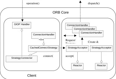
The Acceptor-Connector Design Pattern
The Acceptor performs passive connection establishment, while the Connector
performs active connection establishment. The participants of this pattern are shown in Figure 14.
Figure 14 Acceptor Connector Design Pattern
Each ServiceHandler contains a transport endpoint. This endpoint might, for
example, be a socket descriptor. A ServiceHandler on the client side is used to
exchange data with its corresponding service handler on the server side, and vice versa. An Acceptor is a factory that creates a ServiceHandler and initialises it.
It is used for passively establishing a connection. It will listen on its
peer_acceptor endpoint. When a connection request is received, it will invoke its
accept method which will create a new ServiceHandler to handle that
connection. The Acceptor will then again wait for new connection requests on its
peer_acceptor endpoint. The Connector is used to actively set up a
connection. The Connector’s connect method will establish a connection with a
remote Acceptor. It also initialises a ServiceHandler which will handle the
new connection.
The Dispatcher demultiplexes connection requests that may be received for
different Acceptors. It will pass the requests to the appropriate Acceptor. This
allows a number of different Acceptors to wait for connection establishment
requests. The Dispatcher can be implemented using the Reactor design pattern
which is described below. The Dispatcher is also used on the Connector side to
complete the establishment of connections that were initiated asynchronously, using
connect. It is not needed if connections were initiated synchronously by the
Connector since the thread of control that calls connect will also call
complete, which completes connection establishment.
The Reactor Design Pattern
The Reactor (also known as Dispatcher) design pattern is used to demultiplex requests that are sent to an application by any number of clients. Each request may be
for a particular service. Different services are represented by different EventHandlers. Each of these EventHandlers is responsible for dispatching its
service requests, ie passing the request to the actual service. The structure of this pattern is given in Figure 15.
InitiationDispatcher handle_events() register_handler() remove_handler()
select(handlers);
foreach h in handlers loop h.handle_event(type) end loop
Figure 15 Reactor Design Pattern
A Handle represents an OS resource, such as a network connection. The
SynchronousEventDemultiplexer waits for events to occur on a set of
handles. When an event can be handled without blocking, it returns. This class is
essentially a wrapper for an event demultiplexing function, such as select under
Unix. The InitiationDispatcher is the central class in this pattern. It allows
EventHandlers to be registered with it and removed from it. When the
SynchronousEventDemultiplexer detects a new event occuring, it triggers
the InitiationDispatcher to call the relevant application specific concrete
EventHandler.
The Service Configurator Design Pattern
The Service Configurator design pattern is used to implement explicit dynamic linking. Dynamic linking allows the addition and deletion of object files into the address space of a process either at program startup or during program run-time. Dynamic linking is supported by various operating systems, such as SunOS 4.x, 5.x, and Windows NT.
The ServiceObject represents the interface to a dynamically linkable service. Its inheritance hierarchy is shown in Figure 16.
Figure 16 Service Object Inheritance Hierarchy
The SharedObject abstract base class provides an interface for dynamically
linking service handler objects. The SharedObject abstract base class is kept
separate from the EventHandler abstract base class since certain services may
require dynamic linking, event demultiplexing, or both. Concrete subclasses of ServiceObject are used to implement application specific functionality of the service that can be configured by the Service Configurator.
ServiceObjects are managed by the ServiceRepository class. This class is
an