Abstract— The inertial continuously variable transmission is a mechanical transmission which is based on the principle of inertia. This transmission has a lot of advantages, namely: compactness, minimum friction losses and high efficiency as a result of the relatively small number of rotating components, a wide range of transformation of the torque. It does not need any conventional friction clutches. This transmission protects the engine from overload when the output shaft is braked. This drive guarantees optimum conditions of work for the engine regardless of the changing of load, and smoothly changes output speed according to the load. Mostly, design of this transmission consists of a pulsed mechanism with unbalanced inertial units and two overrunning clutches. The objects of the investigation are structural dynamic analysis of the continuously variable transmission. The physical and mathematical models of this transmission are developed. Dynamics of the transmissions is described by systems of substantial nonlinear differential equations. In general, precise methods of solution for such equations do not exist. Therefore, in practice, approximate analytical and numerical methods must be employed. Each approach has its advantages and disadvantages. Besides, the nonlinear differential equations were solved on the basis of Runge-Kutta numerical method. In this paper, a new design of the inertial transmission with only one overrunning clutch is suggested. This transmission provides a high level of the load ability. Besides, the periodic solutions of the equations were also received by means of the numerical methods. Optimal working modes of the transmission were found using these periodical solutions.
Index Terms— Inertia transmission, dynamics, vibrations, external characteristics
I. INTRODUCTION
HE inertial continuously variable transmission is a mechanical transmission which is based on the principle of inertia [1]. This transmission has a lot of advantages: compactness, minimum friction losses, high efficiency, and wide range of the torque transformation. It does not need any conventional friction clutches. This transmission protects the engine from overload when output shaft is stopped. This drive guarantees optimum
Manuscript received July 23, 2017. The work was supported by Act 211 Government of the Russian Federation, contract № 02.A03.21.
S. V. Aliukov is with the South Ural State University, 76 Prospekt Lenina, Chelyabinsk, 454080, Russian Federation (corresponding author, home phone: +7-351-267-97-81; sell phone: 8-922-6350-198; e-mail: [email protected]).
A. V. Keller is with the South Ural State University, 76 Prospekt Lenina, Chelyabinsk, 454080, Russian Federation (e-mail: [email protected]).
A. S. Alyukov is with the South Ural State University, 76 Prospekt Lenina, Chelyabinsk, 454080, Russian Federation, sell phone: +79000716743; e-mail: [email protected]).
conditions of work for the engine regardless of the changing of load, and smoothly changes output speed with change the load. However, despite of these advantages, the inertial continuously variable transmissions are not widely used in the automotive industry. The main reason for this is that in the design of the transmissions there are two overrunning clutches which are characterized by low reliability under severe operating conditions: high dynamic loads and high on and off power frequency.
The purpose of the paper is the increase the load ability of the continuously variable transmission by reducing the number of the overrunningclutches.
II. THE PHYSICAL MODEL OF THE CONTINUOUSLY
VARIABLE TRANSMISSION
In general, the inertial continuously variable transmission contains the pulsed mechanism with unbalanced inertial elements, for example, planetary gear with unbalanced satellites, and two overrunning clutches. The main purpose of the pulsed mechanism is to create alternative-sign impulses of the torque. One of the overrunning clutches (the output overrunning clutch) transmits direct impulses of the torque to the output shaft, the other one (the body overrunning clutch) transmits the reverse impulse of the torque on the body of the transmission. The presence of two overrunning clutches determines the possible way for increasing of the reliability of the transmission by reducing the number of the overrunning clutches. For example, the well-known Hobbs’ inertial transmission [1] has only the body overrunning clutch. In this transmission design, there is no the output overrunning clutch and the output shaft of the pulsed mechanism is directly connected with the driven shaft of the transmission. This design is characterized by a high level of irregular rotation of the driven shaft, because the output shaft of the pulsed mechanism rigidly connected with the driven shaft of the transmission. It leads to irregular rotation of the driven shaft of the transmission.
In this paper, the design of the inertial continuously variable transmission without the body overrunning clutch is suggested. In the design solution, the output shaft of the pulsed mechanism is connected with the body of transmission, not through the overrunning clutch, but through an elastic element in the circumferential direction. A spring or a torsion shaft can be used as elastic element. The scheme of such a transmission is shown in Figure 1. Here, 1 is the drive shaft of the transmission, 2 are unbalanced loading elements, 3 is the output shaft (the reactor) of the pulsed mechanism, 4 is the elastic element, 5 is the output overrunning clutch, and 6 is the output shaft
Vibrations and Properties of Inertia
Continuously Variable Transmissions
S. Aliukov, A. Keller, and A. Alyukov
of the transmission. The elastic link is shown schematically and this link determines the connection of the output shaft of the pulsed mechanism with the body of the transmission, not in the radial direction, but in circumferential one.
Fig. 1. Kinematic scheme of the inertial continuously variable transmission with high load ability
The principle of operation of the proposed transmission is as follows.
While the driving shaft 1 is rotating, the unbalanced loading elements 2 provide alternative-sign impulses of the torque acting on the output shaft 3 of the pulsed mechanism. Because the output shaft 3 is connected with the body of the transmission by means of the elastic link 4, the shaft performs alternating vibration. The elastic link accumulates the potential energy during the reverse impulse of the torque and transfers the energy during direct rotation of the shaft 3 on the output shaft 6. Such kind of the design of the inertial transmission allows using only one overrunning clutch, such as in Hobbs’ transmission. In contrast to Hobbs’ transmission, the suggested design provides high equability of the rotation of the driven shaft 6. In this case, the output shaft 3 of the pulsed mechanism is not rigid connected with the driven shaft 6 of the transmission. Transfer of the motion is occurred through the output overrunning clutch. The driven shaft 6 of the transmission has the ability for independent rotation. Figure 2 illustrates the pulsed mechanism.
It is important to note, the replacement of the body overrunning clutch by means of the elastic link not only reduces the number of overrunning clutches but also reduces the peak load on the output overrunning clutch. The reduction of the load is due to the accumulation of the potential energy in the elastic link 4 during the reverse impulse of the torque. For example, let consider the mode of the operation of the transmission when the driven shaft 6 of the transmission is stopped. This mode is the most loaded mode of the operation of the transmission. Average values of the torque acting on the driven shaft in the usual rigid design of the inertial transmission and the suggested transmission with the elastic link are defined by the expressions, respectively
0
sin
2 ;
πср
M
A
xdx
A
2
0
(1 sin )
2
,
πср
М
В
x dx
πB
where,
A
andB
are coefficients depending on the parameters of the pulsed mechanism. Matching the average values, we obtainB
A/π
. It is easy to determine that the maximum value of the torque acting on the driven shaft of the transmission in the second case decreases inπ
/
2
[image:2.595.347.512.172.423.2]times.
Fig. 2. Pulsed mechanism
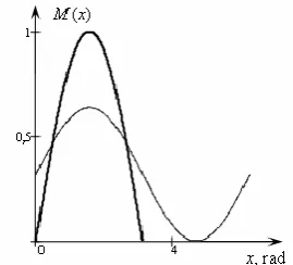
The above example is illustrated by Figure 3. Here, the thick line shows the graph of the torque acting on the driven shaft in the usual rigid design of the inertial transmission; the thin line is for the suggested transmission.
Fig. 3. Graphs of torques acting on the driven shaft
[image:2.595.359.494.521.643.2]III. THE MATHEMATICAL MODEL OF THE CONTINUOUSLY
VARIABLE TRANSMISSION
The mathematical model of the inertial continuously variable transmission is based on Lagrange equations of the second kind.
Note, that the inertial transmission is a system of variable structure. The values of some of its physical parameters vary abruptly during the transmission’s operating cycle and are described by piecewise linear functions. Therefore, in formulating the mathematical model, the differential equations of motion of the transmission are constructed in sections (intervals). For the transmission we consider the following sections: 1) the section of the separated motion of the output shaft of the pulsed mechanism and the driven shaft of the transmission; 2) the section of their joint motion. In each section the motion of the transmission is described by means of its own systems of differential equations. Besides, while we construct the differential equations, the dynamic characteristic of the drive engine [3] is taken into account.
As the generalized coordinates, we take the angle
of rotation of the driving shaft 1, the angle
of rotation of the output shaft 2 of the pulsed mechanism, and the angle
of the driven shaft 6.In the section of the separated motion of the output shaft of the pulsed mechanism and the driven shaft of the transmission, the system of differential equations takes the form
2 2
1 2 4 6
2 2
2 3 5 6
4
(
)
,
(
)
0,
,
1
(
),
D C ДD Н Н
Х
A
A
A
A
M
A
A
A
A
с
J
M
M
М
Т М
(1) where,
, sin , cos 2 , cos 2 , cos 2 4 3 2 2 2 3 3 2 3 2 2 1 1 q q k a nmah A q k b nmbh nJ q k b nmb J A q a b k ab nmh nJ q k b q k a nmab A q k a nmah nJ q k a nma J A 5 6 sin , sin , ( ), , bА nmbh q q
k
A nmkhq
q
k a b
4 2 1,J ,J
J are the moments of inertia of the driving shaft, the output shaft of the pulsed mechanism, and the driven shaft of the transmission, respectively,
3
nJ is the total moment of inertia of the unbalanced elements relative to the geometric center,
nm is the total mass of the unbalanced elements,
h is the distance between the geometric center and the center of mass of the unbalanced elements,
, ,
a b q are parameters of the pulsed mechanism,
с
is the angular stiffness of the elastic link,С
М is the drag torque acting on the driven shaft of the transmission,
D
M is the engine torque acting on the drive shaft,
Н
M is the rated torque of the engine,
Н Х
, are the angular ideal idling and nominal velocities, respectively,Т
is the electromagnetic constant of time of the engine,
is the slope coefficient of the static characteristic.In the section of the joint motion of the output shaft of the pulsed mechanism and the driven shaft of the transmission, the system of differential equations takes the form
2 2
1 2 4 6
2 2
2 3 4 5 6
( ) , ( ) ( ) , , 1 ( ). D C Д
D Н Н
Х
A A A A M
A A J A A с M
M М Т М
(2)
We assume that the speed of the driving shaft is constant
const
[4]. This is acceptable because the moment of inertia of the driving component is usually much greater than the moments of inertia of the inertial transmission’s other components. The driving component acts as a flywheel stabilizing its speed.Assuming constant speed of the driving shaft, we may simplify the mathematical model of the transmission and reduce the order of the systems of differential equations. The equations will take the forms (3) and (4), respectively.
2 2
3 5 6
4
( ) 0,
.
C
A A A с
J M
(3) 2 23 4 5 6
( ) ( ) ,
.
C
A J A A с M
(4)
Using Heaviside function, we can write the systems (3) and (4) in the form of one system [5], as follows
2 2
3 4 5 6
4 4
( (1 ( )) ( )
(1 ( )),
( ) (1 ( )).
C
C
A J Ф A A с
M Ф
J M Ф J Ф
IV. SOLUTION OF THE MATHEMATICAL MODEL OF THE
CONTINUOUSLY VARIABLE TRANSMISSION
As it was mentioned above, the inertial transmission is a system of variable structure [6-9]. A study of the dynamics of such systems is usually difficult [10-12]. The study assumes the consideration of the sections separately with further "matching" solutions for these sections. The representation of the mathematical model in the form of only one system (5) allows not caring about tracking movement from one section to another one. It is need only specification of the initial conditions. In this case, the procedure of the study of the dynamics of the transmission is greatly simplified. In addition, the Heaviside function can be approximated by analytic functions [6]. The mathematical model of the transmission in the form of the single system (5) can be used in a study of periodic solutions and their stability on the basis of analytical methods [13-16].
The numerical solution of the system (5) was received by using the Runge-Kutta method in MathCAD software. The transmission parameters were taken as follows:
2 2 2 2
1 2 3 4
C
2 кг м , 0,5 кг м , 0, 25 кг м , 4 кг м , 5 кг, 0,02 м, b 0,08 м, k 0,1 м, h 0,083 м, q 4/3, M 60 H м, 150 рад/с, 500 Н м.
J J nJ J
nm a
с
[image:4.595.313.548.64.250.2]The plots of the velocity of the output shaft of the pulsed mechanism (thin line) and the driven shaft (thickened line) depending on time are shown in Figure 4. As we can see, the driven shaft of the transmission quickly goes to the steady state of the motion from the initial conditions with a little ripple of the rotation. It confirms the advantages of the suggested transmission in compare with Hobbes’ transmission.
Fig. 4. Graphs of the velocities of the output shaft of the pulsed mechanism and the driven shaft of the transmission depending on the
[image:4.595.311.546.324.702.2]time
Figure 5 depicts a trajectory of the motion of the output shaft of the pulsed mechanism to the steady state in the periodic solution.
One of the advantages of the traditional inertial continuously variable transmission is that it can work in the mode of a dynamic clutch. The suggested transmission also can work in this mode. For this purpose, it is sufficient to provide a constructive controlled connection of the elastic links to the body of the transmission.
Fig. 5. The trajectory of the output shaft of the pulsed mechanism in phase space
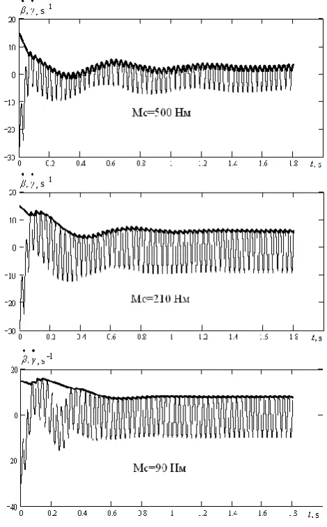
Similarly, we can get the periodical solutions for other modes (Figure 6).
Fig. 6. Graphs of the angular velocities of the driven and the output shafts depending on time in the area of high values of the drag torque
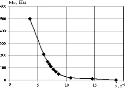
[image:4.595.52.283.489.640.2]ideal characteristic, which once again underlines the prospects of using of the inertial transmission in machinery for various purposes.
Fig. 7. Graph of the external characteristic of the inertial transmission
V. CONCLUSION
The suggested transmission is more reliable and has high load ability in compare with the known designs of inertial continuously variable transmissions. It reduces number of overrunning clutches, which are limiting the reliability of the transmission. The elastic links which are setting into the design of the transmission instead of the body overrunning clutch does not limit the reliability of the transmission. The numerous examples of the successful use of elastic connections prove it.
In the suggested design of the inertial transmission, the peak load on the output overrunning clutch is significantly reduced due to the accumulation of potential energy in the elastic elements. The reduction of the load can be more than 3 times.
The conventional mathematical models for rigid and elastic inertial torque transformers consist of a set of significantly nonlinear systems of differential equations, which must be solved in separate sections. The results must be stitched together at the boundaries between the sections. Analysis of these systems is difficult since the boundary conditions between sections must constantly be monitored. Suggested approach proposes reduction of the mathematical models of the transmission to a single system of differential equations, in which the initial conditions need only be specified at the beginning of the solution. The mathematical model is considerably simplified.
In this paper, the physical and mathematical models of the suggested transmission are developed, and the mathematical model is reduced to only one system of nonlinear differential equations. The received solutions of the mathematical model confirmed the validity of the theoretical proposals. It is shown that the resulting external characteristic is close to an ideal one. This result indicates the potential for widespread usage of the inertial transmission in drives of different engineering systems for various applications.
REFERENCES
[1] Leonov, A.I., "Inertial Automatic Torque Transformers," Moscow: Mashinostroenie, 1978.
[2] Blagonravov, A.A., "Stelpess Mechanical Transmission of Impulse Type," Automobile Industry, #5, 2007, pp. 11-14.
[3] Veytz, V.A., "Dynamics of Machine Units," Leningrad: Mashinostroenie, 1969.
[4] Poletskii, A.T. and Vasin, G.G., "Integrating the Equations of an Inertial Torque Transformer," Machine Dynamics, Moscow: Mashinostroenie, 1969, pp. 64-69.
[5] Alyukov, S.V., "Improved Models of Inertial Torque Transformers," Russian Engineering Research, 2010, vol. 30, #6, pp. 535-542.
[6] Alyukov, S.V., "Approximation of step functions in problems of mathematical modeling," Mathematical Models and Computer Simulations, vol. 3, Issue 5, 1 October 2011, pp. 661-669. [7] Keller, A., Murog, I., and Aliukov, S., "Comparative Analysis of
Methods of Power Distribution in Mechanical Transmissions and Evaluation of their Effectiveness," SAE Technical Paper 2015-01-1097, 2015, doi:10.4271/2015-01-1097.
[8] Aliukov, S. and Gorshenin, V., "On the Question of External Characteristic of the Inertial Continuously Variable Transmission," SAE Technical Paper 2014-01-1733, 2014, doi:10.4271/2014-01-1733.
[9] Keller, A. and Aliukov, S., "Rational Criteria for Power Distribution in All-wheel-drive Trucks," SAE Technical Paper 2015-01-2786, 2015, doi:10.4271/2015-01-2786.
[10] Keller, A. and Aliukov, S., "Analysis of possible ways of power distribution in an all-wheel drive vehicle," Lecture Notes in Engineering and Computer Science, vol. 2218, 2015, pp. 1154-1158.
[11] Aliukov, S., Keller, A., and Alyukov, A., "Dynamics of Overrunning Clutches of Relay Type," SAE Technical Paper 2015-01-1130, 2015, doi:10.4271/2015-01-1130.
[12] Aliukov, S., Keller, A., and Alyukov, A., "Method of Calculating of Relay Type Free-Wheel Mechanism," SAE Technical Paper 2015-01-2782, 2015, doi:10.4271/2015-01-2782.
[13] Keller, A. and Aliukov, S., "Methodology of System Analysis of Power Distribution among Drive Wheels of an All-wheel drive Truck," SAE Technical Paper 2015-01-2788, 2015, doi:10.4271/2015-01-2788.
[14] Alyukov, S., Gladyshev, S., “Dynamics of an Inertial Continuously Variable Transmission with High Load Ability,” SAE Technical Paper 2013-01-2442, 2013, doi:10.4271/2013-01-2442.
[15] Alyukov, S.V., "Characteristic of an improved continuous inertial transmission," Russian Engineering Research, vol. 34, Issue 7, 1 July 2014, pp, 436-439.