I.
I I.
III.
IV ..
PRIAM SMART IN'fERE'ACE PRODUCT SPECIFICA1'ION
INTRODuc'rION A. B.
c.
Purpose General Features n,:.~C"r;nj-i(')n- - - r - - - ..
PRODUCT DESCRIPTION A.
B. C. D. E.
Physical Characteristics Power Requirements
Environmental Characteristics Reliability
Controls
ELECTRICAL INTERFACE A.
B.
Interface Signals
Data 'l'ransfer To/From the SMART Interface FUNCTIONAL INTERFACE
At> B.
c ..
Command Initiation Transaction Status Command Descriptions
Completion Acknowledge Read Dr i ve rrype
Read Drive Parameters
Format Disc with Defect Mapping Specify Bad Sector
Specify Bad Track Format Disc
Format Cylinder Format Track
Build Defect Directory
D"""''"''''!orl n ... +:=""" ... n": ~"'_.a-__ ."
""'1;;<01.,", ,v'l;;;.L.CV I.. V.A.J. 'l;;;'" I..VJ.:t
Write Data Read Data
Read Internal Status Read Drive Status Software Reset
Sequence Up - Return Sequence Up - wait Sequence Down
D.
Read ID
Read ID Immediate Read Skip Defect Field Write Skip Defect Field
Write Disc - Full Track Write Cylinder - Full Track write Full Track
Verify Disc Verify Cylinder Verify Track Verify Data Verify ID Seek
Drive Restore Write Buffer Read Buffer Error Retry Technique APPENDIX A - Disc Format
APPENDIX B - Defect Mapping
38 39 39 40 40 41 41 42 42 43 43 44 45 46 46
47 47
A-I
Figure 1
Figure 2
1i'.;I"""f" .... O
.L:.I.~yb~ 3
Figure Al
Table 1 Table 2 'rable 3 Table 4
Table 5 Table 6 Table 7 Table 8
Table 9
'l'able 10
Table Al
Table A2 Table A3
Table A4 :,rable A5
Table Bl 'I'able 82 Table B3
FIGURES/TABLES
Register Read AC Characteristics Register Write AC Characteristics Data Request AC Characteristics Soft Sector Format
Recommended Drivers/Receivers Interface Connector Pin Assignment Control Register Assignment
SMART Interface Status Register
Transaction Status Register Completion Coce Summary Drive Fault Conditions Drive 10 Assignments
Drive Status Bit Definition Error Recovery Strategy Defect Record Format
Sector Format Summary - 3350-01 Sector Foru~t Summary
Sector Format Summary - 3450/2050 Sector Format Sumrnary '1\"71\
- ~v I V
Defect Directory Format
Defect Directory Entry Format
Alternace Areas (Cylinders) by Drive Type
I. INTRODUCTION A. Purpose
This specification describes the performance, the logical interface, the electrical interconnection, and the physical interconnection of the PRIAM SMART Interface. This document provides the reference ,
to connect
Interface to a host system with or without the use of a Direct Memory Access (DMA) port.
B. General Description
The PRIAM SMART Interface is a complete preprogrammed microprocessor-based controller for the entire line of PRIAM Winchester disc
drives. Up to four drives in any combination may be interconnected. The controller supports a variety of Read Sector, write Sector, and Format commands. The data for the sector operations is transferred across an 8-bit parallel bidirectional data bus. The data transfers may be either programmed I/O or DMA transfers. Thus, the SMART
Interface performs the entire function of detailed disc control while presenting to the host a basic and cost effective interface. The SMART Interface board may be mounted separately or attached to a PRIAM disc drive, either 8-inch or 14-inch.
C. Features
1. Controls up to four PRIAM disc drives.
2. Supports all PRIAM 8=inch and 14-inch disc products in any
combination~
3. Designed for easy attachment to the typical microprocessor bus. 4. Does all bit serialization and format related functions. The
host uses a simple byte-wide interface.
5. User-selectable sector sizes of 128, 256, 512, or 1024 bytes.
9. Automatic alternate sector assignment and read or write sector logic handle media defects transparent to the host.
10. Overlapped commands are supported. For example, three drives may be seeking, while seeking, reading, or writing on the fourth drive.
11. The SMART Interface supports implied operations. For example, issuing a Read Command to a drive in which the disc is not turning will cause the drive to Sequence Up, Restore, SeeK to the desired cylinder, Select the appropriate head, and Read the desired sector.
12. Versatile verify functions may be used for seek verification, sector data verification, track data verification, cylinder data verification, and complete disc data verifications.
II. PRODUCT DESCRIPTION*
A. Physical Characteristics
The SMART Interface logic is packaged on a single printed circuit board (13.75 by 8.30 inches) which may be mounted on either a 14-inch or 8-inch drive. There are three connectors: one for the host bus connector, one for drive connection, and a third for DC power. B. Power Requirements
+ 5 VDC,
±
5%, 3 AMP maximum C. Environmental Characteristics1. TEMPERATURE
a. ,Equipn~nt Operational: 150 C to 400 C (570 F to
1040 F).
b. Equipment Non-operational: -40 0 C to 600 C (-400 F to 1400 F).
c. 150 feet per minute air velocity must be maintained over base casting of attached drive.
2. HUMIDITY
a. Equipment Operational: 20% to 80% relative humidity, with a wet bulb temperature limit of 260 C (780 F) without condensation.
b. Equipment Non-operational: 20% to 80% without condensation. 3. ALTITUDE
a. 'Equipment Operational: From 1000 feet below sea level to 7000 feet above sea level.
D. Reliabili ty
1. L~TBF
The SMART Interface has an expected mean time between failures (MTBF) of 8000 power-on hours.
2. M'rTR
The SMART Interface is a field replaceable unit with a mean time to repair (MTTR) of less than 1/4 hour.
E. Controls
1. WI-A Position
If jumper Wl is in the A position PROM 12K is selected as a 2732 (this jumper is selected by a PCB trace).
2. Wl-B position
If jumper Wl is in the B position PROM 12K is selected as a 2716. 3. W2, W3, W4
If these jumpers are out, the PRIAM open loop clock or A level interface is selected.
If ~hese jumpers are in, the PRIAM closed loop clock or B level
interface is selected.
4. W5
III. ELECTRICAL INTERFACE h . Interface Signals
The interface signals are defined in this section. Table 2 shows the connector pin assignment. All SMART Interface signal connections are via a single 40 pin ribbon cable connector. See Table 1 for the
recommended drivers and receivers.
1. HCBUSO thru HCBUS7
This is the host bus. It is a high-active 8-bit wide
bidirectional bus used to transfer control, status information and data. Data is transferred across this bus by successive operations with the Disc Data Register. The most significant bit is HCBUS7. The bus is TRISTATE bidirectional with the drivers enabled when the HRD signal is active. The receivers are enabled when the HRD signal is inactive.
Recommended termination for this bus is a 330 ohm resistor to +5 volts and a 390 ohm resistor to ground. Note: High current drivers (as listed in Table 1) are required to drive the HCBUS lines.
2. HRD/
This low-active signal gates the contents of the selected
register (decode of HAD2, HADl, HADO) onto the HCBUS. See Table 3 for register decode assignment. This signal is terminated at the SMART Interface with a 220 ohm resistor to +5 volts and a 330 o~~ resistor to ground.
3. HWR/
5. RESET/
This low-active signal resets the SMART Interface logic and places it into the initialized state. The SMART Interface Busy bit will be set while initialization is in process.
This signal is terminated at the SMART Interface with a 220 ohm resistor to +5 volts and a 330 ohm resistor to ground.
6. HIR/
This low-active signal may be used by the host as an interrupt request. It is set active coincident with the setting of Command Completion bit in the SMART Interface Status Register and it is cleared upon the receipt of the Completion Acknowledge Command.
Note: Interrupts are disabled by a power-up or controller reset. Interrupts are enabled by the first Command Acknowledge.
Recommended termination for this signal is a 220 ohm resistor to +5 volts and a 330 ohm resistor to ground.
7. HREAD/HWRITE
This signal from the SMART Interface indicates the direction of data transfer across the HCBUS. If this signal is high, a read (data from SMART Interface to host) is the expected direction. When low, this line indicates that a write (data from the host to the SMART Interface) is expected.
kecommended termination for this signal is a 220 ohm resistor to +5 volts and a 330 ohm resistor to ground.
8. DBUSENA/
When low, this signal from the SMART Interface to the host indicates that the SMART Interface is enabled and ready to transfer data.
Recommended termination for this signal is a 220 ohm resistor to +5 volts and a 330 ohm resistor to ground.
9. DTREQ/
This line is active when data is required and remains active until the proper number of bytes are transferred.
Recommended termination for this signal is a 220 ohm resistor to +5 volts and 330 ohm resistor to ground.
TABLE 1 - Recommended Drivers/Receivers Signal
HCBUS7-HCBUSO
All other receivers All Other drivers
Driver/Receiver
Intel 8286,8287, National 8304B or equivalent
74LS14 or equivalent 75461,75462,75463 or equivalent
TABLE 2 - Interface Connector Pin Assignment (J2) PIN Number Signal PIN Number Signal
1 Ground 31 Reserved
2 HCBUSO 32 Reserved
3 HCBUSI 33 Reserved
4 HCBUS2 34 Reserved
5 HCBUS3 35 Reserved
6 HCBUS4 36 Reserved
7 HCBUS5 37 Reserved
8 HCBUS6 38 Reserved
9 HCBUS7 39 Reserved
10 Ground 40 Reserved
11 HRD/
12 Ground
13 HWR/
14 Ground
15 HAD2
16 HADI
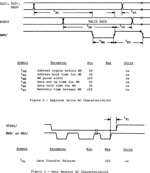
[image:11.621.124.486.312.742.2]B. Data Transfer to or from the SMART Interface
All data is transferred to or from the SMART Interface on the HCBUS lines under the control of the host-generated HWR and HRD strobe lines. l-'igures 1 and 2 show the register Read and Write AC characteristics.
Commands and parameters are usually transferred to the SMART
Interface through the use of programmed I/O. Under programmed I/O the host processor is in direct control of the I/O operation. Many of the commands also contain a data transfer phase which may transfer large blocks of data. Some host interface designers may elect to implement Direct Memory Access (DMA) for the data transfer phase of the commands.
Figures 1, 2, and 3 are valid for command or data transfers using programmed I/O or DMA data transfers.
HAD 2 , HADl,
--r
~ ---It;~L.---tAR
HRD/
---\-t
RR=i,:. .
~
s,\
r
tlID
~ ~
tDFI-
V-t--'
HCBUS
---~X ~~D
X
_______ _
HCBUS
Symbol Parameter Min Max Units
tAR Address stable before RD 60 ns
tRA Address hold time for RD 30 ns
tRR RD pulse width 250 ns
tRO Data delay from RO 120 ns
tOF RD to data floating 40 ns
tRV Recovery time between RD 250 ns
[image:12.615.45.542.310.645.2]'YT & ... ., I II
Si---liAD2, n&ll)l,
~
~
HADD
fS---tAW
.,
---,
tWAReBUS
~
VALID DATAx==
~ f
t-
l>W{
WD--t
HWR/
\
}-~~
•
~v
Symbol Parameter Min Max Units
tAW Address stable before WR 60 ns
tWA Address hold time for WR 30 ns
tww WR pulse width 250 ns
tDW Data set up time for WR 60 ns
two Data hold time for w""R 30 ns
[image:13.615.63.547.71.629.2]tRV Recovery time between -WR 250 ns
Figure 2 - Register Write AC Characteristics
DTREQ/
HWR/
or HRD/IV. FUNC'rIONAL INTERFACE
A~ Command Initiation
Commands and data are transferred across an 8-bit bidirectional bus under control of host-generated HRD and HWR strobes. Registers within the controller are selected by decoding of three address lines: HAD2, HADI, and RADO. Information is transferred over the
TP~STATE bidirectional bus (HCBUS7 to HCBUSO). An active HRD signal
places the bus in the transmit mode; an active HWR signal places the bus in the receive mode.
Table 3 shows the addressing required to select each of the control registers.
A command is issued whenever the host loads the command register. Therefore, all the appropriate parameter registers must be loaded prior to loading the Command Register. When the Command Register is loaded, the Busy bit in the SMART Interface Status Register will be set and will remain set until the command is validated and the
parameter registers are copied into the SMART Interface local memory. A Command Reject will be set if any of the following errors occur: 1. The command is invalid.
2. The drive number is invalid.
3. The selected drive already has a command pending.
4. The command was written to the command register while busy was set.
The Host Interrupt Request (HIR) is not activated if the command is rejected during the initial command validation phase.
After the command has been accepted, a command completion is
indicated through the Controller Completion Request bit in the SMART Interface Status Register (see Table 4).
TABLE 3 - Control Register Assignment
HAD 2 HADl HAD 0 HID HWR Register
0 0 0 1 0 SMART Interface Status
0 0 1 1 0 Read Disc Data
0 1 0 1 0 Result 0 (Transaction Status)
0 1 1 1 0 Result 1
1 0 0 1 0 Result 2
1 0 1 1 0 Result 3
1 1 0 1 0 Result 4
1 1 1 1 0 Result 5
0 0 0 0 1 Command
0 0 1 0 1 Write Disc Data
0 1 0 0 1 Parameter 0
0 1 1 0 1 Parameter 1
1 0 0 0 1 Parameter 2
1 0 1 0 1 Parameter 3
1 1 0 0 1 Parameter 4
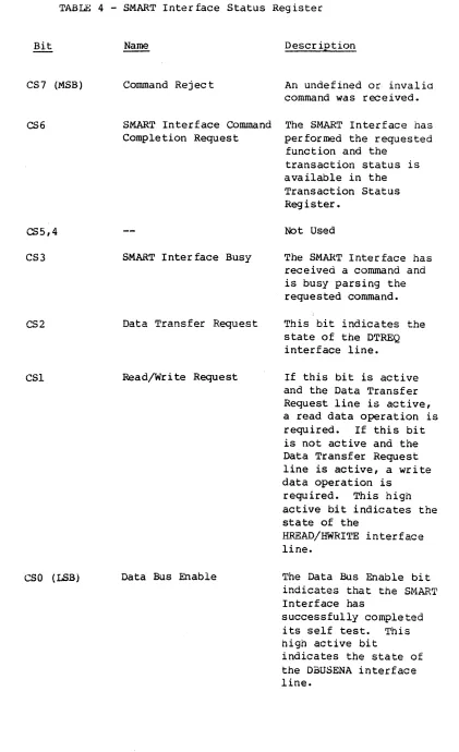
[image:15.613.71.520.82.727.2]TABLE 4 - SMART Interface Status Register
Bit
CS7 (MSB)
CS6
CS5,4
CS3
CS2
CSl
eso
(LSB)Name
Command Rej ec t
Oeser iption
An undefined or invalid command was received. SMART Interface Command The SMART Interface has Completion Request
SMART Interface Busy
Data Transfer Request
Read/Write Request
Data Bus Enable
performed the requested function and the
transaction status is available in the Transaction Status Register.
Not Used
The SMART Interface has received a command and is busy parsing the requested command. This bit indicates the state of the DTREQ interface line.
If this bit is active and the Data Transfer Request line is active, a read data operation is required. If this bit is not active and the Data Transfer Request line is active, a write data operation is
required. This high active bit indicates the state of the
B~E~~/HWRITE interface
line.
The Data Bus Enable bit Interface has
successfully completed its self test. This high active bit
[image:16.612.116.537.44.734.2]B. Transaction Status (Result Register 0)
The Transaction Status Register (Result 0) indicates the result of a SMART Interface command. The format of the Transaction Status
Register is shown in Table 5. When the SMART Interface Status Register indicates that a completion request is pending, the host processor should read the Transaction Status Register to determine the outcome of the command. The four major completion types are listed below:
1. Good Completion - 0
This type of completion indicates that the command was
successfully completed, but some steps may have been retried. The following codes are generated if the automatic retry logic is unable to recover from the error.
2. System Error - 1
These errors result from a system, controller or drive problem. 3. Operator Intervention - 2
These types of errors require human intervention for recovery. 4. Command/Drive Error - 3
Command errors are usually due to a user program error.
Bit Number: Bit Designation:
Bit Dl, DO
Tl, TO
CC3, CC2, CCl, CCO
TABLE 5 - Transaction Status Register
7 6 5 4
Dl DO Tl TO
Name Drive
Completion Type
Completion Code
3 2 1 0
CC3 CC2 eCl ceo
Description
This field indicates to which drive the transaction status applies.
This field defines the four major classes of completion. See Table
6.
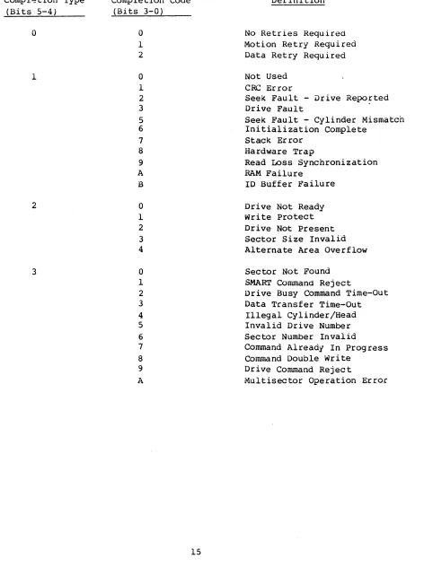
[image:18.612.79.553.85.720.2]Compl~tion Type (Bits 5-4)
o
1
2
3
TABLE 6 - Completion Code Summary
Completion Code (Bits 3-0)
0 1 2 0 1 2 3 5 6 7 8 9 A B 0 1 2 3 4 0 1 2 3 4 5 6 7 8 9 A Definltion
No Retries Required Motion Retry Required Data Retry Required Not Used
CRe Error
Seek Fault - Drive Repo~ted
Drive Fault
Seek Fault - Cylinder Mismatch Initialization Complete
Stack Error Hardware Trap
Read Loss Synchronization RAM Failure
ID Buffer Failure Drive Not Ready Wri te Protect Drive Not Present Sector Size Invalid Alternate Area Overflow Sector Not Found
SMART Command Reject
Drive Busy Command Time-Out Data Transfer Time-Out
Illegal Cylinder/Head Invalid Drive Number Sector Number Invalid
Command Already In Progress Command Double write
Drive Command Reject
[image:19.612.63.535.90.732.2]'rne following sec tion prov ides a summary of the completion codes and a detailed description of each code.
Transaction Status
(Bits 5-0) Definition
00 No Re try Required
01
02
11
12
13
15
16
This status code indicates that the command completed successfully without any retries. Motion Retry Required
This status code indicates that an automatic retry was used to recover from an error and then the command completed successfully.
Data Retry Required
This status code indicates that a data error occurred (CRC) but an automatic retry recovered from the error and completed the command
successfully. CRe Error
This status code indicates that a CRC error was detected on a read operation.
Seek Fault - Drive Reported
This status code indicates that a seek was attempted and the seek failed. The seek error was indicated in the disc drive status.
Drive Fault
This status code indicates that the operation was terminated due to one of the conditions in Table 7.
Seek Fault - Cjlinder Mismatch
This status code indicates that a seek was performed and completed by the drive, but a comparison of the drive current cylinder registers with the intended address indicated that the wrong cylinder was selected.
Ini tialization Complete
Transaction Status (Bits 5-0)
17
18
19
lA
IB
Definition Hesult 1 AA Hesult 2 55 Result 3 FO Result 4 OF Result 5 = 00
This completion does not generate an interrupt request, but it must be acknowledged by a completion acknowledge command.
Stack Error
This status code indicates that a hardware
failure occurred that resulted in an instruction fetch from a nonexistant program memory location. Hardware Trap
This status code indicates that an unexpected processor interrupt (trap) occurred.
Read Loss Synchronization
RAM
1D
This status code indicates that read operation was terminated before the expected number of data bytes were read from the disc.
Failure
This status code indicates that the micro-diagnostics have detected a bad RAM location.
The result registers have the following meanings: Result 1
=
Expected DataResult 2
=
Received Data Result 3=
Memory Address MSB Result 4=
Memory Address LSB Buffer FailureThis status code indicates that the micro-diagnostics have detected an error in the 1D buffer.
Transaction Status
, R; +-c> c;. _ ( l \ n", J;: ~ ~ ~ ... ~ ~ ~
\~ ... ~v - i Vi .i .... H~::.L..i..i.i..i..~..i..Uii
20 0rive Not Ready
21
22
23
24
30
31
32
33
34
This status code indicates that the S~~Rr
Interface attempted to sequence up the drive and the drive did not indicate that it was ready
within the expected period of time.
write Protect
This status code indicates that a write operacion was attempted on a write-protected drive.
Drive Not Present
The drive sgecified is not connected or not powered up.
Sector Size Invalid
The sector switches on the drive are set incorrectly.
Alternate Area Overflow
This status code indicates that there are more defective sectors or tracks than there are spare sectors or tracks on the disc.
Sector Not Found
This code indicates that the specified logical sector could not be located.
SMART Command Reject
The received command is not supported by the SMART Interface.
Drive Busy Command Time-out
This status code indicates that the SMART
Interface issued a command to the drive and the drive did not properly complete the command. Data Transfer Timeout
This status code indicates that the SMART Interface requested a data transfer and the transfer was not completed within 3 seconds. Illegal Cylinder/Head
Transaction Status
(Bits 5-0) Definition
35 Invalid Orive Number
This code indicates that a drive number gredter than three was specified as a parameter.
36 Sector Number Invalid
This code indicates that a physical operation, as distinguished from a logical operation, failed to find the specified sector.
37 Command Already In Progress
38
39
3A
This code indicates that the specified drive already had a command in progress.
Command Double write
This error occurs if the host writes to the command register when the SMART Interface Busy bit is set.
Drive Command Reject
This error code indicates either a SMART Interface or drive hardware failure. Multisector Operations Error
This error code indicates that a read or write data command was issued with a multisector count equal to zero or greater than 7F HEX.
TABLE 7 - Drive Fault Conditions
C. Command Descriptions
This section defines each of the SMART Interface cOimnands.
Each command descr iption spec ifies the parameters required and the results obtained.
There is a corrnnon format used for h,,+- h parameter ~..,.~ .... ,...~I"t 1 ... registers
t.J'IoJ'\.o" ... QUI..l .LO;::;VU..L",
used in most commands.
The formats of the most common parameter registers are as follows: Parameter Register 0
Bit Number 7 6 5 4 3 2 1 0
Bit Designation 0 0 0 0 0 0 Dl DO
where: 0
1 DO
0 0 Drive 1
0 1 Drive 2
1 0 Drive 3
1 1 Drive 4
Parameter Register 1
Bit Number 7 6 5 4 3 2 1 0
Bit Designation 0 H2 Hl HO Cli CIO C9 C8
where: H2, HI, HO define the target head address and CIl, CIO, C9, C8 are the upper binary bits of the target cylinder address.
n~""..~",,,,,,,,,,,,,,,W'" n",..;,..4-""" .... 2
~Q.LQU,O;::; ... O;::;.L ,"-1;,=,.l.Q,-'I;;.L
Bit Number 7 6 5 4 3 2 I 0
-0': .,..
Designation ".., " c "C- " A C3 C2 Cl CO
... .1. ' - \.,1 \"0 \"J \.,'t
Parameter Register 3
Bit Number 7 6 5 4 3 2 1 a
Bit Designation a S6 S5 54 S3 S2 51 SO
where: S6 through SO are the 7 binary bits defining the target sector.
Parameter Register 4
Bit Number 7 6 5 4 3 2 1 a
Bit Designation 0 M6 M5 M4 M3 M2 Ml MO where: M6 through MO are the 7 binary bits defining the total
number of consecutive logical sectors to be written.
The formats of the most common result registers are as follows: Result Register 0
See Table 5 for the Result Register 0 definition. Result Resister 1
Bit Number 7 6 5 4 3 2 1
o
Bit Designation
o
H2 HI HO CII CIO C9 C8where: H2, HI, HO define the current selected head address and ClI, CIa, C9, are the upper binary bits of the current cylinder address
Result Register 2
Bit Number 7 6 5 4 3 2 1
o
Result Register 3
Bit Nwnber 7 6 5 4 3 2 1 0
Bit Designation 0 86 85 84 83 52 81 SO where: 86 through SO define the number of the last sector.
Result Register 4
Bit Number 7 6 5 4 3 2 1 0
Bit Designation 0 1'-16 M5 M4 M3 M2 Ml MO
where: 1~6 through MO indicate the residual sector count (non-zero
Command Definitions
Using the parameter and result register formats provided, the following
~ommand definitions apply to the SMART Interface.
Command: Completion Acknowledge Command Code: 00 HEX
Parameters: None Results: None Data Transfer: None
Function: Upon completion of a previously issued,command the Command Completion Request bit in the SMART Interface Status Register will be set. When this bit is set, the host system should read the appropriate result registers, and reset the Command Completion Request bit by issuing the Completion Acknowledge command.
Command: Command Code:
If a command for another drive has been completed, i.e., overlapped seeks, the bit will be set immediately after updating the result registers, requ1r1ng another Completion Acknowledge command to clear it.
Read Drive Type 86 HEX
Parameters: Parameter 0 - Drive Address Results: Result 0 - Transaction Status
TABLE 8 - Drive ID Assignment
ID Code (HEX) Drive Designation
1"\1'\
uu Invalid
01 DISKOS 3350-01 or -10 (20,160 bytes/track) 02 DISKOS 3350-01 (19,960 bytes/track)
03 DISKOS 3450 (12,960 bytes/track) 04 DISKOS 3450 (13,440 bytes/track) 05 DISKOS 2050 (13,440 bytes/track)
06 DISKOS 6650
07 DISKOS 15450
08-0F Reserved
10 DISKOS 570-1
11 DISKOS 1070-1
12 CD8005
13 CD80l0
14 DISKOS 570-2
15 DISKOS 1070-2
16-1F Reserved
[image:28.613.115.507.64.733.2]Command: Read Drive Parameters Command Code: 85 HEX
Parameters: Parameter 0 - Drive Address Results: Result 0 - Transaction Status
Result 1 - Number of Heads/Number of Cylinders MSB Result 2 - Number of Cylinders LSB
Result 3 - Number of Sectors Per Track Result 4 - Logical Sector Size MSB Result 5 - Logical Sector Size LSB Data Transfer: None
Function: This command may be used by a software driver that is set up to handle multiple disc types. Through the use of this command, the driver can determine the parameters required to use the disc.
Command: Comma nd Code:
The Read Drive Parameters command returns the number of user data cylinders available. If defect mapping is enabled, the cylinders reserved for alternate sectors or tracks are not included in the number of cylinders reported.
Format Disc With Defect Mapping
A8 HEX
Parameters: Parameter 0 - Drive Address Results: Resul,t 0 - Transaction Status Data Transfer: None
Command: Specify Bad Sector Command Code: AA HEX
Pa rarneter s: Parameter 0 ~ Drive Address
Parameter 1
-
Head/Cylinder MSBParameter 2
-
Cylinder LSB Parameter 3-
Physical Sector Results: Result 0 - Transaction Status Data Transfer: NoneFunction: This command is used by a host routine to request that the SMART Interface flag a bad sector and assign an alternate.
Command: Command Code:
This command should only be used when the host logic identifies
a
bad sector that is not specified in the Skip Defect Field.Before this command may be executed, the disc must be formatted with defect mapping enabled.
Specify Bad Track A9 HEX
Parameters: Parameter 0 - Drive Address Parameter 1 - Head/Cylinder MSB Parameter 3 - Cylinder LSB Results: Result 0 - Transaction Status Data Transfer: None
Function: This command is used by a host routine to request that the SMART Interface flag a bad track and assign an alternate. This command should only be used when the host logic identifies a bad track that is not specified in the Skip Defect Field.
Command: Format Disc
Command Cod e: AO HEX
Parameters: Parameter 0 - Drive Address Results: Result 0 - Transaction Status Data Transfer: None
Function: This command is used to format the disc without defect
mapping. This command or the Format Disc with Defect Mapping should be used whenever a new sector size is selected through the sector switches on the disc drive.
The disc format is described in Appendix A.
Command: Format Cylinder
Conunand Code: Al HEX
Parameters: Parameter 0 - Drive Address Parameter 1 - Cylinder MSB Parameter 2 - Cylinder LSB Results: Result 0 - Transaction Status Data Transfer: None
Function: This command is used to format a single cylinder on the disc or discs (see Format Disc command).
Command: Format Track
Command Code: A2 HEX
Command: Build Defect Directory Command Code: A7 HEX
Parameters: Parameter 0 - Drive Address Results: Result 0 - Transaction Status Data Transfer: None
Function: This command performs the Defect Directory initialization portion of the Format Disc with Defect Mapping command. Appendix B describes the defect map format.
Command: Command Code: Parameters:
This command is not required if the Format Disc with Defect Mapping command is issued.
Read Defect Directory
A6 HEX
Parameter 0 - Drive Address
Parameter 3 - Directory Entry (0 or 1) Results: Result 0 - Transaction Status
Data Transfer: 128 bytes of data are transferred from the SMART Interface ~o
the host.
Command: Command Code:
Parameters:
Results:
write Data
52 HEX - Retry Enabled 42 HEX - Retry Disabled Parameter 0 - Drive Address Parameter 1 - Head/Cylinder Parameter 2 - Cylinder LSB Parameter 3 - Sector
MSB
Parameter 4 - Multisector Count Result 0 - Transaction Status Result 1 - Head/Cylinder MSB Result 2 - Cylinder LSB Result 3 - Sector
Result 4 - Multisector Count
Data Transfer: This command will cause data to be transferred from the host to the SMART Interface.
Function:
If the user requested data will fit in the 1024-byte buffer, all the data is transferred in one block.
If the total data to be written is greater than 1024 bytes, the data transfer is broken into multiple 1024-byte block data transfers from the host with the data being written to the disc between block transfers.
If a Write Data Command requires a head switch or a seek
because the multisector operation crossed a track boundry, the data transfer request is broken at the head switch or seek operation even if more data could have been placed in the buffer.
c.
If the read/write head is not over the desired cylinder, a seek is issued to the drive to position the head at the target cylinder.D. Data is transferred from the host (see Data Transfer described above) to the SMART Interface.
E. The correct head is selected and consecutive ID fields on the target track are read until a match is found between the recorded logical sector number and the
parameter-specified sector number.
F. The data field is written from the buffer.
G. The multiple sector count from Parameter Register 4 is decremented.
H. If the multiple sector count has terminated, then command is complete and the appropriate Result Registers are updated.
I. If the multiple sector count is non-zero, the sector number is incremented (modulo the number of sectors per track); then the buffer contents are checked= If the buffer is empty, then Step D is executed. Since the buffer is 1024 bytes, and sectors may be 128, 256, or 512 bytes; the ensuing sector data may be resident in the buffer. If the sector number is zero, then the next head is selected
unless currently on the last head of the cylinder. If not, Step E is executed. If the last head is selected, the head address is set to zero and the cylinder address is
incremented. Step C is then performed.
Command: Command Code:
Parameter s:
Results:
Read Data
53 HEX - Re try Enabled 43 HEX - Retry Disabled Parameter 0 - Drive Address Parameter 1 - Head/Cylinder Parameter 2 - Cylinder LSB Parameter 3 - Sector
MSB
Parameter 4 - Multisector Count -Result 0 - Transaction Status
Result 1 - Heads/Cylinders MSB Result 2 - Cylinders LSB
Result 3 - Sector
Result 4 - Multisector Count
Data Transfer: This command will cause data to be transferred from the SMART Interface to the host.
Function:
If the user requested data will fit in the 1024 byte buffer, all the data is read into the buffer before a data transfer request is made to the host.
If the total data to be read is greater than 1024 bytes, the data transfers are broken into multiple 1024 byte blocks read
from the disc and then transferred to the host.
If a Read Data Command requires a head switch or a seek
because the multisector operation crossed a track boundry, the data transfer request is broken at the head switch or seek operation even if more data could have been placed in the buffer.
The Read Data command causes data to be read from the disc in accordance with the parameters specified.
The command execution sequence is described below:
A. A Fault Reset is issued to the drive if the Drive Fault status bit is active.
B. If the drive is not ready the controller will issue a
E. Consecutive ID fields on the target track are read until a match is found between the recorded logical sector number
and the parameter specified sector number.
F. Then the data field is read from the disc into the buffer. G. The multiple sector count in Parameter Register 4 is
decremented.
H. If the multiple sector count is zero, then a data transfer request from the controller to the host is signalled. The controller waits for the data transfer to complete and when complete, the Command Completion bit is set and the Result Registers are updated.
If the multiple sector count is non-zero, then the sector count is updated; also head and cylinder address are
updated as required. If buffer space is available for the next sector, step E is repeated and the sequence is
continued.
Command: Read Internal Status Command C0de: 05
Parameters: None
Results: Result 0 - Transaction Status
Result 1 - Internal Status (Described below) Data Transfer: None
Function: If the command reject bit in Controller Status Register is set, the Read Internal Status Command may be used to determine why the command was rejected. The Internal Status Code
returned in Result Register 1 will be one of the transaction status codes listed in Table 6.
Command: Read Drive Status Command Code: 06 HEX
Parameters: Parameter 0 - Drive Address Results: Result 0 - Transaction Status
Result 1 - Drive Status (see Table 9) Data Transfer: None
Function: The Read Drive Status command is used to obtain the status of the drive selected by parameter register
o.
Result Register 1
Bit
B7 (MSB)
B6
B5
B4
B3
82
B1
80 (LSB)
TABLE 9 - Drive Status Bit Definition
Name
Command Reject
Write Protect
Drive Fault
Busy
Cylinder Zero Seek Fault Seek Complete Ready
Oeser iption
Control or Register Load command received while drive is not ready, or improper command received.
The head selected is write protected. Write protection is set by switches in the drive or when the drive is not sequenced up. A fault was detected during a write
operation or a drive unsafe condition was detected.
The drive is in process of executing a command.
The access arm is set to Cylinder O.
A fault was detected during a seek operation.
This bit is set when a seek operation is completed.
Command: Command Code: Parameters: Results: Data Transfer Function:
Command: Command Code: Parameters: Results:
Data Transfer: Function:
Software Reset 07 HEX
None
Result 0 - Transaction Status None
This command causes the SMART Interface to abort all inprogress commands and run the microdiagnostics.
Sequence Up - Return 83 HEX
Parameter 0 - Drive Address Result 0 - Transaction Status
Result 1 - Drive Status (see Table 9) None
Corr~nd: Sequence Up - Wait
Comr~nd Cod~: 82 HEX
Parameters: Parameter 0 - Drive Address
Results: Result 0 - Transaction Status
Result 1 - Drive Status (see Table 9) Data Transferred: None
Bunction: The Sequence Up - Wait command causes the disc drive defined by the contents of Parameter Register 0 to power its spindle motor. The disc drive will monitor the rotational speed of the disc and when it is at speed and stable, the drive will position the heads at cylinder zero. When this is completed the Command Completion bit will be set with the drive status in Result Register 1.
Command: Command Code: Parameters: Results:
The Sequence Up - Wait command is similar to the Sequence Up - Return command except this command will require about 30 seconds to complete.
Sequence DOwn 81 H~
Parameter
o -
Drive Address Result 0 - Transaction StatusResult 1 - Drive Status (see Table 9) Data Transferred: None
Command: Command Code:
Parameters:
Results:
write ID
55 HEX - Retry Enabled 45 HEX - Retry Disabled Parameter 0 - Drive Address Parameter 1 - Head/Cylinder MSB Parameter 2 - Cylinder LS8
Parameter 3 - Physical Sector Number
Parameter 4 - Multisector Count (1 to number of sectors/track)
Result
o -
Transaction StatusResult 1 - Head/Cylinder Address MSB Result 2 - Cylinder Address LSB Result 3 - Physical Sector Address Result 4 - Residual lvlultisector Count
Data Transferred: The 4 byte ID field data is transferred from the host to the SMART Interface.
Function:
Byte 0 - Logical Sector Number Byte 1 - Head/Cylinder MSB Byte 2 - Cylinder LSB
Byte 3 - ID Control Value = FF HEX (See Appendix B.) A 4 byte ID field will be transferred for each ID field written.
This command causes the 4 byte ID field to be written at the physical sector location specified. The logical sector number is recorded from the buffer data. The command
execution sequence is similar to the Write Data command with the following exception. The writing is enabled when the physical sector count (number of sector marks past index) matches the sector number.
Command: Command Code:
Parameters:
Results:
Read 10
56 HEX - Retry Enabled 46 HEX - Retry Disabled Parameter 0 - Drive Address Parameter 1 - Head/Cylinder MBB Parameter 2 - CYlinder LSB
Parameter 3 - Physical Sector Number
Parameter 4 - Multisector Count (1 to number of sectors/track)
Result 0 - Transaction Status
Result 1 - Head/Cylinder Address MSB Result 2 - Cylinder Address LSB Result 3 - Physical Sector Address
Result 4 - Residual Multisector Count
Data Transferred: The 4 byte ID field data is transferred from the SMART Interface to the host.
Function:
Byte 0 - Logical Sector Number Byte 1 - Head/Cylinder MSB Byte 2 - Cylinder LSB
Byte 3 - 10 Control Value (see Appendix B)
A 4 byte 10 field will be transfered for each 10 field read. This command causes the 4 byte 10 field to be read from the physical sector location specified.
The multisector count may not be greater than the number of sectors on a track.
Command: Canmand Code:
Read ID Immediate
57 HEX - Retry Enabled 47 HEX - Retry Disabled
~aramet~rs: Parameter 0 - Drive
Parameter 1 - Head/cylinder MSB Parameter 2 - Cylinder LSB Results: Result 0 - Transaction Status
Data Transferred: The 4 byte ID field data is transferred from the SMART Interface to the host.
Function:
Command: Conunand Code:
Byte 0 - Logical Sector Number Byte 1 - Head/CYlinder MSB Byte 2 - CYlinder LSB
Byte 3 - ID Control Value (see Appendix B)
This command causes the ID field at the next physical sector encountered to be read.
Read Skip Defect Field 59 HEX - Retry Enabled 49 HEX - Retry Disabled Parameters: Parameter 0 - Drive Address
Parameter 1 - Head/cylinder MSB Parameter 2 - Cylinder LSB
Parameter 4 Multisector Counter = 1 Results: Result 0 - Transaction Status
Command: CC!.TtTUand Code:
Parameters:
Write Skip Defect Field SA HEX - Retry Enabled 4A HEX - Retry Disabled Parameter 0
-
Drive Address Parameter 1-
Head/Cylinder Parameter 2-
Cylinder LSBMSB Parameter 4
-
Multisector Count = 1 Results: Result 0 - Transaction StatusData Transferred: The 8 byte Skip Defect Record is transferred from the host to the SMART Interface. See Appendix A for the Skip Defect Field forma t.
Function: This command causes the 8 byte Skip Defect Field to be written to the location specified. The record checksum is automatically computed and appended to the record.
A Write Fault will occur if this command is attempted without disabling the drivels Skip Defect Field protection feature.
Command: Write Disc - Full Track Command Code: AS HEX
Parameters: Parameter 0 - Drive Address Results: Result 0 - Transaction Status
Result 1 - Head/Cylinder MBB Result 2 - Cylinder LSB Result 3 - Sector
Data Transferred: This command will cause data to be transferred from the
Function:
host to the S~ART Interface.
128, 256, 512, or 1024 bytes of data are transferred depending upon the selected sector size.
This conuoand is used to initialize the disc data fields. The data pattern transferred is written to all data fields on the disc.
Command: Write Cylinder - Full Track Command Code: AC HEX
Parameters: Parameter 0 - Drive Address Parameter 1 - Cylinder Msa Parameter 2 - Cylinder LSB Results: Result 0 - Transaction Status
Result 1 - Head/Cylinder MSB Result 2 - Cylinder LSB Result 3 - Sector
Data Transferred: This command will cause data to be transferred from the host to the SMART Interface.
Function:
Command: Command Code: Parameters:
Results:
128, 256, 512, or 1024 bytes of data are transferred depending upon the selected sector size.
This command is used to initialize the disc data fields on a cylinder of the disc~ The data pattern transferred is written to all data fields on the cylinder selected by Parameters 1 and 2.
Write Full Track AD HEX
Parameter 0 - Drive Address
Parameter 1 - Head/Cylinder MSB Parameter 2 - Cylinder LSB
Result 0 - Transaction Status
Command: verify Disc A3 HEX
Parameters: Parameter 0 - Drive Address Results: Result 0 - Transaction Status
Result 1 - Head/Cylinder MSB Result 2 - Cylinder LSB Result 3 - Sector
Data Transferred: None
Function: This command is used to verify that a disc is formatted properly. Every IO and Sector on the disc is read and the CRe is performed. If an error is detected, the operation
is terminated and the result registers indicate which sector is in error.
Command: Verify Cylinder Command Code: A4 HEX
Parameters: Parameter 0 - Drive Address Parameter 1 - Cylinder MBB Parameter 2 - Cylinder LSB Results: Result 0 - Transaction Status
Result 1 - Head/Cylinder MSB Result 2 - Cylinder LSB Result 3 - Sector
Data Transferred: None
Command: Command Code: Parameters:
Results:
Data Transferred: Function:
Command: Command Code: Parame ter s:
Results:
Data Transferred: Func tion:
Verify Track A5 HEX
Parameter 0 - Drive Address Parameter 1 - Head/Cylinder MSB Parameter 2 - Cylinder LSB Result
o -
Transaction Status Result 1 - Head/Cylinder MSB Result 2 - Cylinder LSB Result 3 - SectorNone
This command is used to verify that a single track of the disc is formatted properly. Every ID and sector on the specified track is read and the CRC is performed. If an error is detected, the operation is terminated and the result registers indicate which sector contains the error.
Ver ify Data 44 HEX
Parameter 0 - Drive Address
Parameter 1 - Head/Cylinder MSB Parameter 2 - Cylinder LSB Parameter 3 - Sector
Parameter 4 - Mlltisector Count
Result 0 - Transaction Status Result 1 - Head/Cylinder MSB Result 2 - Cylinder LSB Result. 3 - Sector
Result 4 - Residual Multisector Count None
Command: Verify ID
Cormnana Code: 48 HEX
Parameters: Parameter a - Drive Address Parameter 1 - Head/Cylinder MSB Parameter 2 - Cylinder LSB Parameter 3 - Sector
Parameter 4 - Multisector Count Results: Result a - Transaction Status
Result 1 - Head/Cylinder MSB Result 2 - Cylinder LSB Result 3 - Sector
Result 4 - Residual Multisector Count Data Transferred: None
Function: This command is used to verify that the ID fields on a track are readable. Every ID field specified by the
parameter registers is read and the CRC is checked. If an error is detected, the operation is terminated and the
Command: Command Code:
Seek
51 HEX - Retry Enabled 41 HEX - Retry Disabled Parameters: Parameter 0 - Drive Address
Parameter 1 - Head/Cylinder MSB Parameter 2 - Cylinder LSB Results: Result 0 - Transaction Status
Result 1 - Current Cylinder MSB Result 2 - Current Cylinder LSB Data Transferred: None
Function: The Seek Command uses the drive address defined in Parameter Register 0 and the contents of Parameter
Registers land 2 for the target cylinder address and head address.
The SMART Interface will command the drive to seek to the target cylinder and select the specified head. When this is complete, the Command Completion bit will be set with the current cylinder MSB in Result Register 1 and current cylinder LSB in Result Register 2 as discussed in the Restore Command section.
If the Retry bit is set, the seek will be retried if the first attempt is unsuccessful. This retry will be reported in the Transaction Status Register.
Also, Sequence Up is implied upon the receipt of this command if the selected drive is sequenced down when this command is received by the SMART Interface.
The seek command is automatically issued by the S~~RT
Command: Drive Restore Command Code: 40 HEX
Parameters: Parameter 0 - Drive Address Results: Result 0 - Transaction Status
Result 1 - Current Cylinder MBB Result 2 - Current Cylinder LSB Data Transferred: None
Function: The Restore Command causes the access arm on the drive defined by the contents of Parameter Register 0 to be
Command: Command Code:
positioned over Cylinder
o.
Upon completion of the disc's restore operation, the
Command Completion bit is set with the current cylinder MSB in Result Register 1 and current cylinder LSB in Result Register 2.
If the application program is using the SMART Interface with retries enabled, the Restore command is automatically issued when required.
Write Buffer 04 HEX Parameters: None
Results: Result 0 - Transaction Status
Data Transferred: 1024 bytes of data are transferred from the host to the SMART Interface.
Function~ This command may be used in conjunction with the Read
Buffer command to test the SMART Interface data buffer. Data may be transferred either via DMA or by successive writes of the Disc Data Register. The command completion bit is set when the last byte required to fill the buffer is transferred.
The write buffer command is used to transfer data from the host to the SMART Interface data buffer.
Command: Read Buffer Command Code: 03 HEX
Parameters: None
Results: Result 0 - Transaction Status
Data Transferred: 1024 bytes of data are transferred from the SMART Interface to the Host.
Function: The Read Buffer command may be used to list the buffer contents, to verify the buffer or in error recovery operations. Data may be transferred either via a DMA channel or by successive reads of the Disc Data Register. The Command Completion bit is set when the last byte in the buffer is read.
The Read Buffer Command is not required for normal SMART Interface operation.
o.
Error Retry TechniqueIf an error occurs during the execution of the command and the retry feature is selected (i.e., retries are enabled), the SMART Interface will automatically retry the command.
The command is aborted and the appropriate transaction status is
immediately returned to the host if retries are not enabled. Table 10 outlines the retry strategies employed.
All of the commands that require accessing data are preceded by a seek to the correct cylinder before the data transfer is begun. If the command is a logical data access, the disc cylinder is verified by reading the 10
TABLE 10 - Error Recovery Strategy
Error Type
CRC Error Seek Fault Drive Fault Drive Not Ready Write Protect Sector Not Found Command Reject Command Timeout
Data Transfer Timeout Illegal Cylinder/Head
1. Retry Procedures
Retry Procedure
b c d d
None e None d a None
a. The command must be reissued by the host.
b. The SMART Interface will automatically reissue a transaction that results in a CRC error four times.
c. If a seeK fault occurs, the SMART Interface will reset the seek fault and retry the seek four times.
d. A reset is issued to the drive and the command is retried four times.
APPENDIX A - Disc Format
1. Sector Forma.t
The sector format used by the SMART Interface is shown in Figure AI. Each track starts with an INDEX pulse, which corresponds to a cert.ain position on the servo track. The servo track also provides
rotational posit.ion information for the generation of SECTOR pulses. A sector pulse precedes each record and successive records are
separated by gaps within which the sector pulses occur. a. Pre-Record Gap (Gap 1)
The Pre-Record Gap, or Gap 1, appears at the beginning of every record. It consists of 23 bytes of zeros. The length of Gap 1
never varies. The first Gap 1, after INDEX, is followed by the Skip Defect Record. All other Gap lis, after SECTOR pulses, are followed by ID records.
b. Skip Defect Record
The Skip Defect Record (Table Al) consists of 11 bytes: a Data Sync using the hexadecimal pattern FB, the physical address of the first defect using 2 bytes, the physical address of the second defect using 2 bytes, the physical address of the third defect using 2 bytes, a checksum across the previous 6 bytes using 2 bytes, and fill characters of zeros using 2 bytes.
If a physical address is 0000, then there are not any additional defects on the track.
If the physical address of the first defect is FFFF HEX, the track is defective.
Decimal Location
TABLE Al - Defect Record Format
DATA SKIP DATA DATA
FIELD GAP GAP DEFECT GAP GAP FIELD GAP GAP FIELD GAP
N
II
I
Index: Gap 1: Skip Defect Record:
Sector Mark: ID Field:
Gap 2:
Data Field:
Gap 3:
3 1
1
1
INDEX
RECORD 1 ID1 2 1 . 1 ..
1
1 1 1
l
1st SECTOR 2nd SECTOR
MARK MARK
Derived from servo track Zeros
Data Sync, FB Hex 1st defect address 2nd defect address 3rd defect address Checksum
Fill characters - zeros
ID2 2
1
I
1
Derived from INDEX and servo clock ID Sync, F9 Hex
Sector address
Head and high cylinder address Low order cylinder address ID Control
2 1 ID3
l
I
3rd SECTOR
MARK
23 Bytes
1 Byte 2 Bytes 2 Bytes 2 Bytes 2 Bytes 2 Bytes
1 Byte 1 Byte 1 Byte 1 Byte 1 Bite
1\
eRe 2 Bytes '
Fill characters - zeros 2 Bytes
Zeros 11 Bytes
1 Byte Data Sync, FD Hex
Data 128, 256, 512, or 1024 Bytes eRe
Fill characters - zeros
Zeros (size depends on data field size)
[image:54.612.50.535.66.633.2]C. 1D Field
The Identification Field contains 9 bytes: an 1D sine using the hexadecimal pattern F9, the sector number of 1 byte, the head address and high order cylinder address of 1 byte, the low order cylinder address of 1 byte, an 1D control field of 1 byte, 2 CRe
(cyclic redundancy check) bytes, and 2 bytes of zeros for filling. The cylinder and head address, along with the sector number, verify that the drive has addressed the correct track and sector. The 1D control field is discussed in Appendix B. D. 1D Gap (Gap 2)
The ID Gap, or Gap 2, separates each successive Identification Field from its Data Field. It contains 11 bytes of zeros.
E. Data Field
Following Gap 2, the Data Field consists of 135, 263, 519, or 1031 bytes depending on the selected data length. The first byte is the data sync (hexadecimal pattern FD), while the last 4 bytes consist of 2 bytes of CRC and 4 bytes of zeros for filling. Fe Pre-Index Gap (Gap 3)
The Pre-Index Gap, or Gap 3, is used only once on a track. It appears at the end of the last data field and persists until INDEX. This gap contains zeros.
The sector size is selected by setting the sector switches on the drive to the decimal physical sector size.
The following tables define the sector switch settings required to select 128, 256, 512, or 1024 byte logical sector sizes on each of the PRIAM drive types.
TABLE A3 - Sector Format Summary - 3350-10/6650/15450
Logical Size Physical Size Sectors Per Track Switch Setting
128 181 I I I 7, 6, 4, 3, 2, 1
256 309 65 7, 1
512 574 35 6, 2, 1
1024 1118 18 5, 4
TABLE A4 - Sector Format Summary - 3450/2050
Logical Size Physical Size Sectors Per Track Switch Setting
128 181 74 7, 4, 2
256 311 43 6, 4, 2, 1
512 582 23 5, 3, 2, 1
1024 1117 12 4, 3
TABLE A5 - Sector Format Summary - 1070
Logical Size Physical Size Sector Per Track Switch Setting
256 324 44 3, 2
512 648 22 4, 2
[image:56.615.56.528.96.496.2]There are two defect directory entries created. The Format Disc with Defect Mapping command proceeds as follows:
a. The entire disc is formatted including the alternate areas defined in Table B3.
b. The skip defect records are read and the bad tracks and sectors are flagged uy reformatting the sectors and tracks with the ID codes shown in Table B4.
c. The defect directory entries are created on the first available good sectors on the first cylinder of the alternate area.
d. The disc is scanned for flagged sectors or tracks and alternates are assigned.
TABLE B4 - 1D Control Field Definition ID Control Value (HEX)
FF FD FS FB FO
3. Read/Write Operations - Defect Handling
Definition User Data User Alternate Bad Track Bad Sector
Defect Directory Entry
Read or Write requests that are performed on sectors that are not defective do not encounter any overhead due to the defect mapping
feature. Defect mapping is only performed when the SMART Interface cannot locate the specified sector. The major steps in the defect mapping logic are outlined below.
APPENDIX B - DEFECT ~~PPING
1. Defect Mapping
During the operation of the Format conunand the SMAR'll Interface may
encounter a defective sector on a track. The defect mapping capabilities of the SMART Interface allow it to assign alternate areas for the
defective areas. The SMART Interface creates a defect directory described in the next section during the Format operations Each drive has an area reserved for alternate sectors.
2. Defect Map Format
If the disc is formatted with defect mapping enabled the defect directory is created on the first cylinder of the alternate sector/track area. (See Tables B1 through B3.)
TABLE B1 - Defect Directory Forn~t
Location (HEX)
o
Ol-OF 10-FF
Description Configuration Level
Configuration Data (to be defined) Defect Directory Entries (See Table B2)
TABLE B2 - Defect Directory Entry Format Location o 1 2 3 4 5 Descr iption Defect Cylinder MSB Defect Head/Cylinder MSB Defect Sector Number
(If FF HEX = End of directory; if FE HEX = defective track.) Alternate Cylinder LSB
Alternate Head/Cylinder MSB Alternate Sector Numbers
TABLE B3 - Alternate Areas (Cylinders) by Drive Type
Drive Type 3350
6650/15450 3450
1070
User Cylinder 0-554 0-1107 0-514 0-184