Effect of BVSI in Static Synchronous Series
Compensator (SSSC) for the Control of Active Power
Flow in a Transmission Line
Emad Ali Daood
Electrical Department, Technical Institute of Basrah, Foundation of Technical Education- IraqEmail: [email protected]
K. Verma
EE Department, SHIATS-DU, Allahabad-IndiaSurya Prakash
Electrical Engineering Dept., Sam Higginbottom Institute of Agri. Tech. & Science-Deemed
University, Allahabad-India Email: [email protected]
Abstract – In present a new Static Synchronous Series Compensator (SSSC) for the control of active power flow in a transmission line is proposed and its effectiveness is investigated. The new SSSC is based on injecting a voltage in a given line to counter or augment the voltage & Power produced by the inductive reactance of the line. The resulting compensator, therefore, emulates the control of transmission line reactance and thus, it assists in control by the power transmission capacity. The voltage to be injected in a line is produced by a Binary Voltage Source Inverter (BVSI). BVSI is an attractive recently proposed Voltage Source Inverter. Its output contains very little harmonics and it utilizes very few dc sources unlike conventional multi-level VSIs. The %phase output of the BVSI is synchronized to the line frequency and its phase is arranged to be in or out of phase with the line reactance drop. The proposed BVSI-SSSC is realized by using three binary proportioned dc sources, which may be appropriately dimensioned capacitors. The resulting output of a BVSI-SSSC is a 15-step ac voltage waveform. The BVSI-SSSC has a sophisticated set of coordinated controlled which ensure: BVSI frequency is in synchronism with the system frequency, firing pulses are regulated for inverter valves to ensure minimum harmonic content, the selection of Modulation Index and arrangement regulates an appropriate phase relationship to create the desired change in the power flow, and adjustment of firing angles to ensure that the capacitors creating dc binary proportioned sources maintain desired charge on them. Armillary controls may be added to create positive system damping through active power control and voltage dependent controllers may be added to limit over and under voltage (charging) of capacitors during fault conditions.
Keywords–BVSI, SSSC, Transmission Line, FACTS.
I. I
NTRODUCTIONModern power system is a complex network comprising of numerous generators, transmission lines, variety of loads and transformers. As a consequence of increasing power demand, some transmission lines are more loaded than was planned when they were built. With the increased loading of long transmission lines, the problem of transient stability after a major fault can become a transmission limiting factor. Now power engineers are much more concerned about transient stability problem due to blackout in northeast United States, Scandinavia, England and Italy. Transient stability refers to the capability of a system to maintain synchronous operation in the event of large disturbances such as multi-phase short-circuit faults or switching of lines. The resulting system response
involves large excursions of generator rotor angles and is influenced by the nonlinear power angle relationship. Stability depends upon both the initial operating conditions of the system and the severity of the disturbance. Recent development of power electronics introduces the use of flexible ac transmission system (FACTS) controllers in power systems. FACTS controllers are capable of controlling the network condition in a very fast manner and this feature of FACTS can be exploited to improve the voltage stability, and steady state and transient stabilities of a complex power system. This allows increased utilization of existing network closer to its thermal loading capacity, and thus avoiding the need to construct new transmission lines. Static VAR Compensator (SVC) is a first generation FACTS device that can control voltage at the required bus thereby improving the voltage profile of the system. The primary task of an SVC is to maintain the voltage at a particular bus by means of reactive power compensation (obtained by varying the firing angle of the thyristors). SVCs have been used for high performance steady state and transient voltage control compared with classical shunt compensation. SVCs are also used to dampen power swings, improve transient stability, and reduce system losses by optimized reactive power control. Thyristor Controlled Series Capacitor (TCSC) is one of the important members of FACTS family that is increasingly applied with long transmission lines by the utilities in modern power systems. It can have various roles in the operation and control of power systems, such as scheduling power flow; decreasing unsymmetrical components; reducing net loss; providing voltage support; limiting short-circuit currents; mitigating sub synchronous resonance (SSR); damping the power oscillation; and enhancing transient stability.
II. B
ASICO
PERATINGP
RINCIPLE OF ASSSC
flow in steady state, it can also improve transient stability of a power system. Among the available FACTS devices, the Unified Power Flow Controller (UPFC) is the most versatile one that can be used to improve steady state stability, dynamic stability and transient stability. The UPFC can independently control many parameters since it is the combination of Static Synchronous Compensator (STATCOM) and SSSC.
The role that static power converters have in changing the characteristics and operations of power systems can be viewed from examining the requirements and applications of power system compensation. Power system compensation can be viewed from the standpoint of injecting power, usually reactive power, either leading or lagging, into the power system. The primary function of a SSSC is to inject a capacitive (leading) or inductive (lagging) voltage into the power system to partially compensate for the series impedance of the transmission line. Figure 2.6 shows a VSC connected in series with a transmission line via an injection transformer.
Fig.1. Basic Configuration of a SSSC
According to the Figure 1, a separate energy source is needed to provide the DC voltage across the DC-Link capacitors and supply the losses of the VSC. Principally, the SSSC is able to interchange both real and reactive energy with the power system. It must be noted that if only reactive power compensation is needed then the size of the energy source needed for the DC-Link capacitors can be small. For reactive power compensation only the magnitude of the voltage is controllable due to the fact that the vector of the inserted voltage is perpendicular to the line current. In other words, the vector of the inserter voltage is either 90º leading or 90º lagging the power system current. The SSSC behaves similar to a voltage source in series with the transmission line. The series voltage source is modeled with an ideal voltage source in series with a reactance. Figure 2 (a) shows a representation of a series connected voltage source and Figure 3.2 (b) shows the resulting Phasor diagram of the equivalent circuit of the SSSC.
This means that the SSSC can be controlled at any value leading or lagging in the operating range of the VSC. As a result, the overall behavior of the SSSC is very similar to a controllable series reactor or capacitor. The only difference is that the converter based SSSC voltage
injection is not related to the line current and can be independently controlled.
Fig.2. (a) Circuit Diagram of a Series Connected Voltage Source, and (b) Phasor Diagram.
This fact plays a significant role in that the SSSC is effective for both low and high power system loading conditions. The potential applications for the SSSC are the same as the controllable series capacitor. In general, a SSSC is used for power flow control, voltage support, and stability enhancement of the power system. The fact that the SSSC can be used to provide both real and reactive power compensation expands the operating region of the converter based SSSC over that of the controllable series capacitor. If the SSSC is used for power flow control, the SSSC can be used to both increase and decrease the flow. The only disadvantage of the SSSC is that at lower voltage levels a high-voltage inter phasing transformer is needed. The transformer reduces the effectiveness of the SSSC’s compensating ability due to increased reactance. The transformer is also a big cost liability compared with the controllable series capacitor.
The voltage-sourced converter based series compensators, also known as the Static Synchronous Series Compensator (SSSC) was proposed by Gyugyi in 1989. The basic operation principle of the SSSC can be explained with reference to Figure 3.
Fig.3. Simplified Diagram of Series Compensation with the Resulting Phasor Diagram.
capacitive compensation, the output voltage lags the line current by 90 degrees. The voltage source converter can be controlled in such a way that the output voltage can either lead or lag the line current by 90 degrees. The SSSC injects a compensating voltage in series with the line irrespective of the line current.
(1) Control Range and VA Rating of a SSSC
The SSSC can provide capacitive and inductive compensating voltage independent of the transmission line current up to the rated current for the line. In voltage compensation mode, the SSSC can maintain the rated capacitive and inductive compensating voltage regardless of the changes in the line current. In impedance compensation mode, the SSSC must maintain the maximum rated capacitive compensating reactance at any line current. The rating of the SSSC power components must be rated for the maximum line current and compensating voltages.
(2)Real Power Compensation of a SSSC
One of the advantages of the SSSC over the traditional variable thyristor controlled series capacitors is the SSSC’s ability to provide real power by controlling the angular position of the injected voltage with respect to the line current. However, the SSSC cannot inject real power into the ac system without an additional energy storage element added to the converter. The capability of the SSSC to provide both real and reactive power to the ac system has significant application potential.
(3)Internal Control of a SSSC
There are two ways in which the voltage source converter can be internally controlled. First, in order to maintain a quadrature relationship between the converter voltage and the line current, to provide series compensation, and to handle the sub synchronous resonance, the converter can be indirectly controlled. Second, in order to maintain synchronism with the fundamental frequency, the converter must be directly controlled. The high power directly controlled converters are more costly and more difficult to implement, but, they provide better control flexibility. A possible control scheme for the indirectly controlled converter is shown in Figure 4.
Fig.4. Block Diagram of a Possible Indirect Control Scheme.
III. B
INARYV
OLTAGES
OURCEI
NVERTERA new binary voltage source inverter (BVSI) with three separate dc sources was proposed in . In general, this n-level BVSI produces a (2n+1- 1) step ac voltage output against (2n+1) step output corresponding to the conventional n-level VSI configuration. By appropriate switching topology, all the important harmonies can be either minimized or completely eliminated and a 15-step ac voltage output is produced over one cycle, using only three dc sources of binary proportion.
(1) Configuration and Topology
In this configuration, in order to increase the voltage rating, a number of three single phase full bridge inverters (FBI) have been connected in series on each phase, as shown in Figure 5. The three-phase star-connected arrangement of the proposed inverter contains three separate dc sources. Three single-phase FBI are connected in series and each FSI has its own dc source. The magnitude of each dc source is in binary proportion of Vdc, 2Vdc, and 4Vdc, where Vdc was chosen to get the desired fundamental ac voltage output for normalized one per unit modulation index, defined later in this section. In this scheme, the switches (GTOs) are turned -on and -off to generate the 15step ac voltage output over one fundamental cycle. The ac voltage output of each level (multi v12, v13) coincides with a conduction period of each capacitor and the resulting ac phase voltage (Vav) is
given by: υaυ υ11+υ12+υ13
Fig.5. Three-Phase Star Connected 3-Level Binary VSI The voltages of the three levels take different values consecutively, depending on which thyristor is fused and when
S υ11 +VC1, 0–VC1 VC1= Vdc
υ12 +VC2, 0–VC2 VC2 = 2Vdc
υ13 +VC3, 0–VC3 VC3 = 4Vdc
rating devices (VC3a) re-switched -on and -off just once per half cycle. Figure 6 presents the ac output voltage for each level (v11,v12,v13) the phase voltage output of the
3-level voltage source inverter (va) and the fundamental output voltage of the inverter (v,), as well as the current flowing through the capacitors. Also, the firing anglesθlto
θ7 which determine the conduction period of each
capacitor are indicated. The advantages of using such a configuration have been explained and demonstrated in and also, the use of a selective harmonic elimination modulation technique to either completely eliminate or minimize the low order harmonics was studied. Finally, the selective harmonic elimination modulation (SHEM) technique was employed for the elimination or minimization of the 5th, 7th , 11th ,13th, 17th , 19th harmonics.
Fig.6. Typical Voltages of 3-Level Binary VSI
IV. U
SE OFBVSI
FORR
EALP
OWERC
ONTROLIn this paper, the new Binary Voltage Source Inverter (BVSI) is employed as a Static Synchronous Series Compensator (SSSC) for real power compensation in a transmission line. The 15-step, ac output voltage produced by the inverter is injected in the system through a coupling transformer, in phase quadrature with the line current. The magnitude of the voltage is dictated by the level of the compensation required and is not dependent on the current amplitude. This BVSI based SSSC provides capacitive and inductive compensation at the transmission level with minimum harmonic distortion introduced into the system. The switching pattern has been shown in Table 1.
V. BVSI B
ASEDSSSC (STATIC
S
YNCHRONOUSS
ERIESC
OMPENSATOR)
This section describes a novel series compensator based on the Binary Voltage Source Inverter (BVSI) for a transmission line. The series connected VSI is called Static Synchronous Series Compensator (SSSC). This section provides a very thorough description of the Binary
Voltage Source Inverter (BVSI) based Static Synchronous Series Compensator (SSSC), with all the controllers employed. Once again, its functioning and principle of operation are illustrated through explicit diagrams and detailed representations. For active or reactive power compensation, injection of a controlled, synchronized voltage in a transmission line is a better alternative to adding circuit devices (capacitors or inductor) and controlling the current through them. This approach is recommended for power flow control by solid-state, synchronous voltage sources (SVS). It has been shown in that a solid-state, Synchronous Voltage Source implemented by Voltage Source Inverters is able to produce a synchronous voltage similar to the one generated by a synchronous machine at the fundamental frequency, by using only dc energy sources and gate-turn-off devices. For series compensation of a transmission line, the SVS must be connected in series with the line through an insertion transformer. The real and the reactive power of the compensated line is governed by the phase angle and magnitude of the injected voltage with respect to the line current. When the injected voltage is in phase quadrature with the line current, only the real power is influenced. On the other hand, when the injected voltage is in phase with the voltage at the point of common coupling (PCC), the capacitive power is mainly influenced.
The new series compensator based on the BVSI is presented in Figure 7. The SSSC is connected in series with a simple three-phase transmission line modeled through an impedance (assumed pure inductive). The transmission line, which can be part of a more complex power system, is connecting two systems considered infinite buses: a sending end voltage source Vs and a receiving-end voltage source VR. The buses considered are 230 kV, 60 Hz and the voltage and frequency are assumed to remain constant during the operation. The load angle between the two bus voltages is considered to be b degrees. The series connection of the SSSC is realized through an insertion transformer. The windings of the BVSI transformer side are delta-connected for the circulation of triple harmonics. The SSSC consists of the lst step, harmonic neutralized BVSI, three single-phase coupling transformers and the controllers represented in block diagram in Figure 7.
The controller gains are given in Appendix .Considering the diagram in Figure 7 representing the phasors from the mode1 in Figure 8, for simplicity, the voltages of the two systems to be equal, the power in equation can be written as:
P = VI Cosφ (1)
Normally, for equality between the magnitudes of the voltages at the two ends of the transmission line the current phasor is located at approximately the same angle with respect to the two voltage phasor,so φ =δ/2. Then, equation 2 becomes:
P=VI Cos (2)
The voltage injected by a multi-pulse inverter can be mathematically expressed as:
VC=-jkXLI,k=
Fig.8. Phasor Diagram of the Compensated System Voltages
where Vc is the injected compensating voltage, 1 is the line current, Xc is the reactive line impedance, Xc is the capacitive reactance of the series compensation and k defines the degree of the series compensation. After the injection of the compensating voltage Vc, the remaining voltage drop between the two systems can be defined as:
IX–V (3)
or the line current can be deducted as below:
I (4)
By replacing the current in the equation 2:
P (5)
Thus, the transferable power for two systems connected through a short transmission line incorporating the effect of this compensation is given as a function of Vc:
P (6)
In fact, the same compensated power can be written for an equivalent k pu compensation as:
P (7)
An interesting case arises for δ = 00 when Vc = IXL is
injected in the line. Then, the effect of the compensating voltage is exactly the same as that of a phase-shifter, introducing a phase between each system voltage and the voltage at the point of insertion, which should remain constant in magnitude. Theoretically, the transmitted
power would depend on the angle introduced by the compensating voltage with respect to the terminal voltages.
VI. M
AINC
ONTROLLERAs can be seen from the block diagram in Figure 9, the main function of the power controller is to respond to any change in the power demand and to adjust the actual power transmitted through the line such as to make these two variables qua1 at any moment in the
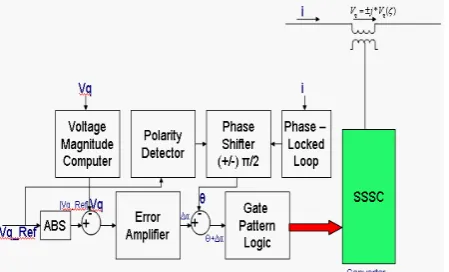
-In order to do this, a compensating voltage Vc of certain amplitude and in quadrature with the line current needs to be injected by the SSSC at the point of connection. The magnitude of the Vc is controlled by the power contro1Ier in closed-loop until the power request is met. The angle of the BVSI voltage with respect to the line current is established by a phase angle controller (-90' or 90') based on whether the compensation required is capacitive or inductive.
The power flowing in the line at the point of the BVSI connection is measured continuously and per-unitized by dividing the measured value to the rated power. The rated power of the line is chosen to represent 1 pu. Thus, every day there is a new power demand in the line above or below 1 pu, the controller responds by calculating an error signal based on the new power demand and the power flowing through the h e at that moment. This error is passed through a proportional plus integral (PI) controller with feedback signal derived from the power measured in the line and the new demand. The output of this PI controller is the modulation index (MI) and depending upon its value, the modulation angles (Bi...&) to fire various switches are selected from the pre-computed switching patterns table.
The sequence of dues for the firing angles (Bi...&) coming out from the switch firing logic are gate signal vectors (sa, sb, s,) for the inverters in the configuration of the 3-level binary VSI. Figure 9 illustrates the phase angle controller used for generating a voltage signal in quadrature with the line current for one phase. Similar schemes are employed for the other two phases, with the corresponding phase shift of 120º.
reference phasor zero. The phase angle of the generated signal is q5 - 90º when the inverter is operated in the capacitive mode, or q5 + 90º for the inductive mode of operation. Also, the phase-shift from the delta configuration in the primary of the coupling transformer to the star connection in the secondary is taken into account and the angle obtained from the capacitor voltage controller is added/subtracted from the calculated voltage phase angle depending on whether the capacitor voltages are above or below the normalized levels. The frequency of the voltage signal is held constant at 60 Hz and synchronized to the supply. The magnitude of the output voltage is controlled by the modulation index (MI) through the PI controller depending upon the desired level of compensation.
VII. R
ESULT ANDD
ISCUSSIONIn this chapter the results of significant power order/load changes and recovery of a system subsequent to various line faults, obtained from the above study. Conclusions are drawn based on the observations made with regard to the operation and utilization of the new SSSC for real power transfer for different intervals of time from 1 to 3 seconds and some of the graphs are presented only for a smaller duration to highlight the important part of the curve. Also, some of the variables are plotted on magnified scales to allow a comparison between the shapes for curves of different order. The test system with two infinite sources at the ends is considered first for examining the effectiveness of the SSSC for real power compensation in both capacitive and inductive modes.
At the beginning of the operation, the two-bus system is transferring a certain amount of real power from one end to the other according to the parameters described in previous chapters. In the normal state 135 MW power is transferred on the line and this amount represents the line operating at 1p u power. The SSSC is disconnected from the system, when no compensation is needed.
Once the system stabilizes to a steady-state (0.4 s), the line is operating at its full capacity. For SSSC, the capacitors (voltages) are initially charged at 2, 4 and 8 kV levels by batteries. Figure presents the results showing the action of SSSC operating in both capacitive (boost) and inductive (buck) modes. At 0.5 seconds the reference power for the line is increased from 1 to 1.5 pu with SSSC connected to the system to provide the required 50% capacitive compensation. It is seen that the power in the line attains the reference value change in less than 0.2 seconds. At 0.1 seconds after the BVSI is connected to the system, the batteries placed across the dc sources are removed and the capacitor voltages are adjusted and maintained in the binary proportion by the capacitor voltage controller which starts operating at the same with the power controller. At 1.5 seconds the power demand is reduced abruptly to 0.5 pu requiring an inductive compensation of 50% from SSSC. To accommodate the power order reduction the phase of the injected voltage by SSSC undergoes 180° phase shift, which is achieved within one cycle as may be observed. Notice that the phase
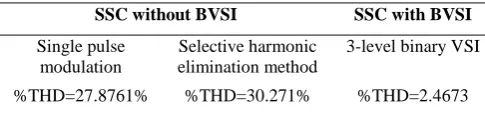
of the current remains unchanged but its magnitude is reduced corresponding to the power level change. It should be observed that the line voltages remain almost unaffected and that the harmonic distortion due to the injection of the 15-step BVSI-SSSC output voltage is practically negligible. A harmonic analysis is performed on the line voltages measured after the point of common coupling and the total harmonic distortion coefficient (THD=2.4673%) proves that a very small percent of harmonies is introduced into the system by the inverter voltage. This result is achieved by the injection of a voltage waveform (Vc) approximating a sinusoidal which
compensates for the drop across the line between the two buses. The phasor of this voltage being perpendicular to the current pharoses at the point of insertion either supplements or annihilates part of the voltage drop taking place in the uniformly distributed reactance of the transmission line. Hence, more or less current is drawn from the sending end since the power angle of the voltage at the intermediate point is either advance or retarded from the original phase shift between the two buses, which remains unaffected by the power changes. Presents similar results when the power order is changed from 0.5 pu to 1.5 pu, switching the SSSC from inductive to capacitive compensation. In both situations, the transition occurs very fast with a rapid phase adjustment in the inverter output within one cycle of the power order change. Compensation of the real power can be achieved at different power orders illustrates a power order step change of 25% in both directions together with the modulation index (MI) values. The modulation angle is calculated continuously based on the actual power need at every instant. Therefore, the variations of the real power flow take place according to the output of the PI controller which produces the MI. It is to be noted that for a higher error in the power controller there is a jump in the value of the MI and as the power in h e approaches the desired value, the MI stabilizes to an almost constant output, thus maintain the level of the compensation. Obviously, the lower the compensation level required, the smaller is the injected voltage. And also, with a smaller step in the power order change, the capacitor voltages are subjected to a smoother variation. Different load changes are study in the second test system with a synchronous machine at the sending-end and the resistive load at the receiving-end. The performance of the SSSC in a more realistic system. After the initialization of the machine the real power flow is 1 pu. At 0.6 seconds another resistive load is switched in at the load bus demanding 50% more real power from the generator. The line is able to increase its transmission capacity but not to the required demand and this happens because the voltage at the load bus (VR) drops below the 1 pu level due to line
the voltage at the load bus increases above 1 pu The inductive compensation is &O effective in providing the exact amount of power to the consumer as well as bringing back the voltage level at the receiving-end. The performance of the SSSC operation under different faults was studied for the test system and the results are presented in figure waveforms for this case show the variations in the fault severity. Figure presents a single-phase to ground fault while the line is transferring 1.1 pu real power being capacitive compensated. At 0.5 seconds a fault occurs in phase A of the transmission line reducing the line voltages Vab and Vac, by 1/√3 and leaving Vbc
unchanged for 5 cycles (80 milliseconds) until the fault is cleared. It is to be observed that due to high fault currents in the capacitors charging leads to transiently high values of Vdc, 2Vdc, and 4Vdc. A few cycles after the fault is
cleared the power in the system is restored and so are the capacitor voltage levels. The total harmonic distortion is calculated at different moments in time after the fault is eliminated.
The THD is found to be less than 3% which should be acceptable as is a two-phase to ground and three-phase to ground fault are simulated next. The results are show. It should be noted that the variation in the dc capacitor voltages are different in the inductive operating mode (when the line power is reduced to 0.9 pu). In case of a fault in a real system, a voltage dependent controller could be added which would detect fault conditions when the line voltages drop bellow a threshold, and disable the SSSC (voltage) controllers to ensure that the capacitors are not subjected to over voltages during the fault and its recovery period. Capacitor overcharging (overvoltage) is observed when the SSSC experiences fault in its capacitive operating mode. Figure shows under voltage when the fault occurs when the SSSC is operating in the inductive mode. The voltage dependent cut-off controller would remedy this under voltage as well and actually speed up recovery.
Table 1: Calculated THD with and without BVSI
SSC without BVSI SSC with BVSI
Single pulse modulation
Selective harmonic elimination method
3-level binary VSI %THD=27.8761% %THD=30.271% %THD=2.4673
Calculation of % THD is carried out using MATLAB for three case 1 and 2 for SSSC without BVSI and 3rdfor BVSI based SSSC. From the above table it has been found that using BVSI based SSSC the total harmonic distortion become very small here %THD is about 2.4673 in comparison to normal VSI based SSSC’s. So we can conclude that BVSI based is better than other classical methods based SSSC.
VIII. C
ONCLUSIONSThe application of BVSI for the control of the real power transferred over high voltage transmission networks has been carried out. In this work a BVSI based SSSC has been fully investigated. The digital simulation results
demonstrate the performance of the BVSI based SSSC as a real power compensator under various operating conditions, in steady-state as under abrupt faults.
1. The low total harmonic distortion proves that the proposed structure of the BVSI and the selected harmonic elimination algorithm are effective in minimization or complete elimination of the harmonies introduced in the system.
2. The BVSI based SSSC can smoothly switch its operating mode from lagging to leading injected voltage with respect to the current phasor at the point of common coupling, effectively providing both series capacitive and inductive compensations on a transmission line.
3. BVSI-SSSC operates robustly as its operation is unaffected by severe line faults. Its recovery from faults is reliable. Therefore from the Tale No. 1, it is clear that, by using BVSI the THD has been minimized over VSI. The proposed BVSI-SSSC offers an alternative to the classical series compensation of lines. In addition it offers controlled compensation and extends the range to inductive compensation as well. The study of the proposed BVSISSSC has been carried out in a simple test system. It should be extended to a complex transmission utility system. Also, the location of the SSSC can be optimized for a network through further studies.
APPENDIX ‘A’
This appendix gives the draft files and data from PSCAD/EMTDC. The first three subsystems represent the initial test system with the two voltege sources at the ends. The transmission line and the BVSI connected are represented together with the measurement functions in the main system. The main controllers (power controller and phase angle controller) are illustrated in the block diagrams of the second subsystem. The third subsystem presents the capacitor voltage controller and the outputs which are used in the main system. The last diagram presents the main system when the sending-end is replaced by the synchronous machine and the receiving-end by the resistive load to which more load is added and also, some load is removed respectively, in order to simulate the load changes at the customer bus. The Controller gains and the Insertion Transformer parameters are given next:
Controller gains
Capacitive compensation Kpp = 1
Inductive compensation Kpp = -1
Tpi(seconds) = 0.1
Capacitive compensation
Kp, Kp1, Kp2, Kp3 = 10, 12, 10, 12
Inductive compensation
Kp, Kp1, Kp2, Kp3 = -10, - 12, - 10,- 12
Tp, Tp1, Tp2, Tp3(seconds) = 0.8, 1.5, 1, 1
Insertion transformer parameters
Transformer Single Phase = 10 MVA
Leakage reactance = 0.1 pu
Magnetizing current = 1%
R
EFERENCES[1] Abdel-Moamen, M.A. Narayana Prasad Padhy, “ Power Flow Control and Transmission Loss Minimization Model with TCSC for Practical Power Networks”, Power Engineering Society General Meeting, 2003, IEEE, Vol.2, 13-17 July 2003, pp 880-884.
[2] A.M. Vural, Student Member, IEEE, and M. Tumay, “Steady State Analysis of Unified Power Flow Controller: Mathematical Modeling and Simulation Studies,” Paper accepted for presentation at 2003 IEEE Bologna Power Tech Conference, June 23-26, Bologna, Italy.
[3] Abdel Moamen M. A, and Narayana Prasad Padhy, “Newton -Raphson UPFC Model for Power Flow Solution of Practical Power Networks with Sparse Techniques,” 2004 IEEE International Conference on Electric Utility Deregulation, Restructuring and Power Technologies (DRPT2004) April 2004 Hong Kong.
[4] Belkacem Mahdad1, Tarek Bouktir2 ,and Kamel Srairi, “The Impact of Unified Power Flow Controller in Power Flow Regulation,” IEEE MELECON 2006, May 16-19, Benalmádena (Málaga), Spain, pp. 1015-1019.
[5] C. R. Foerte-Esquivel, E. Acha, and H. Amhriz-Pbrez, “A Comprehensive Newton-Raphson UPFC Model for the Quadratic Power Flow Solution of Practical Power Networks,” IEEE Trans on Power Systems, Vol.15, NO. 1, February 2000, pp.102-109.
[6] C.R. Fuerte-Esquivel, and E Archa, “Unified power flow controller: a critical comparison, of Newton-Raphson UPFC algorithms in power flow studies,” IEE Pro,.-Gener. Transm. Distrib., Vol. 144, No. 5, September 1997.
[7] C.Angeles-Camacho,and C. R. Fuerte-Esquivel, “A Three Phase UPFC model for Power Flow Control in Unbalanced Transmission Networks,” Cigre Papers, 2001.
[8] C. Angeles-Camacho, E. Acha, and E. Barrios-Martínez, “Three -phase STATCOM Models for Large-scale Newton-Raphson Power FlowStudies,” Power Tech., 20076, IEEE Lausanne, 1-5 July, 2007, pp. 1250-1255.
[9] Ekanayake J.B. and Jenkine N, "A three-level advances static VAR compensator," IEEE Tractions’ on Power Delivery, vol. 11, no. 1, pp. 54G545, January 1996.
[10] Fang Wanliang, and H.W.Ngan, “Extension of Newton Raphson Load Flow Techniques to Cover Multi Unified Power Flow Controllers,” Proceedings of the 4th International Conference on Advances in Power.
[11] Gyugyi L, "Dynamic compensation of ac transmission lines by solid-state synchronous voltage sources," IEEE ~Transaction Power Delivery, vol. 9, no. 2, pp. 904-911, April199.
[12] Gyugyi L, SchauderC.D., and. WilliamsS.L., "The unified power flow controller:A new approach to power transmission control," IEEE Transactions on Power Delivery, vol. 10, no. 2, pp. 1085-1093, April 1995.
[13] Gyugyi L,. Schauder C.D, and . Sen K.K, "Static synchronous series compensator:A solid-state approach to the series compensation of transmission Lines," IEEE Transactions on Power Delivery, vol. 12, no. 1, pp. 406417, January 1997. [14] Gyugyi L, "Dynamic compensation of ac transmission lines by
solid-state synchronous. voltage sources," IEEE Transactions on Power Delivery, vol. 9, no. 2. pp. 904-911, April 1994. [15] GyugyiL, "Unified power-flow control concept for flexible ac
transmission systems,"IEE Proceedings-C, vol. 139, no. 4, pp. 323-331, July 1992.
[16] H. Am briz-Perez E.Acha C.R. Fuerte-Esquivel A.De la Torre, “Incorporation of a UPFC model in an Optimal Power Flow Using Newton’s method,” IEE Proc.-Gener. Transm. Distrib., Vol. 145, No. 3, May 1998
[17] Hatziadoniu C.J. and ChalkiadakisF.E., "A 12-pulse static synchronous compensator for the distribution system employing the 34evel GTO-inverter," IEEE Transactions on Power Delivery, vol. 12, no. 4, pp. 1830-1835, October 1997.
[18] Juan Segundo and Aurelio Medina, Senior Member, “Periodic Steady- State Solution of Electric Systems Including UPFCs by Extrapolation to the Limit Cycle,” IEEE Trans on Power Delivery, Vol. 23, No. 3, JULY 2008, pp. 1506-1512.
[19] Joshi A, Dubey G.K., Doralda S.R. and Sinha R.M.K, Thyristore Power Controllers, John Wdey & Sons, 1986. [20] Kumar, G.R.; Rao, R.K.; Ram, S.S.T., Power Flow Control and
Transmission Loss Minimization model with TCSC and SVC for Improving System Stability and Security” Industrial and Information Systems, 2008. ICIIS 2008. IEEE Region 10 and the Third international Conference on 8-10 Dec. 2008 Page(s):1 - 5. [21] Krishnamurthy K.A. "Selective reduction of harmonies in
inverters," International Journal of Electronics, vol. 46, pp. 321-330, 1979.
[22] Kumar, G.R.; Rao, R.K.; Ram, S.S.T., Power Flow Control and Transmission Loss Minimization model with TCSC and SVC for Improving System Stability and Security” Industrial and Information Systems, 2008. ICIIS 2008. IEEE Region 10 and the Third international Conference on 8-10 Dec. 2008 Page(s):1- 5. [23] Kundur Prabha, Power System Stability and Control,
McGraw-EW, Inc., 1994.
[24] Miller T.J.E., Guide for Economic Evaluation of FACTS in Open Access Environments, John Wiley & Sons, 1982. [25] M.O. Hassan, S. J. Cheng , and Z. A. Zakaria, “ Steady-state
Modeling of SVC and TCSC for Power Flow Analysis,” Proceedings of International Multi Conference of Engineering and Computer Scientists 2009, Vol. II,IMECS2009,March 18-20, 2009, Hong Kong.
[26] Norberto Garcia, “Parallel Harmonic-Oriented Method for Large-Scale Electric Systems Based on MPI Programming and
the Limit Cycle Method,” Power Tech., 2005, IEEE Russia, 27 -30 June, 2005, pp. 1-6.
[27] Patil K.V., Mathur R.M, Jiang J., and S.H. Hosseini S.H., "Distribution system compensation using a new binary multi level voltage source inverter," IEEE Transactions on Power Delivery, vol. 14, no. 2, pp. 459-464, April 1999.
[28] Patil Krishnat V. Dynamics Compensation of Electrical Power System wing a new BVSI STATCOM, Ph.D. thesis, Electrical and Computer Engineering, University of Western Ontario, March 1999.
[29 Patil K.V., Mathur LM., Jiang J., and Hosseini S.H., "Distribution system compensation using a new binary multilevel voltage source inverter," IEEE Transactions
[30] Sen K.K., ''SSSC static synchronous series compensator: Theory modeling and applications," IEEE ~ transaction Power Deliver, vol. 13, no. 1, pp. 241-246, January 1998.
[31] Sahoo, Ashwin Kumar, Dash S.S., and Thyagarajan, T.,
“Modeling of STATCOM and UPFC for power system steady state operation and control” Information and Communication Technology in Electrical Sciences (ICTES 2007), 2007. ICTES. IET-UK International Conference on 20-22 Dec. 2007 Page(s):458–463.
[32] Samina Elyas Mubeen, R. K. Nema , and Gayatri Agnihotri, “Power Flow Control with UPFC in Power Transmission System,” Proceedings of World Academy of Science, Engineering and Technology, Volume 30, July 2008, pp. 955-959.
[33] Suman Bhowmick, Biswarup Das, Senior Member, and Narendra Kumar, “An Indirect UPFC Model to Enhance Reusability of Newton Power-Flow Codes,” IEEE Trans on Power Delivery, Vol. 23, No. 4, October 2008, pp.2079-2088. [34] Samina E. Mubeen, R. K. Nema, and Gayatri Agnihotri,
“Comparison of Power flow control: TCSC versus UPFC,” Power System Technology & IEEE Power India Conference 2008, POWERCON- 2008, 12-15 October 2008, pp. 1-5. [35] Venegas T., Fuerte-Esquivel, C.R. “Steady-State Modelling Of
Thyrister Controlled Series Compensator For Phase Domain Load Flow Analysis Of Electric Network”, Electric Utility Deregulation and Restructuring and Power Technologies, 2000. Proceedings. DRPT 2000. International Conference, 4-7 April 2000 Page(s):191–196.
[37] Wenjin Dai, and Zhihong Liu, “Study on Modeling of Unified Power Flow Controller,” Proceedings of the IEEE International Conference on Automation and Logistics, August 18 - 21, 2007, Jinan, China.
[38] Xiao-Ping Zhang, and Keith R Godfrey, “Advanced Unified Power Flow Controller Model for Power System Steady State Control,” 2004 IEEE International Conference onElectric Utility Deregulation, Restructuring and Power Technologies (DRPT2004) April 2004 Hong Kong.
A
UTHOR’
SP
ROFILEEmad Ali Daood
born on 6thOct. 1967 in Iraq. He has completed B. Sec. in Electrical Engineering from University of Baserah, Iraq. Presently he is working as Asst. Lecture in Electrical Department Branch Power in Technical Institute Basarah, Iraq.
Email: [email protected]
K. Verma
EE Department, SHIATS-DU, Allahabad-India
Surya Prakash
belongs to Allahabad, DOB is 01.05.1971, Received his Bachelor of Engineering degree from The Institution of Engineers (India) in 2003, He obtained his M.Tech. in Electrical Engg.(Power System) from KNIT, Sultanpur. UP-India in 2009. Presently he is Pursuing Ph.D. in Electrical Engg. (Power System), SSET, HIATS (Formerly Allahabad Agriculture Institute, Allahabad- India). His field of interest includes power system operation & control, Artificial Intelligent control.