ISSN : 2581-7175 ©IJSRED: All Rights are Reserved Page 516
Design and Implementation of Solar Powered Automatic Sprinkler
Irrigation System
Isizoh A.N*, Nwankwo P.N**, Onwuzulike D.A***, Chukwuemeka G.F****
*(Department of Electronic and Computer Engineering, Nnamdi Azikiwe University Awka, Anambra State, Nigeria Email: [email protected])
** (Department of Computer Engineering; Federal Polytechnic Oko, Anambra State, Nigeria Email: [email protected])
***(Department of Computer Engineering; Federal Polytechnic Oko, Anambra State, Nigeria Email: [email protected])
**** (Department of Electronic and Computer Engineering, Nnamdi Azikiwe University Awka, Anambra State, Nigeria Email:[email protected])
---
************************
---Abstract:
In the field of Agriculture, the importance of automatic irrigation control system cannot be overemphasized. The project presents the design and implementation of “Solar Powered Automatic Sprinkler Irrigation System” that irrigates a farm by switching a DC water pump based on the set- time and the time interval programmed into the microcontroller. The designed system replaces the conventional manual process involved in sprinkler irrigation to automatic process; to conserve energy, time, and water. The aim of the project is to improve on water management in irrigation process, and minimize the intervention of human operator in irrigation activities in farms. The system was designed with various components like; AT89C51 microcontroller, Dc water pump, Relay, LCD and other electronic components. The whole system was built around the AT89c51 microcontroller. The microcontroller was programmed using assembly language. When the set time is reached, the microcontroller triggers a 12v relay which automatically drives the DC water pump for 3 minutes. The irrigation takes place by 7am and 7pm daily to achieve the desired result. Input is given to the microcontroller in the form of time using the keypad. An LCD is interfaced with the microcontroller to display the system status. The 12v, 130watts Monocrystalline solar panel and the 60AH deep cycle (solar) battery attached to the system provides all the energy requirements of the system. The system has proven to be a reasonable advancement in irrigation system.
Keywords: Automatic Irrigation System, Microcontroller, Solar Energy, Assembly Language Programming, Liquid Crystal Display (LCD).
---
************************
---1. INTRODUCTION:
The continuous increase in food demand requires a rapid improvement in food production technologies. Food insecurity is a major challenge in developing countries. Irrigation has been used to
assist in the growing of Agricultural crops, maintenance of landscapes, and re-vegetation of disturbed soils in dry areas and during periods of inadequate rainfall [1]. Irrigation is the process of artificial application of water to land to aid crops growth. It is mainly used during dry seasons or in dry areas where rainfall is scarce. An automatic
ISSN : 2581-7175 ©IJSRED: All Rights are Reserved Page 517
irrigation system presents the most efficient convenient and cost effective way to irrigate the landscape and stimulate lush greenery all around [2]. Proper designing and maintaining both the irrigation system and irrigation valves is important as more than 60% of wasted water due to poorly designed installed and operated sprinkler systems. The old method used for irrigation was the use of watering cans, water channels that have to be opened and closed manually or backpack sprinklers. In this case, a lot of water is wasted in the process [3]. There is need for improvement on the existing or old forms of irrigation. An automated irrigation system needs to be developed to optimize water use for Agricultural crops. Automatic irrigation is a form of irrigation system that is operated by a computerized controller. This type of system is ideal for those who travel frequently and cannot attend to their lawns on a regular basis. It is also convenient and highly practical for those who have farms and large landscape areas. As the name implies; the system is powered by solar energy for optimum performance.
A. Problem statement
Over the last decades, empirical experience has shown that irrigation increases yield of most crops by between 100 and 400%. It is expected that, over the next 20-25 years, 70% of the grain production will be from irrigated land in the world. The Food and Agriculture Organization estimates that irrigated land in developing countries will increase by 27%t in the next 20 years, but the amount of water expected to be available for agricultural production will only increase by a mere 12%. The available water resource for irrigation has to be put to optimal use through appropriate technology.
B. Aim of the Project
This project aims at automating irrigation systems using a micro-controller to improve on water management. This will minimize the intervention of human operator in irrigation activities in farms, increase yields, improve crop
quality, and most importantly conserve water, thus saving money.
C. Objectives of the Project
The main objective of this project is to keep measure on food security.
General objectives;
1. Recognize the need for water saving in irrigation systems.
2. Use microcontroller to switch ON Dc water pump every 7AM and 7PM for 3 minutes.
3. Reduce the number of workforce in the farm. 4. Improve our immediate environment by using sustainable energy solution (solar energy).
II. METHODOLOGY:
The automatic irrigation system was designed to continuously water the soil based on a given time interval (3 minutes) every 7AM and 7PM. The system responds appropriately by watering the soil with the required amount of water and then switching off the DC water pump automatically by deactivating the actuator (relay) when the given time interval has elapsed.
A. System Block Diagram
ISSN : 2581-7175 ©IJSRED: All Rights are Reserved Page 518
XT AL2 18
XT AL1 19
ALE 30
EA 31
PSEN 29
RST 9
P0.0/AD0 39 P0.1/AD1 38 P0.2/AD2 37 P0.3/AD3 36 P0.4/AD4 35 P0.5/AD5 34 P0.6/AD6 33 P0.7/AD7 32
P1.0 1
P1.1 2
P1.2 3
P1.3 4
P1.4 5
P1.5 6
P1.6 7
P1.7 8
P3.0/RXD 10 P3.1/T XD 11 P3.2/INT0 12 P3.3/INT1 13 P3.4/T0 14
P3.7/RD 17 P3.6/WR 16 P3.5/T1 15 P2.7/A15 28 P2.0/A8 21 P2.1/A9 22 P2.2/A10 23 P2.3/A11 24 P2.4/A12 25 P2.5/A13 26 P2.6/A14 27 U1
AT89C51 2 X 16 LCD
E R/W RS
89C51 12V VCC
RV1
1k Fig.1: Block Diagram of the solar powered automatic sprinkler irrigation
system
The system is divided into five units; • The Display Unit
• The Actuator/ Dc Pump Unit • The key pad unit
• The microcontroller unit • The power supply unit
B. The Display Unit
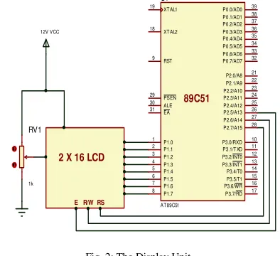
Liquid Crystal Display (LCD) screen is an electronic display module and find a wide range of applications. A 16x2 LCD display is the most common module and is very commonly used in various devices and circuits. These modules are preferred over seven segment displays and other multi segment LEDs. The reasons being; LCDs are economical, have no limitation of displaying special and even custom characters (unlike in seven segments), animations and so on [4]. A 16x2 LCD means it can display 16 characters per line and there are 2 such lines. In this LCD each character is displayed in 5x7 pixel matrix. The LCD has two registers; Command and Data. The command register stores the command instructions given to the LCD. A command is an instruction given to LCD to do a predefined task like initializing it, clearing its screen, setting the cursor position, controlling display etc. The data register stores the data to be displayed on the LCD. The data is the ASCII value of the character to be displayed on the
LCD. The LCD is used to display the status of the system. LCD to microcontroller interface is shown in fig. 2 below.
Fig. 2: The Display Unit
C. The Actuator/ Dc Pump Unit
ISSN : 2581-7175 ©IJSRED: All Rights are Reserved Page 519 XTAL2 18 XTAL1 19 ALE 30 EA 31 PSEN 29 RST 9 P0.0/AD0 39 P0.1/AD1 38 P0.2/AD2 37 P0.3/AD3 36 P0.4/AD4 35 P0.5/AD5 34 P0.6/AD6 33 P0.7/AD7 32 P1.0 1 P1.1 2 P1.2 3 P1.3 4 P1.4 5 P1.5 6 P1.6 7 P1.7 8 P3.0/RXD 10 P3.1/TXD 11 P3.2/INT0 12 P3.3/INT1 13 P3.4/T0 14 P3.7/RD 17 P3.6/WR 16 P3.5/T1 15 P2.7/A15 28 P2.0/A8 21 P2.1/A9 22 P2.2/A10 23 P2.3/A11 24 P2.4/A12 25 P2.5/A13 26 P2.6/A14 27 U1 AT 89C51 R2 0R1 R3 0R1 R4 0R1 12V VCC 89C51
Fig. 3: (a) Relay in ON position (b) Relay in OFF position (c) Physical structure of a Relay
This unit comprises of the biasing resistor R5, 12v relay, Transistor and the DC pump. The Resistor R5 limits the current that passes through the base of the transistor. When the set time for the irrigation is reached (7AM and 7PM), the microcontroller sends logic 1 (high signal) to p0.0 and the transistor is forward biased, hence, triggering the relay; which automatically switch ON the DC water pump for the irrigation process. When the time interval for the irrigation elapses (3-minutes), the microcontroller sends logic 0 (low signal) to p0.0 to deactivate the transistor, causing the transistor to be reverse biased, thus; deactivating the relay and disconnecting the DC water pump to stop the irrigation process. The microcontroller, relay and DC water pump interface are shown in fig. 4 below.
XT AL2 18 XT AL1 19 ALE 30 EA 31 PSEN 29 RST 9 P0.0/AD0 39 P0.1/AD1 38 P0.2/AD2 37 P0.3/AD3 36 P0.4/AD4 35 P0.5/AD5 34 P0.6/AD6 33 P0.7/AD7 32 P1.0 1 P1.1 2 P1.2 3 P1.3 4 P1.4 5 P1.5 6 P1.6 7 P1.7 8 P3.0/RXD 10 P3.1/T XD 11 P3.2/INT0 12 P3.3/INT1 13 P3.4/T0 14 P3.7/RD 17 P3.6/WR 16 P3.5/T1 15 P2.7/A15 28 P2.0/A8 21 P2.1/A9 22 P2.2/A10 23 P2.3/A11 24 P2.4/A12 25 P2.5/A13 26 P2.6/A14 27 U1 AT 89C51 12V VCC Q1 2N1711 89C51 RL1 QUAZ-SH-112D R5 1k
Fig.4: The Actuator/ DC Pump Unit
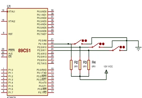
D. The Keypad Unit
For the keypad, a momentary touched switch was used. The resistors (R2=R3=R4 =1kΩ) are pulled up to positive supply (vcc) to boost the signal at the respective pins of the microcontroller were the switches are connected. The switches are used to set the time and the time interval for the irrigation. The keypad and the microcontroller interface is shown in fig. 5 below.
Fig. 5: The Keypad Unit
E. The AT89C51 Microcontroller:
ISSN : 2581-7175 ©IJSRED: All Rights are Reserved Page 520 XTAL2 18 XTAL1 19 ALE 30 EA 31 PSEN 29 RST 9 P0.0/AD0 39 P0.1/AD1 38 P0.2/AD2 37 P0.3/AD3 36 P0.4/AD4 35 P0.5/AD5 34 P0.6/AD6 33 P0.7/AD7 32 P1.0 1 P1.1 2 P1.2 3 P1.3 4 P1.4 5 P1.5 6 P1.6 7 P1.7 8 P3.0/RXD 10 P3.1/TXD 11 P3.2/INT0 12 P3.3/INT1 13 P3.4/T0 14 P3.7/RD 17 P3.6/WR 16 P3.5/T1 15 P2.7/A15 28 P2.0/A8 21 P2.1/A9 22 P2.2/A10 23 P2.3/A11 24 P2.4/A12 25 P2.5/A13 26 P2.6/A14 27 U1 AT89C51
Fig. 6: The AT89C51 Microcontroller
F. The Solar Power Unit
Light (photons) striking certain compounds, in particular metals, causes the surface of the material to emit electrons. Light striking other compounds causes the material to accept electrons [8]. It is the combination of these two compounds that can be made use of to cause electrons to flow through a conductor, and thereby create electricity. This phenomenon is called the photo-electric effect. Photovoltaic means sunlight converted into a flow of electrons [9].
The Solar charge controller is used to regulate the rate at which electric current flows into the battery. It prevents overcharging and protect against over voltage, which can reduce the life span of the battery. 7805v (+5v) regulator is used to regulate the +12v from the battery to +5v suitable to power the microcontroller and other electronic components of the system. The block diagram of the Solar Power Unit is shown in fig. 7 below.
Fig. 7: Solar Power Unit of the System
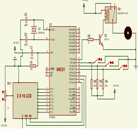
G. The Complete Circuit Diagram
The complete circuit diagram of the solar powered automatic sprinkler irrigation system is shown in fig. 8 below. The AT89c51 microcontroller onboard the system is used to store the entire assembly language program needed for the system to function appropriately.
XTAL2 18 XTAL1 19 ALE 30 EA 31 PSEN 29 RST 9 P0.0/AD0 39 P0.1/AD1 38 P0.2/AD2 37 P0.3/AD3 36 P0.4/AD4 35 P0.5/AD5 34 P0.6/AD6 33 P0.7/AD7 32 P1.0 1 P1.1 2 P1.2 3 P1.3 4 P1.4 5 P1.5 6 P1.6 7 P1.7 8 P3.0/RXD 10 P3.1/TXD 11 P3.2/INT0 12 P3.3/INT1 13 P3.4/T0 14 P3.7/RD 17 P3.6/WR 16 P3.5/T1 15 P2.7/A15 28 P2.0/A8 21 P2.1/A9 22 P2.2/A10 23 P2.3/A11 24 P2.4/A12 25 P2.5/A13 26 P2.6/A14 27 U1 AT89C51 X1 CRYSTAL C2 30PF C3 30PF 12V VCC C1 10uF R2 0R1 R3 0R1 R4 0R1 12V VCC 12V VCC Q1 2N1711
2 X 16 LCD
E R/W RS
89C51 12V VCC RL1 QUAZ-SH-112D R1 10k R5 1k RV1 1k
ISSN : 2581-7175 ©IJSRED: All Rights are Reserved Page 521
H. Working of the System:
Basically, from our preliminary knowledge in Agriculture, it is known that irrigation is normally done in the early hours of the day and in the late hours of the night. Hence with this fundamental concept the system was designed such that irrigation takes place by 7am in the morning and 7pm in the night for optimum performance. When the set time is reached, the microcontroller triggers a 12v relay which automatically drives the DC water pump for 3-minutes before going off. This process is repeated two times daily (7am and 7pm). Since the solar panel cannot function optimally at the time chosen, hence a 12v DC battery is incorporated in the design to store electric charges. During the day when the intensity of the sun is much, the solar panel charges the battery, which can be used at night (7pm) and in the morning (7am) for the irrigation process. The designed system replaces the conventional manual work involved in sprinkler irrigation to automatic process. Using this system a farmer is protected against adverse inhuman weather conditions. Also the system conserves energy, time, and water.
III. SOFTWARE DESIGN
To be able to control, coordinate, monitor, and manage the whole activities of the system, the microcontroller was used. Assembly language was used to program the microcontroller. The PM-51 Macro Assembler was used for this project. The term PM-51 belongs to an entire family of single-chip microcomputers, all of which have the same processor design. They use the same instruction set, but differ slightly in Memory mapped special function registers (SFRs) and on-chip ROM and RAM. The assembler is a software tool, a program designed to simplify the task of writing computer programs. It performs the clerical task of translating symbolic code into executable object code.
A. Pseudo-code of the System
Pseudo-code is a detailed yet readable description of what a computer program or algorithm must do, expressed in a formally-styled natural language rather than in a programming language. Pseudo-code is sometimes used as a detailed step in the process of developing a program. It allows designers or lead programmers to express the design in great detail and provides programmers a detailed template for the next step of writing code in a specific programming language [10]. Catching errors at the pseudo-code stage is less costly than catching them later in the development process. The Pseudo-code of the Solar Powered Automatic Sprinkler Irrigation System is shown below:
The Pseudo-Code of the Designed System:
Step 1: Start
Step 2: Initialize the Ports and Pins of the Microcontroller
Step 3: Send message 1 “SOLAR IRRIGATION SYSTEM”
Step 4: Process Message 1 Step 5: Display Message 1
Step 6: Send Message 2 “IRRIGATION FARM AT 7AM AND 7PM DAILY”
Step 7: Process Message 2 Step 8: Display Message 2 Step 9: Send Message 3 “Time” Step 10: Process Message 3 Step 11: Display Message 3
Step 12: Check if the Required Time is Set? • If NO - Set time, Move to Step 13 • IF YES – Move to Step 13
Step 13: Increment Time every Second Step 14: Is Time 7AM or 7PM?
• IF NO - Go back to Step 13 • IF YES – Move to Step 15
Step 15: Start DC water Pump to Irrigate for 3 minute, Then Go Back to Step 12
Step 16: END
ISSN : 2581-7175 ©IJSRED: All Rights are Reserved Page 522
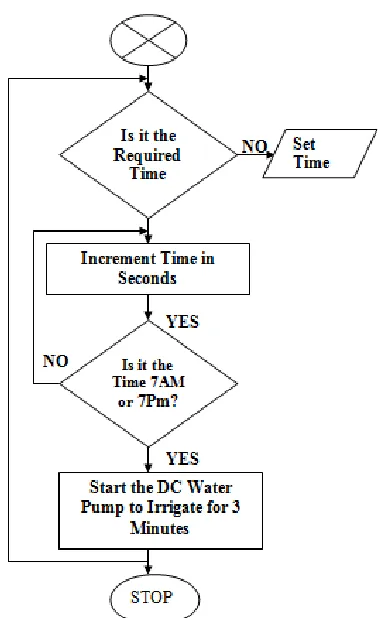
A flow chart is a graphical or symbolic representation of a process. Each step in the process is represented by a different symbol and contains a short description of the process step. The flow chart symbols are linked together with arrows showing the process flow direction [11].
Common Flowchart Symbols:
Different flow chart symbols have different meanings. The most common flow chart symbols are:
• Terminator: An oval flow chart shape indicating the start or end of the process. • Process: A rectangular flow chart shape
indicating a normal process flow step. • Decision: A diamond flow chart shape
indication a branch in the process flow. • Connector: A small, labelled, circular flow
chart shape used to indicate a jump in the process flow.
• Data: A parallelogram that indicates data input or output (I/O) for a process.
• Document: Used to indicate a document or report.
The Flow Chart of the Solar Powered Automatic Sprinkler Irrigation System is shown in fig. 9 below.
STATE
Send Message 1 Initialize Ports & Pins
Process Message 1
Display Message 1
Send Message 2
Process Message 2
Display Message 2
Process Message 3 Send Message 3
ISSN : 2581-7175 ©IJSRED: All Rights are Reserved Page 523
Fig. 9: Complete Flow Chart of the Solar Powered Automatic Sprinkler Irrigation System
IV. CONCLUSION & RECOMMENDATION
A. Conclusion
The “Solar Powered Automatic Sprinkler Irrigation System” was implemented and found to be feasible and cost effective. It is advantageous over manual control as it uses time-based control mechanism. The system was carried out considering some factors which includes; availability of components, economic applications, controllability, durability, and free energy from the Sun. The system after completion; was tested and it met the expected design specification and performance. The project presents a model to modernize the agriculture industries at a mass scale with optimum expenditure. Using this system, one
can save manpower and water to improve production and ultimately profit.
B. Recommendations
To improve on the effectiveness and efficiency of the system the following recommendations can be put into consideration:
1. SMS/GSM technology can be used such that whenever the water pump switches ON/OFF (during and after irrigation) an SMS is sent to the farm attendant mobile phone.
2. The pump should be controlled via GSM, from any location within the country.
3. The system can be integrated with temperature and humidity sensors to monitor the weather conditions in the farm.
REFERENCES:
[1]. Pavithra D.S, Srinath M.S “GSM based automatic irrigation control system for efficient use of resources and crop planning by using an Android mobile” IOSR Journal of Mechanical and Civil Engineering Volume 11, Issue 4 Ver.1 July-August 2014 p. 49-55.
[2] Archana P, Priya R, “Design and Implementation of Automatic Plant Watering System”, International Journal of Advanced Engineering and Global Technology Vol-04, Issue-01, January 2016, ISSN No: 2309-4893. [3] Abhinav Rajpal, Sumit Jain, Nistha Khare & Anil Kumar Shukla , (2011) “Microcontroller-based Automatic Irrigation System with Moisture Sensor” Proceedings of the International Conference on Science/Engineering . [4] Nwankwo Nonso Prince, Alumona Theophilus, Nwankwo Vincent, Nwokeke .O. Albert, (2014), “Design and Implementation of Microcontroller Based Automatic Fan Speed Regulator (using temperature sensor)” Proceedings of the International Journal of Engineering Research and Management (IJERM).
[5] Nwankwo, P. N, (2017), 8051/8951 Microcontroller: Instruction formats, Assembly Language, and Hardware Interfacing, Awka, Benzero Grapfix, pg 125-126.
[6] Nwankwo, P. N, (2017), “8051/8951 Microcontroller: Instruction formats, Assembly Language, and Hardware Interfacing”, Awka, Benzero Grapfix, pg 80-83.
[7] Isizoh .T, Nzeribe. H.N, Aniedu. A, (2018), “Assembly Language Programming: For Embedded Systems and Real – Time Applications”, Awka, SCOA Heritage Nig. Ltd, pg 27-28.
[8] Merteno R., "Hybrid Thermal Photovoltaic Systems”, (2012), Photovoltaic Solar Energy Conversion Conference (C21), Royal Society, pp. 60-62.
[9] Dixon A.E., Leslie J.D, (2006) “Solar Energy Conversion”, Pergamon Press New York, pp. 35-37.