doi: 10.11648/j.ajwse.20180402.11
ISSN: 2575-1867 (Print); ISSN: 2575-1875 (Online)
Research and Construction Control Points of Vertical
Jacking Technology of Water Diversion Tunnel
Sha Junqiang
State Grid Jiangsu Electric Power Engineering Consulting Co. Ltd, Nanjing, China
Email address:
To cite this article:
Sha Junqiang. Research and Construction Control Points of Vertical Jacking Technology of Water Diversion Tunnel. American Journal of Water Science and Engineering. Vol. 4, No. 2, 2018, pp. 16-22. doi: 10.11648/j.ajwse.20180402.11
Received: June 2, 2018; Accepted: June 19, 2018; Published: July 21, 2018
Abstract:
Taking the circulating water diversion tunnel project of a large power plant as an example, a new type of underground excavation technology, namely vertical jacking construction technology was studied. The reaction force of the bottom of the tunnel was calculated accurately by establishing the calculation model, and the countermeasures to overcome the reaction force were put forward. At the same time, the vertical jacking process, control points and monitoring content were discussed. Through the above research and analysis, it can provide reference and help for the construction of similar projects, and promote the further development of the technology.Keywords:
Water Diversion Tunnel, Vertical Jacking, Reaction Force Calculation, Split Grouting, Opening Degree Monitoring1. Preface
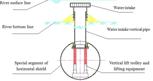
The vertical jacking construction technology of the diversion tunnel is a new kind of underground excavation technology. In the construction of the diversion tunnel, it uses the shield method to drive the diversion trunk pipeline into the soil layer of a certain depth of the river, lake and seabed, Then take the bottom of special section of the shield head (generally steel and steel concrete composite structure) as rear support of
vertical jacking,A special vertical jacking device is installed. Through this equipment, the segmented prefabricated water intake pipe is raised in the vertical direction from the hole in the upper part of the special section of the shield. The vertical pipe passes through the overlay and into the water body, then the water intake is installed to collect water. The vertical pipe is generally square and can be set up along the horizontal shield head according to the amount of water taken. The schematic diagram is shown in Figure 1.
The vertical jacking construction technique is mainly used for the area of large water intake, gentle bottom line and easy silting. With the increase of water intake and the decreasing of high quality water intake, the application of this technology will be more and more extensive. However, there are still a lot of risks and weak points in the application of this technology, so it is necessary to study and analyze and take reliable technical measures to ensure the safety of construction process. Taking water tunnel project of a large power plant as an example, this paper analyzes and studies the technology.
2. Project Overview
The water intake system of 2×1000MW unit in a power plant mainly includes 1 blocks of circulating water pump house, 2 of diversion tunnels and 14 vertical pipes. The circulating water pump room is located on the inner side of the Yangtze River Dike, about 12 meters from the dike of the Yangtze River, and about 25 meters from the slope angle. The diversion tunnel begins in the north inlet of the circulating water pump house (also as a working shaft for the diversion tunnel construction), After crossing the Yangtze River Dike, it extends to about 870m in the Yangtze River, its inner diameter is φ4.2 meters, the outside diameter is Φ4.8 meters, uses shield method construction, the single water tunnel projection length is about 943.2 meters; 14 vertical pipe are set up at the end of the tunnel, 14 water intakes is installed at the top of the
vertical pipe. Two water intake tunnels have the same elevation, and the axes are distributed parallel in space. 3.12 m/s is the maximum velocity of flow in the section of the project. The center elevation of the entrance of the diversion tunnel is -7.9m, after which the shield is as follows: I start straight line segment 30 ring, slope i =0.018; II right curved arc section 240 ring, slope i=0.018; III middle straight segment, 275 ring, slope i=0.018; IV left curved arc section 240 ring, slope i=0.018; V Intermediate straight segment 30 ring, slope i=0.018; VI vertical arc Section 50 ring, slope i=0~0.018; VII horizontal straight segment 134 ring, slope i =0; VIII vertical rise section 49 ring, horizontal straight line segment. The tunnel end center elevation is -21.50m. The horizontal arc curve is r=2500.00m, the vertical arc curve is r=2500.00m. The tunnel segment includes two types: standard section and special section. The standard section is made of reinforced concrete, and the special section is made of steel and steel concrete composite. the special section are used in the vertical lifting section at the end of the intake tunnel. A vertical jacking hole is reserved on the upper part of the steel and steel concrete composite segments, and is sealed by steel sealing doors. The water intake pipe is a precast square concrete pipe with a plane dimension of 1.80 m×1.80 m and the thickness of the pipe wall is 180 mm. Each pipe is made up of 13 sections, the top of the pipe is -7.664 m. As shown in Figure 2.
Figure 2. Schematic diagram of diversion system of Engineering.
3. The General Situation of Engineering
Geology
The shield is mainly through three soil layers, in which the vertical vertical jacking is mainly through the IV soil layer, and the local III layer is sandwiched. Soil characteristics, burial conditions and physical and mechanical properties of the indicators are as follows:
III silty soil of soil layer: gray, saturated, silt, slightly dense to medium density, mainly quartz, feldspar and mica; silty soil is slightly dense, silt and silt appear in the form of interlayer.
The water generally distribute in the 380m range of the dyke, and then fade to the heart of the river. The thickness is 3.8 m. The tip resistance qc is 4.3MPa and the sidewall friction resistance is 50kPa.
IV mucky silty clay of soil layer: gray, soft plastic and uneven soil, visible horizontal bedding, thin layer silt and silt, with strong thixotropy, the typical soft soil of the site, the thickness of soil layer is 7 m. The tip resistance qc is 0.7MPa and the sidewall friction resistance is 10kPa.
dense, more lens body output, soil thickness of 7 m. The tip resistance qc is 0.7MPa and the sidewall friction resistance is 10kPa.
4. Engineering Features and Difficulties
1) One of the difficulties of vertical jacking technology is the establishment of vertical jacking force calculation model and the selection of various parameters. Because jacking up to push vertically (empty-push) and cross the soil layer and water body, there are many factors affecting the jacking force, and the interaction relationship is complex. If the calculation model is unreasonable or inaccurate, it may result in failure of jacking up or damage to the bottom of horizontal shield segment [1].
2) Vertical jacking operating surface located at the bottom of the Yangtze River -21.50 m deep, when the water pressure is raised, its huge force is in the bottom of the horizontal shield segment, if the bottom segment deformation is too large, leakage between shield segments, under the water pressure of 20 meters, water and silt will rapidly into the tunnel, the consequences of unimaginable.
3)When the vertical top head pipe is jacking from the top of the horizontal shield, the seal of the vertical pipe section and the upper part of the horizontal shield must be safe and reliable, and bear the water pressure above 20 m.
4) Because the distance between the vertical pipes of the water intake is close, the vertical pipe in the following construction will have a big extrusion effect on the finished vertical pipe on both sides. If the control is not properly controlled, the vertical pipe which has been completed will be squeezed and even damaged.
5)The control of vertical pipe perpendicularity should take
into account the friction resistance between the vertical jacking pipe joint and the reserved hole, which has a great relationship with the size of the clearance and the vertical degree of the vertical pipe, such as the excessive clearance or the vertical deviation of the vertical pipe, which will lead to the problems of the vertical pipe jamming, clearance leakage and so on.
5. Construction Technical Measures and
Plans
5.1. Calculation of Back Force at the Bottom of a Tunnel with Vertical Jacking Section
When the vertical pipe is jacking up, the bottom of the tunnel will be affected by the local concentrated load. The load value is mainly the maximum lift of the shear soil and the sum of the weight of the trolley, without calculating the friction between the jacking pipe joint and the reserved hole.
After several simulation, analysis and discussion, and referring to the related paper [2, 3], the calculation model and various parameters of soil shear failure are determined. The calculation process is as follows:
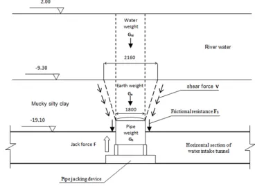
Assuming that the head width of the pipe jacking is D, the top of the soil in the shear failure line is calculated by 1.2D-1.5D. The top force of the jacking F needs to overcome the water weight above Gw, the self weight of the pipe Gs, the
weight of the soil weight Ge, the shear force V between the pipe and the soil, and the friction resistance Fs of the soil around the pipe joints, after the top into the Yangtze River, the influence of the flow velocity should also be taken into account. As shown in Figure 3.
Then the formula for calculating vertical top force is as follows:
F=Gw+Gs+Ge+V+Fs (1)
For the above parameters, the highest tide level is 1.96m when the frequency P is 1% during the jack up operation, and the 2.00m is calculated in the calculation. The water weight is Gw=684 kN, and the pipe weighs Gs=270 kN. At the beginning of the jacking, V=2559 kN, FS=0 kN. bring the
calculation results into (1), F=3574 kN. The weight of the trolley is calculated at 150 kN. Without considering the friction between the steel pipe and the jacking pipe, the top force of the shield segment is 3724 kN.
Through the mathematical analysis and field simulation test, there is no friction between the longitudinal pipes, and the friction force exists between the annular pipes because of the effect of soil and water pressure, and the friction force (f) is calculated as follows.
f=q×∆S×k (2)
In the formula:
q--Soil and water pressure. ∆S-- Effective area of force.
k-- Friction coefficient between steel pipe sheets.
The relevant parameters are substituted (2), and the soil and water pressure is taken as the simulated measured value, so f=175 kN.
Because of the two contact surfaces of the ring segments, the friction force during the jacking process ft=350 kN.
Based on the above calculation and analysis, the maximum reaction force at the bottom of the segment during jacking is 4074 kN.
According to the calculation results, 6 specifications of 100t hydraulic jack are selected as the main oil cylinder.
According to the geological survey report, there may be a hard layer of powder sand sandwiched in the vertical jacking area, the tip resistance of the soil layer reaches 4.3MPa, and the friction resistance of the side wall reaches 50kPa. For a vertical pipe that needs to cross the third hard soil layer, the 30MPa high pressure water jet can be used to destroy the jacking path and the hard soil layer within a certain range, and
reduce the resistance [4]. High pressure water rotary jet using water operating ship construction, should pay attention to control the timing of the jet, generally in 3-5 days before vertical jacking, if early implementation, the damaged soil after a long period of deposition, but will increase the resistance.
When the path of the jacking riser meets undiscovered stones, wood and other debris, it can be digged from the water by precise positioning.
5.2. Reinforcement Measures and Control Points for Coping with Counterforce
After the equipment is selected, the most important problem is to overcome the reaction force acting on the bottom of the shield when jacking up. According to the results of the previous section, the counterforce at the bottom of the shield is 4074kN, and this kind of counterforce is a local concentrated load. This kind of load is very demanding on the bearing capacity of the shield segment itself and the soil layer at the bottom of the segment.
In addition, this kind of counterforce is a periodic "loading - unloading - reloading - reunloading" process. This is a very high requirement for the reliability and sealing of the bolt connection between the bottom horizontal shield segments, or if the leakage occurs, the high pressure water and the sediment will be poured into the shield, which will cause the project to be scrapped. Therefore, after repeated research and calculation, two countermeasures are adopted: splitting grouting and reinforcing concrete at the bottom.
5.2.1. Split Grouting Reinforcement Is Applied to the Bottom of Horizontal Segment in Jacking Area
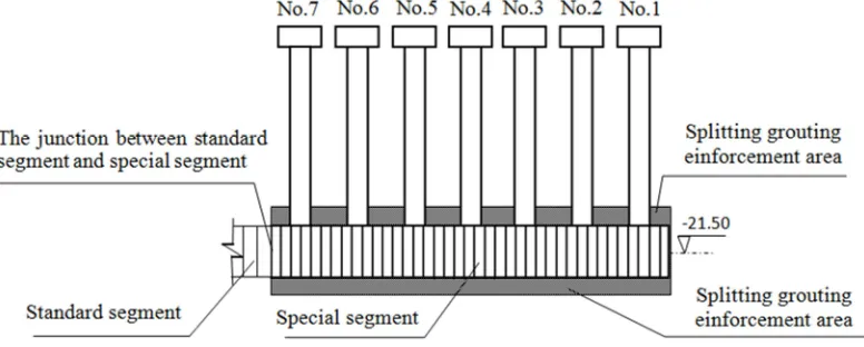
According to the design calculation and field test (specific design and complex check calculation is more complicated, and will be detailed in a separate article). Grouting through the grouting hole reserved on the shield segment [5] [6]. the mixture ratio of slurry is 1:0.5, the grouting pressure is 0.3-0.5MPa, and the grouting range is the special section of the shield. Within the range of 3m (as shown in Figure 4). When grouting, three items should be strictly controlled:
(1) Strictly control grouting pressure and avoid excessive or too small pressure. If the pressure is too small, it can not guarantee the effect of grouting reinforcement; if the pressure is too large, the bottom of the shield will rise, and the interface of the shield is open, causing leakage, even sand boiling and quicksand.
(2) The location of the intake should be vacated without grouting. Otherwise, the resistance will be increased significantly, resulting in failure of jacking up.
(3) When grouting, the opening and closing time of the grouting valve should be well controlled, so as to avoid pouring the external high-pressure water into the tunnel.
5.2.2. Reinforced Concrete Reinforced Belt at the Bottom Considering that the grouting reinforcement in the horizontal tunnel in the bottom of the river, the poor working conditions and the complex soil in the grouting range (the disturbance of the shield) may lead to the uneven grouting. Therefore, it is decided to place the 300mm thick reinforced concrete reinforced belt at the bottom of the tunnel, strengthen the integrity and stiffness of the tunnel, and ensure the safety of the jacking (as in Figure 5). When determining the thickness of the concrete reinforcement zone, the intake section should be checked because the water intake section is reduced.
Figure 5. Reinforced concrete reinforcing band at the bottom of the tunnel.
In the construction process, should pay special attention to the following three points:
(1) it is very difficult for steel and concrete to be transported to the head of special shield segment from the inlet of the circulating water pump room. Before pouring, it should be fully prepared to ensure the continuity of concrete pouring.
(2) Before the concrete is poured, the high strength bolts between the segments of the reinforcing strip should be tightened up.
(3) Strengthening sediment and accumulated water at the bottom should be cleaned up so as to avoid the separation of new reinforcement and special segments.
5.3. Construction Procedure and Key Points of Vertical Jacking
The vertical jacking equipment is arranged. As mentioned above, in order to reduce the effect of jacking on adjacent risers. The jack up sequence adopts the interval jacking scheme, that is: first, the construction of 1, 3, 5, 7 vertical pipes, and then 2, 4, 6 vertical pipes(s shown in Figure 4.)
5.3.1. Vertical Jacking Equipment Assembly and Adjustment After assembling the vertical jacking equipment, shift it to the first standpipe position, then adjust the counterforce levelness and fix it. The levelness control of the counterforce is very important. Otherwise, the vertical deviation is too large after the pipe jacking has a certain distance, and it may be stuck by the reserved hole.
5.3.2. Installed Water Stop Framed Around the Retaining Steel Door
The gap between the water stop frame and the special segment of the shield should be strictly controlled.
5.3.3. Stallation of Water Stop System
After the first section of the vertical pipe (top closed) is in position, the jack cylinder is raised to the appropriate height, the M24 bolt is used to connect the jack to the steel door, and the cement mortar will be used to block the connecting flange of the flange and the outer flange of the vertical pipe. At last, the sealing flange is installed, and the two flanges between the upper and lower parts of the water stop at about 4-5 40mm diameter, and the lower flange should be reliably connected with the bolts.
5.3.4. Dismantling the Bolts Around the Seal
After the second section of pipe are positioned and connected with the first section pipe, they continue to lift to the highest position, then remove the bolts around the head and begin to enter the jacking stage. Attention should be paid to the removal of bolts by the way of interval dismantling to balance the release stress.
5.3.5. Pipe Jack Up
At the beginning, the resistance is the biggest and the reaction force is the largest. The oil pressure should be increased step by step, and the perpendicularity of the vertical pipe should be strictly controlled. If it is found that the vertical pipe is torsional and the perpendicularity exceeds the standard, it should be adjusted in time [8]. When the pipe rises to a certain height, if the reaction force is too large, it should continue jacking in about 50mm, resting for 3-5 minutes, retracting the same height, and then jacking. At this point the resistance will generally decline. After the pipe section is lifted, the steel flange is used to support the lower flange of the vertical pipe, and the jack is retracted, and the next section of the pipe is installed.
5.3.6. End Pipe Fixation
5.4. Monitoring of Vertical Jacking
In order to accurately control the deformation of horizontal shield segments and prevent excessive deformation, the following monitoring is carried out in the construction: (1) the horizontal shield settlement (deformation) in the jacking section [9]; (2) the bolt stress between the segments; (3) the opening degree of the joint in the jacking section; (4) the opening between special segments and standard segments. To monitor the above item (4), it is mainly to take into account that the material and rigidity of the special segments and the standard segments are different. When the special segment is stressed, it is a weak link and it is necessary to strengthen the monitoring.
In view of the above monitoring contents, it is necessary to compile monitoring procedures to determine monitoring plans, monitoring equipment and alarm values. At the same time, according to the monitoring plan, a contingency plan should be worked out to formulate countermeasures for possible
problems in the process of jacking up. If the monitoring value approaches or exceeds the alarm value, the construction shall be suspended, and the corresponding measures shall be taken according to the requirements of the emergency plan before continuing construction.
6. Abnormal Situation and
Countermeasures in the Course of
Construction
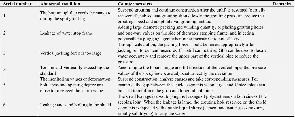
Because of the large risk and uncertainty [10] in the vertical jacking process of the water intake tunnel, a perfect contingency plan must be set up in the construction process, enough emergency supplies are equipped, and the training must be organized. The main abnormal situations that may be encountered during construction and the corresponding countermeasures are shown in Table 1.
Table 1. Possible abnormal situation and Countermeasures in construction process.
Serial number Abnormal condition Countermeasures Remarks
1 The bottom uplift exceeds the standard
during the split grouting
Suspend grouting and continue construction after the uplift is resumed (partially recovered); subsequent grouting should lower the grouting pressure, reduce the grouting speed and adopt interval grouting method
2 Leakage of water stop frame
Adding large diameter packing and winding quantity, or placing grouting holes and one-way valves on the side of the water stopping frame, and injecting polyurethane plugging agent when other measures are not effective
3 Vertical jacking force is too large
Through calculation, the jacking force should be raised appropriately after jacking reinforcement measures. If it still can not rise, GPS can be used to locate water accurately and remove the upper part of the vertical pipe to reduce the pressure
4 Torsion and Verticality exceeding the
standard
According to the torsion angle and tilt direction of the vertical pipe, the pressure values of the six cylinders are adjusted to rectify the deviation
5
The monitoring values of deformation, bolt stress and opening degree are close to or exceed the alarm value
Suspend construction, analyze causes and take corresponding measures. For example, the gap between the shield segments is too large, and U steel plate can be used to reinforce the girth and longitudinal joints
6 Leakage and sand boiling in the shield
The small leakage is used to plug the leakage of polyurethane on both sides of the seeping joint. When the leakage is large, the grouting hole reserved on the shield segments is injected with double liquid slurry (cement and water glass mixture, rapidly solidifying) to stop the water
7. Conclusion
After careful management and standardized construction, the diversion tunnel project has been successfully completed. The measured counterforce is slightly smaller than the calculated value during the jacking up, which shows that the selected calculation model is reasonable and accurate. But there are two abnormal conditions in the whole process. The fist is that the bottom segments is partially uplifted 20mm when grouting. The second is one of the vertical pipe vertical degree exceeding the standard when jacking, which causes the vertical pipe to be jammed and the resistance is greatly increased. The above two problems were dealt with in a timely manner in accordance with the measures of the contingency plan, which did not cause adverse effects on the project.
Compared with the general pipe jacking, the vertical jacking construction technology of the diversion tunnel has the characteristics of high risk and complex technology, and
the maturity of the technology is not high, and there are many links worth studying and improving. Because this kind of operation generally goes deep into the large water body several kilometers away, tens of meters deep soil layer, once the problem occurs, the consequence is unthinkable. Therefore, there is a lot of work to be done in terms of technical reliability and improvement of contingency plans.
References
[1] Zhou Peng, “Several common risks and Countermeasures in drainage and drainage works of coastal power plants,” Journal of Goods and Quality, China, pp: 113-114, June 2012. [2] Li Qianqian, Zhang Dingli, Fang Qian, Li Dong, “Study of
[3] Ding Zhi,“Prediction of Deformation and Study on the Influence of Shield Tunnel on Adjacent Buildings,” Doctoral thesis, June8. 2014.
[4] Mucahit Namli, Erol Guler,“Effect of Bentonite Slurry Pressure on Interface Friction of Pipe Jacking,” Journal of Pipeline Systems Engineering and Practice, Volume 8, Issue 2 Online publication date: August 22, 2016.
[5] Zhang Qingsong, Zhang Lianzhen, Liu Rentai, Yu Wensheng, “Split grouting the ory based on slurry-soil coupling effects,” Chinese Journal of Geotechnical Engineering, Vol. 38, No. 2, pp: 323-330, February 2016.
[6] Zhang Lianzheng, Li Zhipeng, Zhang Qingsong, Liu Rentai, Zhang Xiao, Yu Wensheng, “Split grouting mechanism base on nonlinear characteristcs of compression process soil,” Chinese Journal of Geotechnical Engineering, Vol. 35, No. 7, pp: 1483-1493, FeJuly 2016.
[7] Ye Junneng, Liu Yuan, Cheng Renpeng, Tang Lujun,“Study of
the Permissible Value of Upward Floating fou Segment in Shield Tunnel Construction,” Chinese Journal of Rock Mechanics And Engineering, Vol. 33, Supp. 2, pp: 4067-4074, Aug 2014.
[8] Dong Zelong, Xu Gang, Xu fei, “Construction method of underground butt joint in pipe jacking construction,” Journal of China Municipal Engineering, China, Vol. 48, No. 1, pp: 57-59, April 2008.
[9] Sun Changxin, Han Linxin, and Gao Feng, “Research on Stress Rotation and Plastic Deformation of in Tunnel during Excavation,” Journal of Modern Tunnelling Technology, China, Vol. 48, No. 1, pp: 6-11, February 2011.