S O F T W A R E
Open Access
Implementation of workflow engine technology
to deliver basic clinical decision support
functionality
Vojtech Huser
1,2*, Luke V Rasmussen
1, Ryan Oberg
1and Justin B Starren
3Abstract
Background:Workflow engine technology represents a new class of software with the ability to graphically model step-based knowledge. We present application of this novel technology to the domain of clinical decision support. Successful implementation of decision support within an electronic health record (EHR) remains an unsolved research challenge. Previous research efforts were mostly based on healthcare-specific representation standards and execution engines and did not reach wide adoption. We focus on two challenges in decision support systems: the ability to test decision logic on retrospective data prior prospective deployment and the challenge of user-friendly representation of clinical logic.
Results:We present our implementation of a workflow engine technology that addresses the two above-described challenges in delivering clinical decision support. Our system is based on a cross-industry standard of XML (extensible markup language) process definition language (XPDL). The core components of the system are a workflow editor for modeling clinical scenarios and a workflow engine for execution of those scenarios. We demonstrate, with an open-source and publicly available workflow suite, that clinical decision support logic can be executed on retrospective data. The same flowchart-based representation can also function in a prospective mode where the system can be integrated with an EHR system and respond to real-time clinical events. We limit the scope of our implementation to decision support content generation (which can be EHR system vendor
independent). We do not focus on supporting complex decision support content delivery mechanisms due to lack of standardization of EHR systems in this area. We present results of our evaluation of the flowchart-based
graphical notation as well as architectural evaluation of our implementation using an established evaluation framework for clinical decision support architecture.
Conclusions:We describe an implementation of a free workflow technology software suite (available at http:// code.google.com/p/healthflow) and its application in the domain of clinical decision support. Our implementation seamlessly supports clinical logic testing on retrospective data and offers a user-friendly knowledge representation paradigm. With the presented software implementation, we demonstrate that workflow engine technology can provide a decision support platform which evaluates well against an established clinical decision support architecture evaluation framework. Due to cross-industry usage of workflow engine technology, we can expect significant future functionality enhancements that will further improve the technology’s capacity to serve as a clinical decision support platform.
* Correspondence: [email protected] 1
Biomedical Informatics Research Center, Marshfield Clinic, Marshfield, WI, USA
Full list of author information is available at the end of the article
Background
Currently, there is a strong interest in improving deci-sion support systems (DSS) [1]. Despite several decades of effort, we have been unable to develop DSS platforms that would gain wide adoption [2]. Some solutions are embedded in a proprietary system or are tied to a parti-cular electronic health record (EHR) vendor which lim-its their adoption. Other solutions often introduce a healthcare-specific representation format and health-care-specific execution engines, whereas past experience shows that successful healthcare solutions often rely on cross-industry standards. Finally, easy authoring or easy review of DSS logic still remains a considerable chal-lenge [3]. We present our implementation of a workflow engine technology [4] which addresses two current chal-lenges of DSSs.
The first challenge is the ability to evaluate DSS mod-ules prior to deployment. For seamless testing and deployment, it is beneficial to be able to easily switch the execution of a DSS module from prospective to ret-rospective mode. Traditionally, this problem has been solved by two approaches, both of them sub-optimal and requiring additional resources. The first approach involves deployment of the module at a pilot site prior to enterprise-wide deployment and fine tuning the logic directly within the deployment environment. The sec-ond approach is a separate side-project for each deployed module which extensively analyses the possible impact of the intended DSS module. This separate side-testing usually involves a separate DSS logic representa-tion for such retrospective testing (compared to the deployment prospective version of the logic).
The second challenge is the ability of non-program-ming clinicians (as recipients, reviewers, maintainers, or authors of decision support) to understand and manipu-late the logic of a given DSS module. From a perspective of non-programmers, it can also be described as a
“black-box phenomenon.”A clinician who cannot review in detail the logic of a given decision support system may be reluctant to adopt a system that he can not fully understand.
We were able to address the two above-mentioned challenges with a system calledHealthFlow, which is an implementation of a workflow engine in the context of an EHR system. This software category article aims to provide implementation details for informaticians and champion clinicians at healthcare organizations that may be considering workflow engine technology to enhance their decision support functionality. We use the term
clinical logic to encompass not only decision support
problems, but also knowledge representation for domains of quality improvement and clinical research alerts [5]. The HealthFlow project is an effort to utilize a workflow editor and a cross-industry process definition standard to
represent clinical logic and to use a workflow engine to execute such logic. Key objectives of the HealthFlow pro-ject are: (1) the ability to switch seamlessly from retro-spective execution mode for prior-deployment testing to prospective mode; (2) the ability of non-programmers to review the executable logic in a user-friendly fashion (graphical, step-based flowcharts); and (3) the interoper-ability of the encoded executable logic across different healthcare institutions. The HealthFlow system described in this article consists of two components that share a set of common characteristics. We use the termRetroGuide
for the retrospective mode of operation, and our initial work with workflow technology focused on modeling ret-rospective and analytical processes is presented elsewhere [6] (a comprehensive set of our desired functional requirements for a healthcare process modeling platform is published separately [7]). For the prospective compo-nent of the system, we use the termFlowGuide, and it was developed later as a distinct component within the HealthFlow project. The functional specification for the prospective component did not stem from a fixed set of initial requirements, but instead were an effort to maxi-mize the use of functionality already included in a work-flow technology suite.
Several prior studies report the use of workflow tech-nology (WT) in healthcare, and we briefly survey some of these studies. Emanuele [8] presents the use of WT to improve infection control and proposed a term
work-flow-enabled EHR system, which can communicate
languages. A later subsection of this article (architectural evaluation) further compares and analyzes workflow technology-based approach to decision support in com-parison to other decision support platform using an architectural evaluation model [15]. In the following sec-tion, we present the architecture overview of our WT implementation, typical usage phases, how the system interfaces with available clinical data and healthcare environment, and a use case example.
Implementation
Overview of the architecture
HealthFlow system is an implementation of a workflow management system (WfMS) [4]. Such a system offers the ability to model a process as a graphical flowchart in a workflow editor and execute such process in a work-flow engine. A workwork-flow process would contain steps involved in a given decision support problem (e.g., hypertension screening logic). We prefer to use the term
scenario as a clinician-friendly synonym to a workflow
process in order to better communicate the clinical con-text of a given workflow process definition.
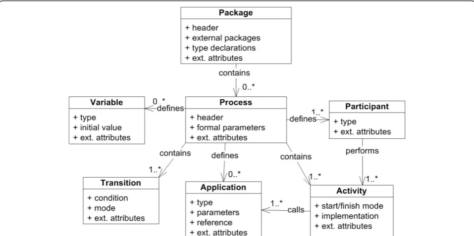
We currently use Together Workflow Editor http:// sourceforge.net/projects/jawe as our main editor for viewing and creating executable scenarios. HealthFlow utilizes a standard XML Process Definition Language (XPDL) which is a standard defined and maintained by Workflow Management Coalition (WfMC; http://www. wfmc.org/xpdl.html). Adherence to this standard avoids vendor lock-in problems (ability to switch to workflow suite from a different vendor). It also enables inter-institutional sharing of the modeled scenarios. Figure 1 shows a high-level class diagram of the XPDL standard with the root element of a workflow package containing individual process definitions. Key compo-nents of each process definition are applications, parti-cipants, activities, transitions, and variables [16]. Additional diagrams of the XPDL schema are pre-sented in [Additional file 1].
For scenario execution, we use Together Workflow Engine http://sourceforge.net/projects/sharkwf. Our existing implementation structurally relies on an open source workflow suite; however, it can also be imple-mented on more feature-rich, commercial, XPDL-com-pliant workflow suites (e.g., Tibco business process management platform from Tibco software (Palo Alto, CA, USA) or Fujitsu Interstage platform). We chose the XPDL standard over other workflow definition lan-guages (e.g., Business Process Execution language (BPEL), [17]) or Business Process Modeling Notation (BPMN), [18]) because it has the widest adoption among the workflow system vendors [19]. Another advantage of the XPDL standard (in contrast to BPEL) was its ability to provide a corresponding graphical
flowchart-like version of a processes definition in addi-tion to a code-like version.
To provide an interface to clinical data and the EHR system as well as some other custom functionality, HealthFlow extends the workflow engine and editor with a set of small and modular external applications
(EAs). The majority of the logic of the clinical scenarios and the key strengths of our implementation lie in using XPDL graphical flowchart constructs. External applica-tions are used only when XPDL constructs are insuffi-cient or for interfacing with other systems. In our current implementation, these lightweight and modular external applications are developed in Java, but other modalities are possible with most workflow management systems, such as a web service, a JavaScript script, or executables programmed in other programming lan-guages. Also, these applications currently operate on a native HealthFlow event model, but it is possible to cre-ate versions of those applications that opercre-ate on other event models; for example event models and data struc-tures of a vendor based EHR system, openMRS (Open Medical Records System, [20]), or HL7’s vMR model (Virtual Medical Record [21]). For a detailed description and purpose of an event model, we refer the reader to Huff et al.’s work [22]. In pilot experiments, we have successfully demonstrated HealthFlow’s ability to oper-ate on an event model of version 1.3 of i2b2 (as repre-sented in the i2b2 OBSERVATION_FACT table schema). i2b2 [23,24] stands for Informatics for Inte-grating Biology and the Bedside and it is an emerging platform for storing and querying EHR data, developed at Partners HealthCare with a grant from the National Institute of Health, USA. This proves that HealthFlow capabilities can be easily adopted by sites that converted and imported their data into an i2b2 repository. We use HealthFlow event model because it offers a more elabo-rate event structure than i2b2 native model (version 1.3 of i2b2). In HealthFlow event model certain common event characteristics are represented as native event data components (e.g., event type and event subtype), instead of using i2b2’s event attributes structure. We further comment on the relationship of HealthFlow and i2b2 in the discussion section.
content to a care coordinator role rather than scenarios with fully-developed and sophisticated alert delivery and usability logic). Ability to integrate into the EHR depends on the decision support platform but also on the host EHR. Peleg [10] defines this as a third level of decision support integration, and Emanuele and Koetter [8] use the term“workflow-engine enabled” EHR system when the EHR can communicate with a workflow engine by sending pertinent healthcare event data to the engine and conversely receive tasks generated by the engine.
Multiple complexity levels
Various decision support solutions (e.g., Arden Syntax [25], GLIF (Guideline Interchange Format, [3]), EON [26], ProForma [27]) have addressed with various degrees of success many challenges in DSS [10]. We would like to discuss two factors that we consider important: (1) a given DSS platform can support multi-ple levels of commulti-plexity on a commulti-plexity-functionality curve; and (2) a DSS platform provides a flexible inter-face to the outside-world. A common theme in DSS, since the days of Arden Syntax’s curly braces problem [28], is the fact that a DSS platform must interface with external systems (e.g., EHR system or/and Clinical Data Repository). Dealing with external complexity may in fact require significantly more expertise then construct-ing the clinical logic itself. To achieve balance between complexity and functionality, we have designed the HealthFlow system to have three different levels of
external complexity (basic, advanced, and ultimate). We refer to these three levels as HealthFlow usage levels
because they entail multiple aspects. For example, a sim-ple decision support problem can be fully captured on a basic usage level (e.g., obtain one most recent laboratory result for a single test, compare it to a critical threshold, and alert); whereas, a more complex logic operating with multiple parameters that may interact with each other, may require advanced or ultimate HealthFlow usage level. The first aspect of the usage level is the complexity and configurability of the external applica-tions employed by the scenario flowchart. The second usage level aspect is the overall look of the scenario flowchart (e.g., basic usage level flowcharts [or flowchart steps] are easier to understand for non-programmers than flowcharts at the advanced or ultimate usage level). We discuss the three usage levels in greater detail in a later sub-section describing the external applications.
Three HealthFlow usage phases
The use of HealthFlow can be divided into three phases; (1) scenario creation, (2) scenario testing (RetroGuide), and (3) scenario deployment (FlowGuide). In most cases, phases 1 and 2 are repeated iteratively until the resulting scenario and HealthFlow-generated reports fully address the knowledge representation problem at hand. Depending on the nature of the project, the phase 2 scenario testing version may be deployed as a prospec-tive module with no or small modifications. This ability directly addresses the first challenge we described in the
introduction (ability to test clinical logic on retrospec-tive data). In order to understand the relationship of the retrospective and prospective mode of HealthFlow operation, we must first explain the concept of a current temporal position in the EHR record. In retrospective
mode (RetroGuide)the scenario consumes all available
EHR events; it does not wait for an event to happen, but instead searches for it beyond the current temporal position. A data warehouse (or other comparable clinical data repository entity) is a primary component used in this mode, as it provides an optimized platform for searching through all historical clinical data. A given step in the scenario flowchart simply retrieves retrospec-tive EHR data. For example, the step may contain logic to “find date of the next outpatient visit to pediatrics after discharge from hospital”. In prospective mode
(FlowGuide), however, the “future-oriented” scenario
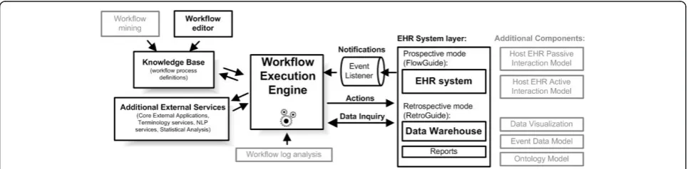
flowchart steps are switched to wait for a particular event to arrive via event listener. In this mode, the engine communicates directly with the EHR system in real-time. To illustrate this on the previous example of pediatric visit, the workflow engine would maintain a status of a scenario instance, which would be in paused mode, until a pediatric visit would happen. Figure 2 shows the overview of the architecture and depicts the two modes of operation. It shows that the FlowGuide component primarily interacts with an EHR system and point-of-care, whereas the RetroGuide component works with a data warehouse layer, and scenario conclu-sions (proposed prospective actions) are merely docu-mented in a retrospective execution report and not sent to the point-of-care. Figure 2 also shows additional components of the architecture, such as the knowledge base consisting of process definitions (scenarios) and workflow editor. The set of HealthFlow modular exter-nal applications (EAs) is included in the additioexter-nal external services box. The figure also includes (in gray) additional architectural components such as the event model and the ability to analyze workflow logs or obtain
scenario definitions using workflow process mining techniques [29].
Before describing the individual phases, we need to more precisely define a HealthFlow scenario. Ascenario, which is in workflow technology terms a fully executable workflow process definition, consists of two key layers: a graphical flowchart layer and a hidden code layer. The
flowchart layercan be created and reviewed by users with limited programming expertise (e.g., champion clinicians or other non-expert requestors of a clinical logic module such as administrative and management level healthcare personnel or researchers). Thecode layeris hidden behind the nodes and arrows of the flowchart and contains refer-ences to modular applications that can (1) obtain EHR data (or listen/wait for them), (2) provide various analytical functions using any external technology, or (3) perform an action within an EHR system at the point-of-care (or document such action within a report when in retrospec-tive mode). This hidden code essentially utilizes Health-Flow EAs, or it can call any external computer application or a web service. Finally, a HealthFlow scenario has yet an additionalvariable layerwhere relevant information can be passed between flowchart steps (e.g, average systolic blood pressure at age 60-65). We will describe each of the three HealthFlow phases in detail.
First phase: Scenario Development
The first phase of scenario development involves the creation of a sequence of steps, relying on HealthFlow’s external applications. Each step is modeled as a node in a flowchart. Each node may contain the execution of one or more EAs. Arcs connecting the nodes represent the flow of logic. See figure 3 for an example scenario. Six additional scenario examples can also be found in [Additional file 2]. The graphical nature of a HealthFlow scenario facilitates collaboration between a (1) requestor
(usually a clinician, but it can also be a researcher, administrator, or other domain expert) who develops the scenario using the graphical flowchart and the tex-tual description fields that specify what each node or arc
should perform, and the (2) collaborating knowledge
engineer, knowledgeable about EAs, who makes the
sce-nario executable by filling in the necessary computer-interpretable components.
Second phase: Scenario Testing (RetroGuide)
During the second scenario testing (RetroGuide) phase, the model is executed by the workflow engine using
retrospective data from a set of patients (testing cohort). The scenario testing phase can be divided into two major steps: actual execution, and a reports review step. During the executionstep, the workflow engine uses a single patient modeling and execution approach, where the scenario is run for each patient as an individual. Several reports are built during the execution step, cap-turing the execution trace of the scenario for each exe-cuted patient from the testing cohort. In addition to a single patient execution trace, data views are also pro-vided to enable population view of the execution. Optional custom reports can also be built, documenting patients that satisfied certain combinations of steps or conditions (conclusion steps). The execution by default proceeds forward in time, and the concept ofcurrent positionin the chart is important. The process is analo-gous to a human research abstractor performing manual chart review. The process is best understood by envi-sioning a robot that is browsing a chronologically ordered series of coded clinical events found in an EHR. The robot (RetroGuide) hypothetically starts at the first EHR event and advances through the record according to the flowchart step-wise instructions.
The second step ofreports review involves the analysis of how well the HealthFlow scenario addresses the clini-cal problem or logic at hand. This is achieved by using HealthFlow data visualization components (see figure 2). Three main data views are available: summary report, detailed report, and individual patient view. HealthFlow
summary report lists cohort-based statistical results, e.g.,
“How many cohort patients satisfied a particular sce-nario step, branch or condition?” The second,detailed report is patient-centered and offers additional details about scenario execution, e.g., exact values, timestamps and codes for individual EHR events investigated by the scenario. Finally, the third report offered by HealthFlow,
the individual patient view(IPV), lists all EHR events
for a particular patient. The review of selected patients within the detailed report and individual patient view is the basis for iterative improvements to the scenario logic. Several examples of scenario flowcharts and reports can be found on the HealthFlow project website http://healthcareworkflow.wordpress.com.
During retrospective testing, several aspects of the sce-nario are evaluated which are mainly oriented towards whether a meaningful decision support content is gener-ated out of a proposed scenario logic:
(1)What percentage of the initial testing cohort has an action/intervention alert generated?
This evaluation aspect is based on the assumption that a given new scenario checks certain clinical aspects of a patient which results in no action or intervention in compliant patients or some new
action in non-compliant patients. In the first compli-ant case, the clinician’s work is not changed and no interruptions occur. In the second non-compliant case, the clinician’s work may be affected by one or several types of new actions. For example, new rele-vant information is being passively displayed, or the user is interrupted with a new data entry or choice selection dialog. In other words, if the scenario logic checks a quality improvement initiative and the non-compliant percentage of patients is too high (e.g., more then 50%), the new decision support content could be too aggressive, and other means of inter-vening may be chosen (e.g., quarterly educational intervention supported by peer-comparison and ret-rospective data review, rather then too frequent, point-of-care decision support). Similarly, if the number of affected patients is too low (e.g., less then 3%), it may not be cost effective to justify creation and costly enterprise maintenance of a new decision support content for this problem. However, this also depends on the severity of the clinical consequences in a non-compliant patient. Iterative review and changes to the trigger criteria, clinical logic thresh-olds, or number and types of possible output actions during this second RetroGuide phase can result in achieving an optimum balance between the pro-jected impact of the new decision support module on clinicians, necessary information campaign about the new module, and significance of the new mod-ule’s clinical domain.
(2)Does the scenario logic perform similarly on addi-tional testing cohorts (e.g., other geographic regions, different physician groups)?
The initial testing is usually done in a cohort sug-gested by the scenario requestor(s) (e.g., patients from a given clinic with certain trigger criteria). After basic scenario logic fine tuning, an integral part of the retrospective testing phase is execution on cohorts from other clinics or on an enterprise-wide cohort, to see whether the same logic can be deployed enterprise-wide, or whether the new logic will require more complex local customizations (e.g., same logic applied only in selected sub-populations [physician groups, regions, or patient groups]) or several versions of the logic with slight modifications for different contexts. In some implemented scenar-ios, retrospective testing in additional cohorts signifi-cantly influences the final logic, and the scenario authors are surprised with results of this testing and variability and number of possible data patterns in different populations. In such cases, there could be tens of iterations between scenario modifications and testing.
(3) Do additional exclusion criteria need to be
added, based on review of patients affected by the new logic?
For example, during retrospective testing of the newly proposed very high cholesterol patient sce-nario (patients with recent low-density lipoprotein [LDL] lab result of 190 mg/dL or more), we addi-tionally excluded patients coming for oncology and/ or optometry appointments based on the requestors clinical consensus. It is important to also note, that while review of retrospective results provides useful inputs, it may not cover all possible situations depending on the size of the retrospective cohort. It complements, but not eliminates, evaluation of the later prospective scenario deployment.
The functionality of the retrospective RetroGuide component of our workflow engine implementation can also be used as a standalone tool for flowchart-driven data analysis and is closely related to many cohort size estimation query tools [6]. However, the ability to use the same flowchart representation paradigm for retro-spective as well as proretro-spective execution mode distin-guishes our implementation from many other research efforts. Additional examples and descriptions of the sec-ond RetroGuide phase can be found in published case studies on Hodgkin’s lymphoma [30], hypertension [31], inpatient glucose control protocol [32], hepatitis C treat-ment and adverse drug events after use of narcotics [33], and osteoporosis and cholesterol control [34].
Third phase: Scenario Deployment (FlowGuide)
The third phase of scenario deployment (FlowGuide) uses the same framework as the retrospective Retro-Guide phase, with a few exceptions. FlowRetro-Guide prospec-tive scenario may be created from scratch (very uncommon) or can be based on a retrospective Retro-Guide scenario (most frequent). We will focus our description on the second case and also explain what changes occur when a retrospective scenario is made to run prospectively. A FlowGuide scenario consists of five types of possible flowchart steps: trigger, background, analytical, listen, and action nodes. Two of the types, background and analytical nodes, are also present in ret-rospective RetroGuide scenarios.Trigger steps start the scenario. For example, a visit to rheumatology is sched-uled for today or a surgical report is filed: there can be one or multiple trigger steps.Backgroundsteps find past events in the EHR (at runtime). For example, find ear-liest instance of rheumatoid arthritis diagnosis or find latest pharmacy record (prescription, renewal, or discon-tinuation) for a biologic agent such as infliximab.
Analy-tical steps manipulate data obtained via previous
blood pressure value, determine follow-up frequency cri-terion (every year or every two years).Listen steps wait for a given EHR event to occur in real time. For exam-ple, wait for a discharge event in a patient previously triggered by a surgical report creation. Listen steps share the same event data model with background steps. During retrospective-to-prospective scenario translation, listen steps are created from background steps by chan-ging the mode from retrospective search scope (search for a specific past EHR event in a given patient) to wait-ing, prospective scope (wait until a specific event occurs to a given patient). Finally, action stepsperform actions within a given EHR system (or other related system, e.g., Clinical Trial Management System). Actions may involve updating a report or registry, sending an email, generat-ing an alert, creation of an order, or order cancellation. Full range of previously identified intervention types (notify, log, provide defaults, show guidelines, etc.) is supported with proper interface support of the interven-tion target system [35,36]. During retrospective-to-pro-spective scenario translation, action steps are often created from conclusion steps by changing the action from‘retrospective report conclusion creation’to a par-ticular prospective action. Although we emphasize the ability to test a given clinical logic retrospectively, it is important to note that not all possible prospective sce-narios can be tested retrospectively. Prospective scenar-ios that contain manual human steps (e.g., prompt clinician for symptom severity) cannot be tested retro-spectively because the new proretro-spectively collected data are not present in the retrospective dataset used in Ret-roGuide mode. Limited testing may be performed if the scenario can be decomposed into smaller sub-scenarios which are fully functional on retrospective data.
HealthFlow External applications
We designed the HealthFlow system with several usage groups in mind. Our primary goal was to support the ability of a non-expert scenario requestor to passively understand the scenario logic and be able to review the logic. This also includes the ability to review any itera-tive changes to a scenario as it is being collaboraitera-tively authored by the requestor and the collaborating knowl-edge engineer. Thescenario-reviewerrole is mostly sup-ported by the graphical nature of the scenario and the ability to use hierarchical arrangement of scenarios (i.e., a node may expand into multiple steps by using sub-flows). The secondary design goal was to also empower a non-expert requestor to even be the scenario-author, or to support very close requestor-knowledge engineer collaboration. To support a whole range of simple and complex functionality, we adopted an approach of sev-eral distinct HealthFlow usage levels (or complexity levels). This approach was inspired by historical
development of the HealthFlow system, where we kept adding new, more complex, functionalities while also retaining their simpler versions for basic problems. Within this approach, we define three usage levels with increasing complexity: simple, advanced, and ultimate. A higher level can always utilize strategies and applications from all lower usage levels, and a given scenario may combine nodes (scenario steps) authored at different levels. During the last six years of developing the HealthFlow system, each usage level was populated with an initial set of external applications. However, each level can evolve and have additional capabilities added. The division into exactly three usage levels and func-tionality boundaries of each usage level are based on our analysis of existing HealthFlow scenarios, our inter-actions with scenario reviewers and authors, and system buy-in and training considerations (e.g., short training time and a favorable learning curve for simple problems, and non-expert users with the potential for more com-plex training and system use later).
The simple level uses EAs with a small number of
parameters (zero, one, or two input parameters and one output parameter) which are easier to understand. A basic example of a simple EA is a lookup for patient gender using a step in a flowchart that contains an EA call of ‘Patient_is_male()’and returns true if the patient is male, false if female, and null if gender information is not in the EHR. In a simple level, a separate EA is defined for each event type (total of 9 EAs, e.g., Diagnosis(ICDDxCode), FindLabResult(LabCode), Find-Visit(AppointmentTypeCode)). Only a single event can be the result of a simple ‘find event’ instruction, and only a simple found/not found boolean output is avail-able for scenario branching logic. All simple level EAs operate in a “strict pointer mode”which means that the hypothetical robot moves the current position pointer to the EHR position where its last step succeeded, or stays at the previous position if it failed. For example, a step using FindLabResult(LDL-cholesterol_code) after estab-lishing the onset of lipid-lowering pharmacotherapy will return true if such follow-up test is found, and the cur-rent position pointer will move to a new EHR position. This behavior is similar to browsing and searching for events in a book; however, the pointer position can be manipulated by using“jumping”operations (e.g., Jump-ToLastEHREvent or JumpForwardXMonths).
variables). For example, FindCodedEvent with time boundaries of chronic kidney disease onset date to regu-lar dialysis onset date: the outputs of advanced EAs are also extended and include all event properties such as event numeric value, coded value, or flag. Find event operation can return not just a single event, but also a set of multiple events, and the scenario can perform simple operations with these sets (e.g., use the count of events in the result set in branching logic such as if more than 3 dialysis events are found in the last 12 months since current or other arbitrary position). There is a total of 7 advanced EAs also with new types of applications added, such as EAs related to variables (AssignValueToVariable, IncreaseCounterVariable) and temporal EAs (EvaluateTwoTime-stampsDifferenceCri-terion). Because of these additional capabilities, advanced level scenarios can be more complex to review for the requestor. The advanced usage level also offers the ability to export data generated within HealthFlow (using the HF-Export tool and CSV format) into exter-nal software packages (e.g., SAS or R). The export capa-city is performed after scenario execution and could technically be part of any usage level, but is included in advanced level mainly for training purposes.
Thirdly, the ultimate levelbuilds again on the pre-vious levels and offers the ability to analyze averages and sums of numerical parameters of sets of events (e. g., average systolic blood pressure in a result set of a find operation). The ultimate version of the FindCode-dEvent EA also supports the ability to use value sets derived from HealthFlow ontology and use terminology abstraction functionality. This enables it to use all chil-dren concepts (or only first degree chilchil-dren) with a par-ticular relationship to a given term (most often the‘is_a’ relationship). An example would be providing a concept code of a drug class (e.g., incretin mimetics) and let the HealthFlow ontology provide the enumeration of all cur-rent dispensable drugs in this drug class (e.g., exenatide, liraglutide, and taspoglutide). The ultimate level contains extended versions of some prior EAs and adds 4 new EAs and other model infrastructure dealing with retro-spective to proretro-spective transition (e.g., TriggerEventLis-tener, RelevantEventListener). From a modeling perspective, the ultimate level also introduces the use of looping logic in a flowchart which may be required for some complex problems (e.g., determining onset of chronic kidney disease using laboratory criteria). Addi-tional examples of EAs and their use can be found in previously published reports [33,37].
Finally, it is important to note that the HealthFlow sys-tem can be further extended to achieve functionality which is not covered by the external applications included in the three levels above. This is done by programming new,
pro-blem-specific external applications. Such new EAs may
provide‘de novo’functionality such as: (1) access a legacy system or data stored within a different data representation model; (2) call an external web service; or (3) provide inter-face to advanced analytical features (e.g., call an external reasoning engine such as Neural Network, Fuzzy Logic, Hidden Markov Model framework, or other paradigm that may provide superior capabilities in some domain [e.g., dealing with reasoning under uncertainty]). Creation of such problem-specific EAs involves custom programming and requires collaboration with a programmer.
An example use case
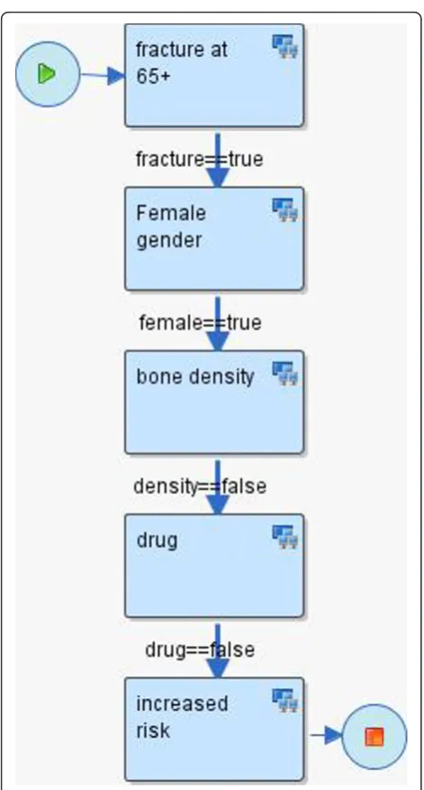
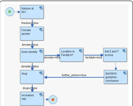
To illustrate HealthFlow use, it is perhaps best to opera-tionalize it. Consider the following clinical scenario in osteoporosis care in women over the age of 67. Dr. Jones, a family medicine physician and a medical home initiative advocate, attends a conference where a case of a woman with repeated fractures after age 67 is described and recommended management options are emphasized (bone density testing and preventive admin-istration of osteoporosis drugs). Upon returning from the conference, Dr. Jones wants to write a DSS module that would facilitate optimal care including the confer-ence recommendations. He drafts an initial flowchart of this problem using a workflow process modeling tool. This tool enables Dr. Jones to model a sequence of ana-lytical steps over EHR data and is easy to understand because it resembles a manual chart review. See figure 3 for the resulting initial flowchart.
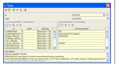
Mr. Clark, a collaborating knowledge engineer, receives the process flowchart in an email (XPDL file) from Dr. Jones and extends the nodes of the process flowchart with elements that enable execution of the flowchart. Figure 4 shows an example of a dialog box
within Together Workflow Editor that specifies execu-tion and parameters for an EA.
To facilitate communication and consistency, the knowledge engineer preserves the structure of the flow-chart (number of nodes, branches, and overall layout of the flowchart). The knowledge engineer then executes this extended process definition on a set of patients (e.g., 4000 females with a fracture) and emails back to Dr. Jones hyperlinks to web-based scenario retrospective execution reports (HealthFlow summary, detailed and IPV reports). Dr. Jones reviews the web-based reports and, based on a more detailed review of eight carefully selected patients, he identifies additional codes for bone density scores observed in the EHR of some of the patients. He decides to add a new process branch for a flagship family medicine center that is also collecting bone density Z and T scores in a structured EHR data entry form filled by medical assistants, which allows more specific decision logic within this branch. See figure 5 for the extended scenario. Several iterations of other process definition improvements occur, and Dr. Jones eventually concludes that the results of the retrospective fine-tuning of the process logic indicate that a meaning-ful and highly specific IT-intervention in a subset of osteoporosis patients is well justified. Dr. Jones uses the underlying process flowchart to share the analysis with his fellow physicians in the family practice clinic, who agree to a pilot deployment within their clinic. Dr. Jones sends the final executable scenario to the clinical decision support (CDS) team. The CDS team runs a
transformation script against the process definition file which replaces all data retrieval process steps (which run against the data warehouse) with corresponding data retrieval calls that run against the production clinical data repository (CDR). The transformation script also changes the alerting/recommendation target from a ret-rospective execution report to a recommendation section within a patient dashboard screen in the EHR system. Since the logic prototyping was patient based (rather than population based), no other transformation for switching retrospective to prospective functionality is needed. During the pilot, colleagues of Dr. Jones can see new types of recommendations being generated, and they can click on the small view-logic-link next to the new recommendation. This view displays the same flowchart they were presented at their meeting with the highlighted route through the logic for a particular patient in ques-tion. The view offers them the ability to provide feedback linked to a specific node of the flowchart or to the flow-chart as a whole.
Other components of the HealthFlow system
Event Model
The event model used by the HealthFlow system is based on decomposition of EHR data into events described by Huff et al [22]. There are two event models supported: basic and extended. The three levels of EAs included in HealthFlow (simple, advanced, and ultimate) utilize the basic model. The extended model can accom-modate any event structure, and in order to utilize it, custom EAs at the extended level have to be pro-grammed. For example, we have piloted the use of the i2b2 event model.
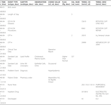
We further describe only the basic model. At the begin-ning of our workflow engine implementation project, our requirement was to create a simple event model that can cover 80% of the possible use cases, rather than an elabo-rate and comprehensive model. For example, the basic event model does not support the ability to recursively add additional event attributes outside of the provided basic set of event properties defined. The structure of the basic model has the following key event characteristics: patient_id, event date and timestamp, event type, event subtype, observation and coded value, value numeric, and value text. Additional characteristics are flag code, termi-nology2 code, and sequence_id. Each coded field has a corresponding code column and textual description col-umn. An example of several observations (using only description fields) is provided in table 1. Figure 6 shows the event structure in an entity relationship diagram together with the ontology structure.
Ontology
Our workflow engine implementation, similar to other clinical informatics systems, needs a standard way of
representing coded clinical concepts. Chosen representa-tion approach has a high impact on semantic interoper-ability of individual scenario steps, and to ensure that we strive to utilize, as much as possible, existing and widely-spread terminologies. HealthFlow uses an inter-nal native ontology that can accommodate standard established terminologies such as International Classifi-cation of Diseases (ICD) or Logical Observation Identi-fiers Names and Codes (LOINC), as well as local, proprietary ontologies. It supports any relationships among two concepts; however, the most important
relationship is an “is_a” relationship. The HealthFlow ontology model also allows a concept to have multiple parents via the same or different relationship. For exam-ple, the ICD-9 code for ‘prolonged depressive reaction’ can have one parent of psychiatric disorder and also be part of the depression Healthcare Effectiveness and Data Information Set (HEDIS) value set. Another example would be the concept atenolol can have an‘is_a’ rela-tionship to a beta blocker concept and a ‘has_indication’ relationship to the hypertension concept. This enables the ontology to support the search for drugs that are
Table 1 Event schema example
EV_TIME (ev_time)
EVENT TYPE (evtype_desc)
SUBTYPE (evsbtype_desc)
OBSERVATION (obs_desc)
CODED VALUE (cd_val_desc)
FLAG (flg_desc)
VAL_NUM (val_num)
TERM2_CD (term2_cd)
TERM2_DESC (term2_desc)
1990-01-01 00:00:00.0
Birth event
2046-04-23 00:00:00.0
Length of Stay 3
2046-04-23 00:00:00.0
ICD-9-CM Diseases
72610 ROTATOR CUFF
SYND NOS
2046-04-23 00:00:00.0
ICD-9-CM Procedures
8363 ROTATOR CUFF
REPAIR
2046-04-23 00:00:00.0
CPT-4 2 J3010 Inj, fentanyl citrate
2046-04-23 00:00:00.0
CPT-4 29999 ARTHROSCOPY OF
JOINT
2046-04-23 15:01:00.0
Clinical Text Data
Operative Report
2046-04-23 15:23:00.0
Standard Lab Data
Lipid Profile Cholesterol, Plasma Quant.
Higher Than Normal
327
2046-04-23 15:21:00.0
Standard Lab Data
Urine Mi-croscopics
Epithelial Cells, Urine
Occasional
2046-05-11 13:21:50.0
Problem Event Diagnosis Hyperlipidemia
2046-08-12 11:12:13.0
Patient Order Pharmacy order Meperidine Hcl, 50 Mg/Ml, Ampul
2047-01-18 10:55:01.0
Nurse Note 203.1.10.3.1.10.1.0 PURPOSEFUL
MOVEMENT
2047-01-18 15:23:30.0
Inpatient Drug 3513816 ELECTROLYTES
(NUTRILYTE) 42.9 ML, VIAL
2047-01-19 11:02:02.0
Discharged 43 ICU
indicated for a given disease (e.g., hypertension) as well as by drug class (e.g., beta blocker).
In our current implementation, we have ICD-9-CM and Current Procedural Terminology (CPT) standard terminologies loaded. Included proprietary terminologies are local lab codes, local diagnostic codes, and local codes for medical specialties and vendor-supplied drug terminology. Additional relationships included for user convenience are HEDIS tables covering ICD-9 diagnostic value sets. Ontology relationships can be used only when ultimate EA sets are used. Our experience with reques-tors indicates that many of them are not interested in uti-lizing complex terminology structures and prefer directly enumerating concepts of interests for a given scenario step. Figure 7 shows the HealthFlow ontology web-based browser displaying first degree children of the is_member relationship of the HEDIS concept of AMM-A value set (Antidepressant Medication Management, table A: diag-nostic codes to identify major depression).
Results
Current implementation at Marshfield Clinic
The workflow engine and the additional components of the HealthFlow system have been fully implemented at Marshfield Clinic (MC), and the system works in real time. We have created the necessary event listener (see figure 2) for MC’s EHR (CattailsMD™). Both major components (RetroGuide as well as FlowGuide) are operational.
Under an approved RetroGuide Institutional Review Board (IRB) protocol, 40+ different scenarios were
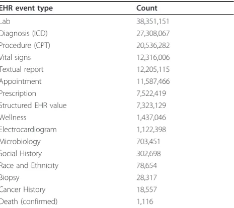
modeled by several analysts (see [Additional file 2] for examples) resulting in more than 360 execution reports being available in the RetroGuide project table. A Retro-Guide scenario is usually tested on a cohort of 500 to 5,000 patients which is drawn from a larger sample of 75,000 patients. This larger de-identified cohort contains a total of 145 million coded EHR events. Table 2 shows an overview of selected event types such as diagnoses, procedures, laboratory results, and other structured EHR data. To demonstrate the ability to share decision sup-port logic at a flowchart level, we have uploaded example scenarios to a decision support community wiki http:// www.clinfowiki.org/wiki/index.php/HealthFlow.
Figure 6HealthFlow event and ontology schema. HealthFlow data model schema showing the event table linked to the ontology table. For events table examples, see table 2.
Figure 7Ontology browser. Example showing HealthFlow internal ontology structure. This web-based applications allows the user to navigate concept children (HEDIS value set for depression diagnostic codes is shown). CCD abbreviation denotes a concept code.
Table 2 Coded EHR events statistics
EHR event type Count
Lab 38,351,151
Diagnosis (ICD) 27,308,067
Procedure (CPT) 20,536,282
Vital signs 12,316,006
Textual report 12,205,115
Appointment 11,587,466
Prescription 7,522,419
Structured EHR value 7,323,129
Wellness 1,437,046
Electrocardiogram 1,122,398
Microbiology 703,451
Social History 302,698
Race and Ethnicity 78,654
Biopsy 28,317
Cancer History 18,557
Death (confirmed) 1,116
Under a separate FlowGuide IRB protocol, where real time EHR data is being used to model prospective sce-narios, we are currently conducting a validation study of FlowGuide generated alerts in clinical domains of cho-lesterol management and rheumatoid arthritis. The cur-rent scenarios are designed to look at sub-populations of patients (e.g., patients with a history of LDL choles-terol above 190 mg/dL) and are triggered by the pre-sence of a scheduled appointment event for the next day relative to the execution time. With the two deployed scenarios, the FlowGuide system daily pro-cesses between 150 and 400 patients and generates recommendations on 7.5% of them who are subject to the currently ongoing alert validation study.
Previous case studies
In addition to the implementation at MC, several Retro-Guide scenarios were executed against data from Inter-mountain Healthcare in the past (see [6] for full overview). The tested clinical domains included female Hodgkin’s lymphoma patients, hypertension in diabetics, glucose management in intensive care unit patients, adverse drug events after use of narcotics, hepatitis C, osteoporosis, and cholesterol control. Three of those domains were also executed within RetroGuide using EHR data from Marshfield Clinic; so for three scenarios we demonstrated the ability to execute the same logic at two institutions.
Formal, user-based evaluation
We have conducted a formal evaluation study of the HealthFlow flowchart-based modeling paradigm (retro-spective mode only). In this evaluation, we used a group of 18 non-expert subjects in laboratory settings in a mixed method design. We quantitatively compared, by measuring their performance on a test, the ability of subjects to solve query problems using flowcharts against a traditional code-based structured query lan-guage (SQL) representation. The test included 9 task questions and 5 choice questions. In a task question, the subject had to create a solution for a given search task. For example, task T4 was“Find all patients who had at least 2 creatinine lab results flagged as too high.” In a choice question that evaluated the ability to review a solution, the subject was shown an initial solved pro-blem and was asked to choose from one of the three presented solutions which correctly extends the initial solution with additional query elements. In another example, the extended task C5 was “Find all patients who experienced the initially mentioned adverse drug event (naloxone and transfer to ICU within 6 hours) and also had a record of sleep apnea diagnosis prior to this adverse drug event.”
In a follow-up qualitative study, we investigated tech-nology acceptance of the flowchart-based representation paradigm using the UTAUT model (Unified Theory of Acceptance and Use of Technology) [38]. A detailed description of the design and results of this evaluation has been published separately [6]. The quantitative results indicated that non-experts achieved significantly higher scores in problem solving using flowcharts-based technology as compared to a purely code-based technol-ogy. The flowchart-based technology had on average 4.8 points higher test scores (SD = 1.8, CI 3.3-5.4; p < 0.0001) on a scale of 0-14 points. The qualitative follow-up study results showed that 94% of the subjects pre-ferred flowcharts to code because it was easier to learn, it better supported temporal tasks, and it seemed to be a more logical modeling paradigm.
Architectural evaluation
In addition to this laboratory evaluation, we also looked at the workflow engine implementation in comparison to other decision support architectures. We used a pre-viously published evaluation framework [15] (referred to as CDSEF = Clinical Decision Support architecture -Evaluation Framework) for this architectural evaluation. This evaluation framework has been previously applied to Arden Syntax, GLIF, SAGE [39], SEBASTIAN [40], and SANDS (service-oriented architecture for decision support [15,41]). We briefly comment on each of the CDS-EF elements of (1) feature determination, (2) exis-tence and use, (3) utility, and (4) coverage.
(1) Feature determination:HealthFlow was developed
with numerous CDS-EF’s desirable features in mind, and it evaluates favorable against them. Specifically, HealthFlow:
•Isshareable, because it is based on a cross-industry workflow standard.
•MaintainsDSS content separate from EHR code by using a workflow management layer running on top of an EHR system.
•Content integrates into workflowby directly utiliz-ing WfMC’s model for modeling participants roles and building on the concept of tasks and worklist handlers [16].
• Supports event driven CDS through modeling
appropriate triggers in a process definition and send-ing correspondsend-ing EHR system event data to the workflow engine.
• Supports non-event driven CDS through pull
requests originating from non-event-driven systems, such as dashboards or reporting applications.
•Avoids vocabulary issuesby implementing a
call external terminology services via external applications.
• Enables composition of rulesbecause XPDL
lan-guage allows subflows where a given piece of logic can be re-used in multiple scenarios
• Allows black-box services where a scenario can
invoke via multiple mechanism (most likely via a web-service call) an external inference service with-out exposing its underlying inner logic to the under-lying WfMS
•Has free choice of programming languagesince sce-nario-referenced external applications can be written in any language if they comply with the XPDL-defined standard interfaces.
(2) Existence and use:CDS-EF proposes a four level
spectrum for evaluating the existence and use axis ran-ging from theoretical discussions (level 1) through wide-spread adoption (level 4). With RetroGuide, we achieved level 3 - advanced prototypes that demonstrate sharing of decision support content across sites. We were able to demonstrate running the same XPDL logic against data from two healthcare institutions (Intermountain Healthcare and Marshfield Clinic). However, when we consider workflow technology-based process modeling as a general technology, it also reaches level 4 (imple-mentation in commercial EHR systems) when we include examples from Siemens [14] and other case stu-dies [42].
(3) Utility:The CDS-EF distinguished two faces of uti-lity: clinical utility and functional utility. Clinical utility is the ability to use a decision support architecture to deliver clinically relevant outputs. HealthFlow’s clinical utility is determined by the clinical utility of the use cases implemented in it. To date, implemented use cases were in the domains of retrospective prototyping of decision support logic, identifying opportunities for interventions that would improve compliance with healthcare quality improvement measures, modeling enrollment or outcome-tracking logic for clinical trials, and finally validation of prospectively generated decision support alerts in four clinical domains.
Functional utility is the ability of an architecture to support a variety of different kinds of clinical decision support. Selected functional utility aspects of our work-flow engine implementation are:
•Developer(non restrictive technical architecture): XPDL is an open, non-proprietary and evolving stan-dard which covers a robust set of workflow patterns.
• User(wide range of possible DSS target users): a HealthFlow scenario can include steps for various roles ranging from clinician, administrator, as well as patient (e.g., via personal health record)
•Information source(retrieval of data from any sys-tem): XPDL’s ability to call external systems and applications ensures ability to obtain data from any knowledge or data source.
•Clinical purpose(support for full range of potential use cases): processes defined in a workflow engine are not restricted to a particular use case and, depending on the host EHR, can complement diag-nostic as well as therapeutic scenarios for a single patient or for a population of patients, and can be delivered as a passive information display as well as active interaction with a clinician at the point of care The described workflow engine implementation evalu-ates favorably against the remaining functional utility parameters of supporting several inference types, ability to combine scenarios via subflows, and can be imple-mented in various business models.
(4) Coverage:The final element of the CDS-EF is the
ability of a decision support architecture to encode clini-cal knowledge in comparison to other approaches. This final evaluation element is based on a taxonomy derived from a set of 7,120 rules [35] implemented at some point at Partners healthcare system. The taxonomy represents a set of functionality features, which many recent DSS architectures such as SANDS [41], use as a minimum required functionality set. Our HealthFlow DSS architecture was specifically extended to be able to support 100% of possible modalities within the four categories in the taxonomy. However, it is important to note, that this compliance assumes that a target EHR supports all aspects of the HealthFlow active and passive EHR interaction model (see figure 2).
Discussion
In this paper, we have described our implementation of workflow technology for the purpose of clinical decision support. Our implementation addresses the problem of retrospective testing and user-friendly flowchart repre-sentation of the clinical logic. We have described the use of this framework on multiple case studies at two institutions and results of two evaluations. We will first look at advantages and disadvantages of our architecture in general, as well as the currently used software (Together workflow editor and engine). Finally, we will discuss the relationship of workflow technology to query systems and look at possible future developments and long-term relationship of workflow technology to deci-sion support engines.
Strengths and limitations of our architecture
[43] or SANDS [41]), our implementation relies on a cross-industry workflow technology architecture and open, well-defined XPDL standard. We see this as a major advantage since the workflow technology software tools may improve in time based on usage in other industries such as manufacturing, shipping, banking, and insurance industries. Future enhancement to workflow editors, engines, and other tools are thus not driven by healthcare alone. The use of a standard workflow repre-sentation language (XPDL) also ensures that clinical sce-nario logic developed at one healthcare institution can be used directly (or with little modification) at another healthcare institution. Moreover, by utilizing a standard workflow definition language, it is possible to use differ-ent underlying workflow engines or editors at differdiffer-ent institutions.
One limitation of our approach is the readability of very complex scenarios. While every new technology offers some advantages and simplifies a view of complex problems, there is an absolute limit to any such simplifi-cation. Flowchart-based graphical representation of very complex algorithms will, in extreme cases, naturally result in a very complex flowchart. Hence, the advantage of transparency of a graphical format may not be appar-ent. This limitation can be alleviated by using a hier-archical arrangement of scenarios where a node in a higher lever flowchart expands into a sub-flow which may consist of multiple steps. Long and complex scenar-ios can thus be reduced to fewer, high-level flowchart nodes that group related analytical steps. The complex-ity problem can also be addressed by shifting some of the logic away from a flowchart into a single rule-based node, that calls a comprehensive rule-base or other expert system. In many implemented scenarios, how-ever, we often chose to represent as much logic as pos-sible using the flowchart and XPDL constructs (e.g., interim decision state nodes and strict use of transition conditions) to preserve a clinician-friendly scenario review.
Strengths and limitations of currently used workflow suite
Workflow suite developed by Together was the leading open-source workflow software available when we started our workflow technology implementation pro-ject, and it continues to be the most robust, XPDL-com-pliant workflow suite today. For the editor component, there are two main advantages. The first is the ability to customize functionality for a particular use case because the product is open-source and the code is available to download. This enabled us to implement the flowchart display feature on HealthFlow summary report by call-ing a flowchart rendercall-ing sub-component into our visualization component. The second advantage is an
implementation of the flowchart notation that does not require the use of a separate join and split node for flowchart branches, [44] which makes the resulting flow-charts simpler to review. A disadvantage of the editor is implementation of the XPDL 1.0 standard instead of the most recent 2.1 version, although this is on the project future roadmap. For user-friendly editing, the editor also lacks ability to change size of the flowchart boxes, use custom colors and fonts, annotate flowchart with addi-tional notes visible in the graphical flowchart, and streamline creation of subflows by selecting a set of nodes in the existing flowchart.
As for the engine component, a major advantage is the ability to deploy the Together Workflow Engine on multi-ple operating systems (Windows and Linux) and interact with it via several platforms (stand-alone, within JBOSS container, or as a set of integrated web-services). A key disadvantage, in general, is the focus of the engine on a set of configurable and programmable components rather than one integrated and compact product. For example, to link the event listener with the engine, we had to create two small pieces of software that materialize the link between the engine with our Event listener (see figure 2) for trigger steps and listen steps for FlowGuide. Also, there are no robust tools provided for exporting or detailed analysis of the workflow logs of past processes, which we achieved by analyzing the internal database of the Together workflow engine. Finally, we have also encountered clinical scenarios where we wanted to enable multiple entry points into the decision logic, which is functionality possible within some medicine-specific guideline standards (e.g., GLIF). An XPDL process model can formally have only one starting point; however, it is possible to solve the problem with one additional dummy workflow node that is connected via an additional logic of trigger conditions, and the logic flow is thus routed to the desired later start point in the flowchart. The resulting flowchart is, however, somewhat cluttered with extra tran-sitions resulting from such a solution.
Relationship to query systems
considered. The problem can be described as
inter-ele-ment parameter passing and the ability to create and
manipulate interim constructs (e.g., LDL cholesterol value prior treatment). Any query tool decomposes a query problem into simplerquery elements. For exam-ple, a query of finding female patients with fractures would be decomposed into two elements: (1) female gender and (2) fracture event. In this example, query elements are independent of each other. However, com-putation of certain temporal problems or relative value comparisons makes some query elements depend upon results of prior query elements. For example, a query targeted at regular thyroid stimulating hormone (TSH) screening compliance in patients on levothyroxine requires determination of levothyroxine therapy onset (defined as first two levothyroxine pharmacy pick-ups within a 6 month window), and passing of this time parameter to later evaluation for regular TSH lab tests in the following 12-month time window until the patient’s present visit. An additional problem with the element dependency phenomenon is that the depen-dency is usually on a patient level, rather than on a population level (which is a problem for query tools that ultimately translate the query into a single SQL-based, populational query, and which may lack support user-defined interim constructs).
An example of relative value comparison is the pro-blem of detecting a clinically significant response to depression therapy: “find patients with initial PHQ-9 score of 15 or more, who in subsequent testing after a therapeutic intervention lowered their score by at least 50%” (parameter passed: initial PHQ-9 score). Notice that the problem is different for different patients (e.g., 16 reduced to 8, 24 reduced to 12) and it can only be solved with a somewhat complex population-based SQL query using interim tables and is not easily solvable with most SQL-based query tools [24]. Another temporal example is to “find patients who had a bone mineral density test prior to their first hip fracture episode” (parameter passed: date of first hip fracture). Ability to represent temporal logic is often listed in desired fea-tures of many query tools; however, it can be considered a special case of what we define in a more general sense as inter-element parameter passing.
Our workflow technology implementation, which builds on a procedural and flowchart-based paradigm rather than a declarative language, would be able to solve such problems because (1) it can utilize variables for inter-elements parameter passing (e.g., initial PHQ-9 score), and (2) it has a built-in single patient execution level. Query tools utilizing mostly SQL representation logic can only solve such problems when an interim construct feature is present. However, most tools do not support such pre-processing within their graphical user
interface (GUI), and it needs to be done by a program-mer (see Deshmukh’s evaluation of i2b2 search tool for examples of pre-processing in i2b2 [24]).
Another unique aspect of the workflow technology process-based approach can be described as GUI-unrest-ricted creativity. In most query building tools, the user usually constructs a query by combining a fixed set of query features built into a particular user interface, such as business intelligence authoring tools or Microsoft Access query wizard. Such user interface can also involve additional query metaphors such as Venn dia-grams or PubMed-like advanced search combining interim search steps with logical operators (e.g., (#4 OR #8) AND #13). The set of graphical GUI features, or widgets, is always finite and the non-expert user is restricted to this set of features within a GUI-based
query building tool. A chosen graphical metaphor of the query building tool may not support all necessary query elements. (e.g., within patient aggregation combined with other query elements: average systolic blood pres-sure 5 years prior to start of hypertension pharma-cotherapy). This is in contrast to a direct authorship of
the query codemethod employed by an experienced
pro-grammer who uses the same underlying query language as the GUI tool, however, is able to overcome some of the restricted widget set problems. In many tools there is an option for dual or combined interface for query authoring, so the difference may not be apparent in basic query tasks. However, the advanced nature of some tasks created via direct code authorship often breaks the link between these two corresponding repre-sentations (graphical and code representation) para-digms. Whereas it is almost always possible to transform GUI-authored changes into the code form, the tool (e.g., business intelligence tools) may not always support the ability to transform changes made directly in the code back to the graphical user interface repre-sentation form.
The workflow process, flowchart-like modeling para-digm is trying to retain a user friendly look for non-experts and still offer the unrestricted creativity of a direct code authorship, using a hybrid form combining both aspects of graphical and code paradigm. In a tradi-tional search tool GUI, a new solution opens with a screen with a limited number of widgets or language constructs. Whereas, in creating a representation of a new clinical logic problem, he or she is facing a blank-sheet-of-paper paradigm as opposed to a screen with a limited set of buttons or features.
Future directions in workflow technology and relationship to decision support engines
coalition family of workflow standards. We expect this trend of feature improvement of workflow suites to con-tinue, and we plan to incorporate such improvements into our implementation. For example, several prior sce-nario display disadvantages (such as direct display of transition conditions in the flowchart, improved storage of flowchart layout, and several new interface customiza-tions) were addressed in a recent upgrade from version 2 to version 3 of Together Workflow Editor. Besides incorporating further improvement in workflow technol-ogy, our future work is focused on demonstrating recur-sion and loops functionality, better utilization of workflow-engine generated process logs in addition to existing HealthFlow summary and detailed reports, pro-viding more options for interacting with the EHR sys-tem in the prospective execution mode, wrapping some of HealthFlow’s capabilities into a web service accepting an HL7’s Clinical Document Architecture (CDA) EHR data, demonstrating portability of the XPDL format with additional vendors, and additional cognitive evaluation of the flowchart-based problem representation paradigm. From looking at the development of healthcare-speci-fic decision support engines and workflow technology, it is also clear that these two technologies overlap signifi-cantly [10]. Almost all healthcare-specific decision sup-port engines implement, to some extent, workflow features; for example, representation of roles and indivi-duals within an organization, or worklist handler func-tionality. Conversely, most workflow engines suites or specific site-implementations increasingly incorporate more decision support oriented features; for example, seamless integration of a rule based engine. Both of these trends are naturally motivated by the simple fact that both reasoning capabilities (support for workflow as well as for decision making trade-offs or complexities) are needed in healthcare. Vendors of both technologies are well aware of this overlap, and in the future we can expect more feature-rich and integrated engines. From a software terminology perspective, we can perhaps even expect a new software system term, such as comprehen-sive reasoning engine, which will explicitly describe a combined decision support and workflow engine. Another possible future scenario is that one technology may dominate or even completely subsume the other.
Comparison to other decision support formalisms
The main focus of our article has been on describing an open-source workflow engine implementation; however, because of the application domain of decision support, we briefly comment on the relationship to some health-care-specific decision support or executable guidelines formalisms [47]. For a detailed discussion of this topic, we refer the reader to Peleg’s analysis in a book chapter titled ‘Guidelines and workflow models’ [10] of recent