www.ann-geophys.net/33/719/2015/ doi:10.5194/angeocom-33-719-2015
© Author(s) 2015. CC Attribution 3.0 License.
Communica
tes
Electron-scale nested quadrupole Hall field in Cluster observations
of magnetic reconnection
N. Jain1and A. S. Sharma2
1Max Planck Institute for Solar System Research, Justus-von-Liebig-Weg 3, Göttingen, Germany 2Department of Astronomy, University of Maryland, College Park, MD 20742, USA
Correspondence to: N. Jain ([email protected])
Received: 21 February 2015 – Revised: 7 May 2015 – Accepted: 8 May 2015 – Published: 12 June 2015
Abstract. This paper presents the first evidence of a new and unique feature of spontaneous reconnection at multiple sites in electron current sheet, viz. a “nested quadrupole” structure of the Hall field at electron scales, in Cluster ob-servations. The new nested quadrupole is a consequence of electron-scale processes in reconnection. Whistler re-sponse of the upstream plasma to the interaction of elec-tron flows from neighboring reconnection sites produces a large-scale quadrupole Hall field enclosing the quadrupole fields of the multiple sites, thus forming a nested structure. Electron-magnetohydrodynamic simulations of an electron current sheet yields a mechanism of the formation of a nested quadrupole.
Keywords. Magnetospheric physics (magnetotail; magnetic reconnection; numerical simulation studies)
1 Introduction
Magnetic reconnection is a fundamental process for the fast release of magnetic energy into kinetic and thermal energy in the laboratory, in space and in astrophysical plasmas. Collisionless reconnection develops in thin current sheets with thicknesses comparable to the electron skin depthde(=
c/ωpe). The electron current sheet (ECS) with thickness∼
de is embedded inside an ion current sheet with thickness
∼di(=c/ωpi). The electron and ion dynamics are decoupled at this scale and the plasma is no longer frozen in the mag-netic field, thus enabling reconnection. The Hall current due to the differential flow of ions and electrons in the reconnec-tion region generates an out-of-plane magnetic field with a quadrupolar structure (Sonnerup, 1979; Mandt et al., 1994), which will be referred to as the Hall field. The quadrupole
structure of the Hall field is an essential feature of collision-less reconnection and has been detected in space observa-tions (Wygant et al., 2005; Borg et al., 2005; Asano et al., 2004), laboratory experiments (Ren et al., 2005) and simula-tions (Hesse et al., 2001).
The ECS is susceptible to secondary tearing instabilities which lead to the formation of magnetic islands due to spon-taneous reconnection at multiple sites in ECS (Daughton et al., 2006). These secondary magnetic islands have been detected in Cluster observations of reconnection in Earth’s magnetotail (Chen et al., 2008a; Wang et al., 2010). The interaction of neighboring sites in ECS leads to a new and unique feature, viz. a nested quadrupole structure of the Hall field (Jain and Sharma, 2009), unlike the single quadrupole in the case of reconnection at a single site. This feature arises in ECSs with a thickness (∼a fewde) which is small com-pared to its extent (∼a fewdi). Such current sheets are un-stable to tearing instability, with a growth rate that has a maximum when the perturbation has a scale length of a few
de (Jain and Sharma, 2009; Attico et al., 2000), thus lead-ing to reconnection at multiple sites. This paper presents the first evidence of a nested quadrupole structure of the Hall field in the Cluster observations of an electron-scale current sheet in Earth’s magnetotail (Wygant et al., 2005). Electron-magnetohydrodynamic simulations of an ECS reveal the un-derlying physics of the formation of the nested structure.
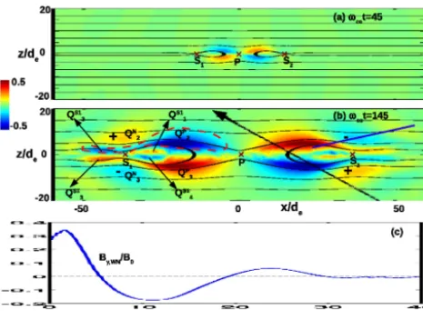
de-Figure 1. Magnetic field lines (black) plotted over color-codedBy atωcet=45 (a) and =145 (b). The primary (P) and secondary (S1 andS2) sites are marked by crosses (×S). Atωcet=145, outward oblique propagation of whistlers from secondary sites forms a new quadrupole, marked with “+” and “–”. In (b), the poles of primary, secondary and new quadrupoles are marked by Q’s (see text for def-inition) in the left half. The red dashed loop encloses a negative pole of the extended quadrupole. The blue line in the top right quadrant is at an angle of 19.5◦with the background magnetic field along
+x and approximates the wave normal. The profile ofBy along the wave normal is shown in (c). The black line with an arrow in (b) shows a possible trajectory of the Cluster spacecraft.
scribed using an electron-magnetohydrodynamic (EMHD) model (Kingsep et al., 1990). In the observations, the typi-cal gyro-radius for 100 eV electrons is estimated to be 10 km (≈de/2) in the magnetic field of 3 nT. The half-thickness of the ECS in the observations is 3–5 electron inertial lengths, which is 6–10 times larger than the electron gyro-radius. Moreover, the magnitude of the magnetic field is never zero during the current sheet crossing (Fig. 3a in Wygant et al., 2005). The gyro-radius of 100 eV electrons for the minimum magnitude of magnetic field (≈1 nT) is 30 km, which is ap-proximately 2–3 times smaller than the half-thickness of the ECS. In the observations, ions are demagnetized and decou-pled from electrons (Wygant et al., 2005). These considera-tions show that a fluid approximation at electron scales, viz. electron-magnetohydrodynamics, can be applied to describe the Cluster observations.
[image:2.612.311.544.64.245.2]Although Cluster did not cross the X point, kinetic pro-cesses near the X point, e.g., meandering orbits of electrons, or near the weak field regions on the spacecraft trajectory may influence the dynamics. However the excellent agree-ment of EMHD simulations with the observations, as we show, indicates that the essential physics are captured by EMHD model.
Figure 2. Observation of electron-scale current sheet by Cluster (adopted from Fig. 3a of Wygant et al., 2005). Top panel:EyGSE (y component of electric field in GSE coordinate system). Three bottom panels:x,yandzcomponents of magnetic field in bound-ary normal coordinate system. Vertical dashed lines (L1−L4) mark the zero crossings of the magnetic field components.
2 Nested quadrupole structure of the Hall field
Spontaneous reconnection at multiple sites in an ECS devel-oping into primary and secondary sites (Jain and Sharma, 2009), shown in Fig. 1, is modeled using EMHD simula-tions. Here length is normalized by de, magnetic field by the asymptotic value B0, and time by ω−ce1=(eB0/me)−1. Fig. 1a shows the structure of the Hall fieldBy in the early stage (ωcet=45), which evolves into the late stage (ωcet= 145), shown in Fig. 1b. At ωcet=45 the reconnection is dominant at the primary site (P) in the center of the simu-lation domain (x=z=0). The field lines reconnected at the primary siteP reconnect again at the secondary sites (S1at
x≈ −16de andS2 atx≈16de), giving rise to reconnec-tion at multiple sites. The quadrupole structure of the out-of-plane magnetic field is clearly developed around the primary site, while it is not yet recognizable at the secondary sites. At
ωcet=145, the central site remains dominant and the sec-ondary sites are pushed away by the outflows from the cen-tral site. We label the quadrupole Hall fields associated with
S1,S2 andP as QS1,QS2 and QP, respectively. The new quadrupole, marked asQN, forms due to the interactions of the inflow to the secondary sites and the outflow from the pri-mary site (Jain and Sharma, 2009). The poles of a quadrupole are numbered counterclockwise beginning with 1 for the top right pole to 4 for the bottom right pole. An individual pole of a quadrupole is represented by a subscript toQ’s. For ex-ample,QS1
1 represents the top right pole of the quadrupole associated with the reconnection siteS1. The poles of the pri-mary, secondary and new quadrupoles are marked only in the left half of Fig. 1b. The polesQS1
1 andQ S1
[image:2.612.52.285.66.237.2]quadrupole atS1penetrate between the polesQP2 andQP3 of the primary quadrupole. At the same time, the polesQS1
2 and
QS1
3 of the secondary quadrupole atS1connect to the poles
QP2 andQP3 of the primary quadrupole, respectively, thus in-creasing the extent of the primary quadrupole QP. One of the negative poles (QP2+QS1
2 ) of the extended quadrupole is enclosed by a closed loop (red dashed line) in Fig. 1b. The ex-tended quadrupole is nested inside the new quadrupole (QN), the poles of which are also marked (“+” and “–”) in Fig. 1b.
A striking feature of spontaneous reconnection at multi-ple sites is the new quadrupole, which, unlike the other three quadrupoles in Fig. 1b, is not directly associated with a re-connection site but arises from their interaction. The physics of the new quadrupole are the whistler response of the up-stream plasma to the interaction of inflow to the secondary (weak) sites and outflow from the primary (dominant) site (Jain and Sharma, 2009). Because of the magnetic field struc-ture of reconnection, the whistler perturbations are anchored in phase at their origin and propagate away from the recon-nection region. The direction of propagation is very well ap-proximated by the wave normal (shown by the blue line in Fig. 1b), which is at a Storey angle of 19.5◦ (Storey, 1953; Singh, 2011) with the background magnetic field along x. Figure 1c shows the out-of-plane magnetic fieldBy,WNalong the wave normal. The wave propagates away from the re-connection region while its amplitude diminishes. The dis-tance between positive and negative peaks is ≈12de, giv-ing a wave number k de≈0.25, as expected for frequency
ω=0.1ωce (Singh, 2007). The extension of the primary quadrupole alongx and the formation of a new quadrupole due to the whistler perturbation at secondary sites in the man-ner described above make the overall structure a nested struc-ture of quadrupoles.
The EMHD simulations are of the early phase of recon-nection, in the sense that the results are valid for a short time (less than the ion cyclotron time) after the development of the instability in the ECS. However the results are in general valid for the later stage as well because the spatial structures arise mainly from the whistler eigenmode, which will persist with modifications due to coupling to ions, other modes and inhomogeneities.
3 Cluster observations of nested quadrupole
[image:3.612.309.546.68.228.2]The Cluster spacecraft crossed the reconnection region at dis-tances of∼18REin Earth’s magnetotail on 1 October 2001. Among the four spacecraft, SC4 was closest to the X line and crossed the current sheet on the earthward side between 09:46:48 and 09:46:51 UT, and the profiles of electric and magnetic field are shown in Fig. 2 (Fig. 3 in Wygant et al., 2005). The change in sign of the magnetic field components is critical to the structure of the Hall field, and the time marks for these are shown by the vertical dashed lines in Fig. 2, viz.L1forBz,L2forBy,L3forBz, andL4forBxandBy.
Figure 3. A schematic of reconnection at a primary (P) and a sec-ondary (S) sites. Components of the magnetic field in thex and zdirections are shown by red arrows at select locations (A, B, C, D and E) on a spacecraft trajectory (black dashed line). The sign of the out-of-plane magnetic fieldByin the regions of interest is represented by color-shaded (positive by reddish and negative by blueish) regions. The locations of zero crossings of the magnetic field components, marked by linesL1−L4in Figs. 2 and 4, are approximately indicated on the trajectory by filled circles.
Figure 4. Simulated electric and magnetic field profiles along the trajectory shown in Fig. 1b. Top panel: theycomponent of the elec-tric field (EyGSE, blue) transformed from the simulation or bound-ary normal to GSE coordinate system, the normal component (red) and current-aligned (black) electric field ofEyGSE. Also shown is the boundary normal vector in theyGSE−zGSEplane. Three bottom panels: thex,yandzcomponents of the magnetic field in boundary normal coordinate system. Vertical dashed lines (L1−L4) mark the zero crossings of the magnetic field components.
S (see Fig. 3). It then encounters the field lines of the mag-netic islands formed due to the reconnection both at P and
S, first in the region below the plane containing the primary and secondary sites, viz. the south lobe (at points B, C and D), and then in the north lobe (at point E). SinceBzchanges sign from positive at A to negative at B while Bx<0 and
By>0 both at A and B, the first zero crossing ofBz(marked by line L1 in Fig. 2) must be somewhere between A and B as shown in Fig. 3. By looking at the signs of the magnetic field components, the approximate locations of their other zero crossings, marked by lines L2, L3 and L4 in Fig. 2, can be identified on the virtual spacecraft trajectory as shown in Fig. 3.
For comparison with Cluster observations, Fig. 4 shows the simulation profiles of electric and magnetic fields (in un-normalized units usingB0=10 nT andde=20 km for Clus-ter observations) along the trajectory shown in Fig. 1b, as functions of distance along the trajectory. Similar to Fig. 2, the vertical dashed lines in this figure mark the zero cross-ing ofBxatL4,ByatL2andL4, andBzatL1andL3. The profiles of they component of electric field and all compo-nents of magnetic field in Fig. 2 are in the geocentric solar ecliptic (GSE) and boundary normal coordinate systems, re-spectively. In the boundary normal coordinate system, zis normal to the current sheet surface,y is along the direction of current and(x, y, z)forms a right-handed coordinate sys-tem. Since the simulations are in boundary normal coordinate system, the profile of the electric field in Fig. 4 is obtained
by transforming it from boundary normal to the GSE system. The boundary normal vectornˆ= −0.05xˆGSE+0.80yˆGSE− 0.59zˆGSE of the highly tilted current sheet in Cluster obser-vations is almost in theyGSE−zGSEplane and shown in the top panel of Fig. 4. Assuming the current sheet in the simu-lations to have the same orientation with respect to the GSE coordinate system, theycomponent of the electric field in the latter can be obtained fromEyGSE=Eysin(α)−Ezcos(α), whereαis the angle between the normal vector and theyˆGSE, with cos(α)=0.8.
The electric and magnetic field profiles in the Cluster ob-servation (Fig. 2) and EMHD simulation (Fig. 4) are remark-ably similar not only in magnitude but also in the scale and pattern of variation. The current sheet crossing, represented by the change inBxfrom≈ −10 to≈10 nT in observations (during∼46:48−46:51, Fig. 2) and simulations (Fig. 4), provides more details on the reconnection in the magnetotail. The half-thickness of the current sheet in simulations≈7de compares well with the observed values∼3−5de. The step-like structures ofBxinside the current sheet are present both in simulations and observations, and indicate a filamentary structure in the current sheet.
Associated with the current sheet crossing,EyGSEand Hall field By have bipolar forms that change their signs from negative to positive. The positive and negative peaks of the bipolar structures ofEyGSE andByin observations and sim-ulations are very similar. Consistent with the observations, Fig. 4 shows that EyGSE, given by Eysin(α)−Ezcos(α), is dominated by the normal component of the electric field,
Ezcos(α), due to the tilt of the current sheet with respect to the GSE coordinate system.
The normal component of magnetic fieldBzremains pos-itive during the current sheet crossing but is negative just be-fore the current sheet crossing (betweenL1andL3). The zero crossing ofBzatL3 coincides with the edge of the current sheet and negative peaks ofEyGSEandBy. BothBzandBy have positive values before their first zero crossings atL1and
L2, respectively. In the simulations, the positive By on the left ofL2 is due to the crossing of a positive pole (marked by “+” on the positivex side in Fig. 1b) of the new (outer) quadrupole structure ofBy. The positiveByon the left ofL2 in Fig. 2 can be identified with the new quadrupole, and the Cluster observation is consistent with a nested quadrupole structure of the out-of-plane magnetic field. Note that the peak value ofBy on the left ofL2 is≈30 % of the largest peak of the observedByand is thus significant and due to the physical electron-scale processes.
With higher resolution measurements of the fields, e.g., from NASA/MMS mission, these issues are likely to be resolved. Also, the electron measurements could be used to compare with the flows seen in the simulations to complement the magnetic field data.
4 Discussion and conclusions
The formation of the nested structure of quadrupoles of the Hall magnetic field requires not only the presence of multiple sites but also the dominance of one site over the neighbor-ing sites. Simulations with three reconnection sites of equal strength (excited by initializing the simulations with a single wavelength perturbation with three wavelengths fitting in the length of the simulation box alongx) show that the out-of-plane magnetic field does not develop a nested structure of quadrupoles. Although the quadrupole structure ofByforms at each reconnection site, the inflow to one site and outflow from the neighboring site do not interact in the manner that results into the nested quadrupole structure. In natural situa-tions, e.g., in the magnetotail, reconnection at multiple sites is expected, with the one initiated first being dominant over the adjacent sites. Further, in the magnetotail, the monotonic decrease in the magnetic field away from Earth (alongx) will introduce asymmetry among the multiple reconnection sites, thus leading to the nested Hall field.
In the Cluster observations, the total time of crossing (≈6 s) is close to the ion cyclotron period and thus cap-tured the electron-dominated physics of reconnection. Since these electron-scale observations are by a single spacecraft when the other three spacecrafts were separated by distances much larger than typical electron scales (∼20 km), the spa-tial and temporal variations are not uniquely distinguished. However, the EMHD simulations show that the electron-scale structures form very quickly, in a time of the order of tens of electron cyclotron periods, but evolve very slowly af-ter their formation (Jain and Sharma, 2009). Thus the struc-tures observed by Cluster are consistent with spatial varia-tions as described above. The forthcoming multi-spacecraft NASA/MMS mission, designed to resolve the electron scales in the magnetosphere and to distinguish between spatial and temporal variations, will provide key details of the spatiotem-poral structure.
In conclusion, the nested quadrupole structure of the Hall magnetic field is identified in Cluster observations and the underlying mechanism is revealed by EMHD simulations of an ECS. Many details of the electron-scale physics and the connection to the larger-scale ion processes remain yet un-explored. Such studies will require new studies of electron-scale physics in simulations, experiments and satellite obser-vations of magnetic reconnection. In particular, the results presented in this paper provide a critical step for a deeper understanding of reconnection at electron scales using new kinetic simulations that resolve the electron scales clearly
and the data for electron-scale physics from the upcoming NASA/MMS mission.
Acknowledgements. This research was supported by NSF grant
AGS-1027185.
The article processing charges for this open-access publication were covered by the Max Planck Society.
The topical editor E. Roussos thanks one anonymous referee for help in evaluating this paper.
References
Asano, Y., Mukai, T., Hoshino, M., Saito, Y., Hayakawa, H., and Nagai, T.: Current sheet structure around the near-Earth neu-tral line observed by Geotail, J. Geophys. Res., 109, A02212, doi:10.1029/2003JA010114, 2004.
Attico, N., Califano, F., and Pegoraro, F.: Fast collisionless recon-nection in the whistler frequency range, Phys. Plasmas, 7, 2381, doi:10.1063/1.874076, 2000.
Borg, A. L., Oieroset, M., Phan, T. D., Mozer, F. S., Peder-sen, A., and Mouikis, C.: Cluster encounter of a magnetic reconnection diffusion region in the near-Earth magnetotail on September 19, 2003, Geophys. Res. Lett., 12, L19105, doi:10.1029/2005GL023794, 2005.
Chen, L. J., Bessho, N., Lefebvre, B., Vaith, H., Fazakerley, A., Bhattacharjee, A., Puhl-Quinn, P. A., Runov, A., Khotyaintsev, Y., Vaivads, A., Georgescu, E., and Torbert, R.: Evidence of an extended electron current sheet and its neighboring magnetic is-land during magnetotail reconnection, J. Geophys. Res., 113, A12213, doi:10.1029/2008JA013385, 2008a.
Chen, L. J., Bhattacharjee, A., Puhl-Quinn, P. A., Yang, H., Bessho, N., Imada, S., Muhlbachler, S., Daly, P. W., Lefebvre, B., Khotyaintsev, Y., Vaivads, A., Fazakerley, A., and Georgescu, E.: Observation of energetic electrons within magnetic islands, Na-ture Phys., 4, 19–23, doi:10.1038/nphys777, 2008b.
Daughton, W., Scudder, J., and Karimabadi, H.: Fully kinetic sim-ulations of undriven magnetic reconnection with open boundary conditions, Phys. Plasmas, 13, 072101, doi:10.1063/1.2218817, 2006.
Hesse, M., Birn, J., and Kuznetsova, M.: Collisionless magnetic re-connection: Electron processes and transport modelling, J. Geo-phys. Res., 106, 3721, doi:10.1029/1999JA001002, 2001. Jain, N. and Sharma, A. S.: Electron Scale Structures in
Colli-sionless Magnetic Reconnection, Phys. Plasmas, 16, 050704, doi:10.1063/1.3134045, 2009.
Kingsep, A. S., Chukbar, K. V., and Yan’kov, V. V.: Reviews of Plasma Physics, vol. 16, Consultants Bureau, New York, USA, p. 243, 1990.
Mandt, M. E., Denton, R. E., and Drake, J. F.: Transition to Whistler Mediated Magnetic Reconnection, Geophys. Res. Lett., 21, 73– 76, doi:10.1029/93GL03382, 1994.
Singh, N.: Group velocity cones in diverging magnetic re-connection structures, J. Geophys. Res., 112, A07209, doi:10.1029/2006JA012219, 2007.
Singh, N.: Whistler mode based explanation for the fast reconnec-tion rate measured in the MIT Versatile Toroidal Facility, Phys. Rev. Lett., 107, 245003, doi:10.1103/PhysRevLett.107.245003, 2011.
Sonnerup, B. U. O.: in Solar System Plasma Physics, vol. 3, North-Holland, Amsterdam, the Netherlands, 1979.
Storey, L. R. O.: An investigation of whistling atmo-spherics, Phil. Trans. Roy. Soc. Ser. A, 246, 113–141, doi:10.1098/rsta.1953.0011, 1953.
Wang, R., Lu, Q., Du, A., and Wang, S.: In Situ observations of a secondary magnetic island in an ion diffusion region and associted energetic electrons, Phys. Rev. Lett., 104, 175003, doi:10.1103/PhysRevLett.104.175003, 2010.