Available Online at www.ijpret.com
510
INTERNATIONAL JOURNAL OF PURE AND
APPLIED RESEARCH IN ENGINEERING AND
TECHNOLOGY
A PATH FOR HORIZING YOUR INNOVATIVE WORK
ERROR CORRECTION SYSTEM USING ARTIFICIAL NEURAL NETWORK
MADHUSUDAN G. LANJEWAR
University Science Instrumentation Centre (USIC), Goa University, Goa-403206
Accepted Date: 27/02/2014 ; Published Date: 01/05/2014
\
Abstract:The use of error correcting code has proved to be an effective means to overcome data corruption in digital communication channels. In digital communication, Convolutional encoder is widely used for error correcting of data which transmitted through the noisy channel. The Viterbi decoder is used for decoding Convolutional encoded data. Viterbi decoding consists of computing the metric for two paths in the Trellis diagram and eliminating one which is of higher value. A peculiar situation arises when two metrics have the same value. In this case, the decoder selects an arbitrary bit. This ambiguous situation is eliminated using neural network. The Adaptive Resonance Theory-1 (ART-1) has been developed to avoid the stability-plasticity dilemma in competitive networks learning. The stability-plasticity dilemma addresses how a learning system can preserve its previously learned knowledge while keeping its ability to learn new patterns. The Convolutional encoder has been designed using Shift register, mod-2 adders and a commutator. It is interfaced with the Personal Computer through the Centronic port for decoding. The ART-1 algorithm has been implemented in “C” Language. The ART-1 based decoding program decodes the encoded data from the Convolutional encoder. The output of ART-1 based decoder exactly matches the data input to the encoder.
Keywords: Artificial Neural Network (ANN), Convolutional Encoder, Vitebi Decoding Algorithm, ART-1.
Corresponding Author: MR. MADHUSUDAN G. LANJEWAR
Access Online On:
www.ijpret.com
How to Cite This Article:
Madhusudan Lanjewar, IJPRET, 2014; Volume 2 (9): 510-519
Available Online at www.ijpret.com
511
INTRODUCTION
The purpose of forward error correction (FEC) is to improve the capacity of a channel by adding some carefully designed redundant information to the data being transmitted through the channel [1,2]. The process of adding this redundant information is known as channel coding. One of the widely used for error correction of data consists of convolutional coding with Viterbi decoding algorithm. The ambiguous situation arising in the Viterbi decoder is eliminated when the artificial neural network (ANN) is used for decoding of data. This paper will primarily focus on the Adaptive Resonance Theory-1 (ART-1) which one of the model of Artificial Neural Network (ANN). The following sections will describe algorithms for generating random binary data, convolutionally encoding the data, passing the encoded data through a noisy channel, quantizing the received channel symbols, and performing ART-1 based decoding to recover the original binary data.
a. Viterbi Decoding
Decoding algorithm used with convolutional encoding is the Viterbi decoding developed by Andrew J Viterbi. It is based on the principle of maximum likelihood of events [1, 2]. The maximum likelihood receiver implies selecting a code word closest to the received word. Basically, Viterbi decoding consists of computing the metric for two paths in the Trellis diagram and eliminating one, which has higher value. The decoding is based on the Trellis diagram. The algorithm involves calculating the hamming distance between the received signal and the entire trellis path entering each state [2,3]. When two paths enter the same state, then one having the best metric (the surviving path) is chosen; for all states. The decoder continues in this way to advance deeper into the trellis diagram [4, 5]. The Viterbi decoder is implemented either by using hardware circuits or a software program. In the peculiar situation when two metrics have the same value the decoder selects the arbitrary bit. This ambiguous situation is eliminated using neural network in the Viterbi decoder.
b. Adaptive Resonance Theory – 1 (ART-1)
Available Online at www.ijpret.com
512
stability-plasticity dilemma addresses how a learning system can preserve its previously learned knowledge while keeping its ability to learn new patterns [8, 9, 10].
II. Design and Methodology
a. Convolutional Encoding
Convolutionally encoding of the data is accomplished using a shift register and associated combinatorial logic that performs modulo-two addition. A typical convolutional encoder of constraint length N=3, rate= ½, and vector connection code (111,101) is shown in figure 1. The input bits are stored in fixed length shift registers and they are combined with the help of mod-2 adders. Whenever the message bit is shifted to position ‘m’ the new values of ‘v1’ and ‘vmod-2’ are generated depending upon m, m1 and m2. The m1 and m2 store previous two message bits. The current bit is present in ‘m’. Thus we can write:
V1=m ^ m1^ m2 (^ - ExOR operation)
V2=m ^ m2
Fig-1: convolutional encoder N=3, rate =1/2, code conversion vector (111,101)
Available Online at www.ijpret.com
513
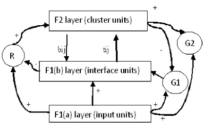
Fig 2: Structure of supplemental units of ART-1
Fig 2 shows the Structure of supplemental units of ART-1. It involves three groups of neurons.
1) Input processing field – F1 layer
2) Cluster units – F2 layer
3) Reset mechanism – that controls the degree of similarity of patterns placed on the same cluster.
Binary input vector is presented to F1(a) layer and is then received by F1(b). The F1(b) layer
sends the activation signal to F2 layer over weighted interconnection path. Each F2 will calculate
the net input. The unit with largest net input will be the winner that will have activation d=1. All other units will have activation as zero. That winning unit alone will learn the current input pattern. The signal sent from F2 to F1(b) through weighted interconnections is called as
top-town weight. The X unit remain ‘on’ only if they receive non-zero weight from both the F1(a)
and F2 units. The norm of the vector ||x|| will give the number of components in which
top-down weight vector for the winning unit (tij) and the input vector S are both ‘1’. Depending
Available Online at www.ijpret.com
514
III. Experimental Work
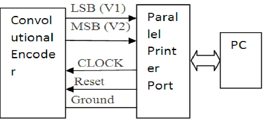
a. Complete error correcting System
Fig 3 Covolutional encoder interface with PC
The convolutional encoder is interface with PC through parallel printer port as shown fig 4. The explanation of each block is as follows:
Available Online at www.ijpret.com
515
Fig 4 circuit diagram of convolutional encoder
Fig 3 shows the circuit diagram of convolutional encoder. It consists of shift register, mod-2 adder and commutator IC’s. The clock is generated from PC through PPP. IC 7490 (decade counter) as a mod-8 counter for generating clock to the IC 74393 and selecting data input for IC 74151 (8:1 MUX). IC 74393 (8-bit counter) is used for generating combination of 8-bits which serve as the data input for IC 74151. IC 74151 is used for selecting a data input or also called as sequence generator. IC 7474 (D flip flop) as a shift register which takes the data from the IC 74151 and give to the next 7474 IC. IC 7486 (XOR gate) is used for XO Ring the output of IC 7474. There are three 7474 IC’s and two XOR gates. The output of XOR gate (V1 & V2) are given to ART-1 based decoder which is stored in PC through parallel printer.
c. ART-1 Algorithm
The training algorithm of ART-1 network as follows:
Step 1: Initialize parameters L>1 and 0 ≤ ρ ≤ 1. Initialize weights 0 < bij(0)L/(L-1+n), tij=1
Step 2: while stopping condition is false, perform Steps 3-14
Step 3: for each training input, do steps 4-13.
Step 4: Set activations of all F2 units to zero.
Set activations of F1(a) units to input vector s.
Step 5: Compute the norm of s: ||s||= ∑i
Si
Step 6: send input signal from F1(a) to F1(b) layer , xi=si
Step 7: for each F2 node that is not inhibited.
If yj≠ -1, then yj=
∑ i
bij Xi
Step 8: while reset is true, perform step 9-12
Step 9: find J such that yJ≥yj for all nodes j
If yj= -1, then all the odds are inhibited and this pattern cannot be clustered
Step 10: Re-compute activation x of F1(b). Xi=si tJi
Step 11: Compute the norm of vector
Available Online at www.ijpret.com
516 Step 12: Test for reset, If (||x||/||s||)< ρ, then yJ=-1(inhibit node J) (and continue executing
step again) if (||x||/||s||)≥ ρ, then proceed to step- 13
Step 13: Update the weights for node J
bij(new)=Lxi/(L-1+||x|| ), tJi(new)=xi
Step 14: test for stopping condition
The stopping condition may be no weight changes, no units reset or maximum number of epochs searched. In winner selection, if there is a tie, take J to be the smallest such index. Also tji is either 0 or 1, and once it is set to 0 during learning, it can be never set back to 1 because of
stable learning method. The typical values of parameters are given in table 1 and flowchart of ART-1 algorithm shown in fig 4.
TABLE 1: Typical values of parameters used in ART-1 algorithm
Parameter Range values
L L>1 2
Ρ 0 ≤ ρ ≤ 1 ( vigilance parameter) 0.9
bij 0<bij(0)<L/(L-1+n)(bottom-up weights) 1/1+n
tji tji(0)=1 (top down weights) 1
Available Online at www.ijpret.com
517
IV. Results and Discussion
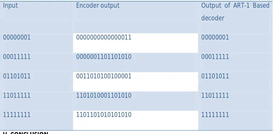
The encoder has the constraint length N=3 and vector connection code [111101] for mod-2 adders. 16-bit output sequence is generated corresponding to the input data bits. The Convolutional encoder has some special features as follows: Input data are generated by the counter system. Clock required is obtained from the computer’s parallel printer port (Centronic) using the instruction outport. Reset signal is generated by computer “C” programming [19,20]. Reset is used instead of including dummy bits into input data stream. The ART-1 based decoding program decodes the encoded data from the convolutional encoder. The output of ART-1 based decoder exactly matches the data input to the encoder. The inputs for the ART-1 based decoder are a 8-bits, 16-bits or 32-bits. The output of the decoder exactly matches with the data input to the encoder as seen in table 2.
Table 2. Input-Output data display
Input Encoder output Output of ART-1 Based
decoder
00000001 0000000000000011 00000001
00011111 0000001101101010 00011111
01101011 0011010100100001 01101011
11011111 1101010001101010 11011111
11111111 1101101010101010 11111111
V. CONCLUSION
Available Online at www.ijpret.com
518
REFERENCES:
1. Lathi B P, “Modern Digital & Analog Communication System”, Oxford University Press, 3rd edition, 1998.
2. Chitode J S, “Digital Communication”, Technical Publication, Pune, 3rd Revised Edition, 2002
3. S. Lin and D. J. Costello, Jr., Error Control Coding: Fundamentals and Applications, second edition, Prentice Hall: Englewood Cliffs, NJ, 2004.
4. W.W. Peterson and E.J. Weldon, Jr., Error-Correcting Codes, 2nd edition, MIT Press: Cambridge, Mass., 1972.
5. F.J. MacWilliams and N.J.A. Sloane, The Theory of Error-Correcting Codes, North-Holland: New York, NY, 1977.
6. James A. Freeman & David M. Skapura, “Neural Networks – Algorithm, Applications & Programming Techniques”, Pearson Education Asia, 2002.
7. Bose N K & Liang P, “neural Networks with graphs, Algorithms, Applications”, TATA McGRAW Hill Edition, 2nd edition 2001.
8. Kishan Meharotra, Chilukuri K. Mohan & Sanjay Ranka, “Elements of Artificial Neural Network”, The MIT Press, 1997, USA.
9. Chen Haixia, “Study on Adjustment of learning rate and Its Application of ART2”, International Conference on intelligent Computation Technology and Automation 2008.
10.L.G. Heins & D.R. Tauritz, “Adaptive Resonance Theory (ART): An Introduction” May/June 1995
11.Kishan Meharotra, Chilukuri K. Mohan & Sanjay Ranka, “Elements of artificial Neural Network”, The MIT Press, 1997, USA.
12.B. Govindarajalu: IBM PC and Clones: Hardware, Troubleshooting and Maintenance, TMH, New Delhi, Ch. 3, pp. 63-102 (1998)
13.Keithley, Data acquisition and control Handbook, first edition, 2001.
Available Online at www.ijpret.com
519