Please cite this article as:A. Nakhaei, M. Dardel, M. Ghasemi, M. Pashaei,A Simple Method for Modeling Open Cracked Beam, International Journal of Engineering (IJE), TRANSACTIONS B: Applications Vol. 28, No. 2, (February 2015) 321-329
International Journal of Engineering
J o u r n a l H o m e p a g e : w w w . i j e . i r
A Simple Method for Modeling Open Cracked Beam
A. Nakhaei, M. Dardel*, M. Ghasemi, M. Pashaei
Department of Mechanical Engineering, Babol Noshirvani University of Technology, Babol, Iran.
P A P E R I N F O
Paper history: Received 24 March 2014
Received in revised form 07 July 2014 Accepted 13 November 2014
Keywords:
Crack
Lumped Stiffness Model Step Beam
Natural Frequency Mode Shape
A B S T R A C T
A simple method is proposed to model the open cracked beam structures. In this method, crack is modeled as a beam element. Hence cracked beam can be assumed to be a beam with stepped cross sections, and problem of determining natural frequency and mode shape of cracked beam, can be solved as determining these characteristics for a beam with different lengths and cross sections. With this work, it is not necessary to model crack as lumped flexibility model in according to fracture mechanics and related sciences to obtain crack stiffness, and this spring model of crack can be used for further analysis.
doi: 10.5829/idosi.ije.2015.28.02b.20
1. INTRODUCTION1
The presence of a crack in structural members decreases their stiffness and natural frequencies. We can group different models of cracked structure in three basic categories [1]: equivalent reduction in local stiffness (smeared crack models), lumped flexibility models, and continuous cracked bar and beam models. A smeared crack model usually consists of a finite element model of the structure in which the damage is represented by an equivalent reduction in the stiffness of a particular element or group of the elements. Better representations of the effect of a crack over a region may be achieved by developing special finite elements, as reported by Haisty and Springer [2] and Gounaris and Dimaroginas [3]. Ibrahim [4] proposes an elasto-plastic finite element capable of accounting for the plastic deformation at the crack tip. Lumped flexibility models are based on sub-structuring concept. The undamaged portions of the structure are modeled using standard techniques such as FEM, component mode synthesis, or partial differential equations, and the crack is represented by lumped springs or by a compliance matrix, usually derived from the expression for the strain energy release rate or stress
1*Corresponding Author’s Email:[email protected] (M. Dardel)
intensity factor. The first investigations are attributed to Kirmser [5]. They represented the effect of a notch by equivalent forces and moments at the location of the geometrical discontinuity. Dimarogonas [6] proposed the derivation of compliance constants from fracture mechanics and used it for vibration analysis. Christides and Barr initially developed models for transverse vibrations of a symmetric, double-edge cracked Euler-Bernoulli beam [7] and for the torsional vibrations of a cracked bar [8]. Both models rely on the characterization of the stress concentration due to the crack by means of a decay function. The mixed variational theorem used is an extension of the Hu-Washizu stationary principle[9], and it is now referred in the literature as the Hu-Washizu-Barr [10] principle. Christides and Barr’s model was improved and extended in following years by Shen ad Pierre [11-13], first by introducing an alternative estimation of the decay parameter from 2D finite element models and later by applying the same ideas to develop a model for beams with a single edge breathing crack. Chondors and Dimarogonas [14-17] used a similar variational approach, but they derived the so-called crack functions from energy considerations and fracture mechanics concepts.
Studies on nonlinear behavior of cracked beam using perturbation models have been proposed, e.g., by Gudmundson [18], Tsyfanskii [19], Plakhtienko and Yasinskii [20] and Ballo [21]. A review on the vibration analysis for a damage occurrence of a cantilever beam is given by Jassim et al. [22]. AL-Shudeifat used finite element modeling approach to study asymmetric cracked rotor [23]. Dynamic behavior of single-cracked beams considering the effects of axial stiffness, and shear deformations is carried out by Gomes and Almeida [24]. The damage is modeled using a rotational spring that simulates the crack based on fracture mechanics theory. Caddemi and Morassi investigate mathematical modeling and exact solutions of multi-cracked Euler–Bernoulli beams [25]. Dixit and Hodges, gave a general formulation termed the “Unified Framework”, which yielded nth-order expressions governing mode shapes and natural frequencies for damaged elastic structures such as rods, beams, plates and shells of any shape [26]. Rakideh et al. presented identification of crack location in beams with different boundary conditions based on neural network method [27].
The most used method for modeling vibration characteristics of cracked beam is the lumped flexibility model. In this model, the cracked section is considered as a torsional (rotational) spring. The stiffness of this spring is obtained from fracture mechanics, in which boundary conditions, location, opening (or length) of the crack is not important. Here a method is presented for modeling of crack, in which all of these parameters are considered in modeling of crack. In the proposed method, crack is modeled as a beam element. Hence a cracked beam can be assumed to be a beam with stepped cross sections, and problem of determining natural frequency and mode shape of cracked beam, can be solved as determining these characteristics for a beam with different cross sections. With this work, it is not necessary to model crack in according to fracture mechanics. With this modeling method, position, width and height of cracks are directly included in modeling. With putting aside fracture mechanics from analysis, modeling of crack will be simple, and analytical solution of crack problem will be possible.
2. MODELING OF CRACKED BEAM
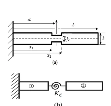
Figure 1 (a) shows a beam of length L and thickness
h , containing an edge crack of depth hc located at a distances x1 and x2 from the left end, and the middle point of the crack is (x1+x2) / 2 which is assigned as
eL, Young's modulus of elasticity E and mass density
r are assumed to be constant.
3. LUMPED MODELING OF CRACK
The lumped flexibility form for modeling cracked beam is simply shown in Figure 1 (b). In this simple model, the crack is modeled by massless spring with rotational (torsional) stiffness of KC. The effects of
discontinuities in axial and transverse displacements are considered to be negligible compared with those of discontinuity in bending slope. The cracked beam is divided into two sub-beams connected by the rotational spring with stiffness of KC at the cracked section whose
bending stiffness can be given as: 1
C
K G
= (1)
where, G is the flexibility due to the crack and can be derived as[28]:
( )
( )
2 2 2
1 1
2
K M dG
E a da
n
-= (2)
M, is the bending moment at the cracked section; K1 is the stress intensity factor (SIF) under mode I bending load; and E is Young’s modulus at the crack tip. The magnitude of SIF can be obtained from the data given in the literature [29] through Lagrange interpolation technique as:
( )
1 6M 2h , a ( 0.7)
K F
h bh
p h h h h
= = £ (3)
where, h£0.7 implies that crack depth ratio changes from 0.0 to 0.7, and:
( ) 2 3 4
5 6 7 8
0.6384 1.035 3.7201 5.1773 7.553 7.332 2.4909
F h h h h
h h h h
= - +
- + - + (4)
The expression of F( )h for other values of Young’s modulus ratios can also be obtained by using Lagrange interpolation formula. Substituting Equation (4) into Equation (3) and then into Equation (2) and integrating the results give:
( )
( )( )
2 2
2 0
72 1 F
G d
E h h
h p n h h
h h
-=
ò
(5)From Eqsuations (5) and (1), the bending stiffness of the cracked section required for lumped flexibility modeling can be determined.
4. CRACKED EULER-BERNOULLI BEAM WITH LUMPED FLEXIBILITY MODELS
Consider an elastic cracked Euler-Bernoulli beam of length L, uniform cross-section area A and moment of inertia I , with a crack at middle position of eLas shown in Figure 1. Differential equations of motion and boundary conditions on two segments of the beam are as follows:
(
EIw¢¢ +)
¢¢ rAw&&=0, 0< <x eL eL x L, < < (6)(0, )L 0, (0, )L 0
EIw w¢¢ ¢d = EIw w¢¢¢d = (7)
where, w x t( , ) is the beam transverse deflection and rmass density per unit length,A cross section area of beam, E Young’s module of elasticity and I is area moment of inertial. Also, at crack location:
( ), eL 0
eL eL eL
w + =w -=w eL EIw¢¢ +-= 0,
eL eL eL
c
eL eL eL
EIw¢¢¢ +- = EIw¢¢ +- =K w¢ +
-(8)
Following dimensionless parameter are defined:
4
, , i wi, ( 1, 2)
x EI
t i
L AL L
x t h
r
= = = = (9)
By substituting dimensionless parameter from Equation (9), in Equations (6) and (7), assuming harmonic solution as ( , ) i i
i Ae e
l x wt
h t x = , the related characteristic
equation will be obtained with eigenvalues of
2 2
1,2 , (i 1,2 )
l = ± = ±w b = . Then mode shape of beam has following form [30]:
1,2 1,5 2,6
3,7 4,8
Χ ( ) cosh sinh
cos sin
C C
C C
x bx bx
bx bx
= +
+ + (10)
Values of bi and the ratios of coefficients of mode
shapes ofC Ci/ 1, can be obtained from applying boundary and compatibility conditions at crack location.
5. CRACKED TIMOSHENKO BEAM WITH LUMPED FLEXIBILITY MODELS
Differential equations of motion and boundary conditions for transverse deflection w and slope of y
for beam in according to Timoshenko beam theory is as follows [30]:
For 0£ <x eL and eL x L< £ :
( )
( )
0, 0 Aw kAG w
I EI kAG w
r y
r y y y
¢¢ ¢ - - = ¢¢ ¢ - - - = && && (11)
and boundary conditions are:
( )
0,L 0, 0,L 0
EIy dy¢ = kAG w¢-y dw = (12)
and at crack location:
( ) ( )
, , , eLeL Kc eLeLw t eL w t eL w
EI y
+ +
-
-+ = - ¢ = ¢
( )eL ( )eL
kAG w¢-y +=kAG w¢-y
-(13)
where, w x t
( )
, is transverse deflection, and y( )
x t, is the slope of the deflection curve, G indicates shear modulus of elasticity. k represents the shear correction factor, which is assumed to be 5 / 6 . Following dimensionless quantities are introduced:2
4
, , , ,
i i
x kG r AL s r EI t
L E I AL
w L
x J J t
r
h
= = = = =
=
(14)
With assuming a harmonic solution in following form
( )
, Χi( ) ii ewt
h t x = x and y t xi
( )
, =Ψi( )xeiwt and obtainingi
Ψ( )x in terms of Χi( )x , we have [30]:
4 2 2
2 2
i i
i
4 2
Χ ω 1 1 Χ ω ω 1 Χ 0
s
d d
r s r
dx dx
æ ö
æ ö ç ÷
+ ç + ÷ + - =
ç ÷
è ø è ø (15)
in the form of Χi =Aei lx, the characteristic equation for determining of mode shape eigenvalue of l and mode shape will be obtained as:
2
2 2
1,2 ω ω4 1 1r s 1 ω2 1 1r s
l = æç - ö÷ + æç + ö÷
è ø m è ø (16)
( )
1,2 1,5 1 2,6 1
3,7 2 4,8 2
Χ cosh sinh
cos sin ,
C C
C C
x l x l x
l x l x
= +
+ +
( )
(
)
(
)
2
1,2 1 1,5 1 2,6 1
1 2
2 3,7 2 4,8 2
2
ω
Ψ ξ sinh cosh
ω sin cos C C s C C s
l l x l x
l
l l x l x
l
æ ö
ç ÷
=ç + ÷ +
è ø
æ ö
ç ÷
+ç - ÷
-è ø
(17)
( ) ( ) ( ) ( ) ( )
( ) ( )
1 2 2 1 1
2 1
2 1 2 1
1
Χ Χ , Χ Χ Ψ 0
Ψ( ) Ψ( ) 0,
Χ( ) Χ Ψ Ψ( ) 0
cb
e e e e e
K e e
e e e e
¢ ¢ ¢
= - - =
¢ - ¢ =
¢ - ¢ - + =
(18)
where,Kcb is given by following equation:
cb K
6 ( )
L h Fp h
= (19)
6. CRACKED EULER-BERNOULLI BEAM WITH CRACKS AS STEPPED CHANGE IN BEAM’S CROSS SECTION
As pointed out in the introduction section, here crack is modeled as a beam element with different cross sections other than intact section of beam. Hence a cracked beam as shown in Figure 1 can be modeled as three interconnecting beams, with different areas, moment of inertias, heights and lengths. Then intact and cracked segments of beam has area moment of inertia of
3 1/ 12
i i
I = bh and Ic=1/12b h h
(
- c)
3, respectively, whereh is the thickness of the beam and hc is the depth of the crack. The length of cracked beam segment is equal to its opening, i.e. x2-x1. The equation of motion for Euler-Bernoulli cracked beam is similar to Eqsuations (6) and (7), and related mode shape solution is similar to Equation (10). Then for a beam according to Figure 1 and with one crack, we have (from left end of beam):
4 4 i 4
4
3 4 2
Χ
Χ 0, ,
1 , 12
i i i i
i i i i
i d m bh d m L I bh EI q r x q w - = = = =
( ) 1, 2,
3, 4, 1
cosh sinh
cos sin ,
i i i i i
i i i i i i
W C C
C C x x x
x q x q x
q x q x
-= +
+ + £ £
(20)
For cracked section hi= -h hc. Since the value of
w(natural frequency) is high, for simplicity in numerical calculation it is better to select qi as unknown. The ratio of q qi/ 1 can be written as:
3
2 1 2
1 2 2 3
,
h h
h h
q q
q = q = (21)
and boundary and compatibility conditions at two ends of beam and location of cracks are:
1 10 3 31 1 10 3 31
Χ Χ¢¢d ¢ =0, Χ Χ¢¢d ¢ ,Χ Χ¢¢¢d =0, Χ¢¢¢dΧ =0
( ) ( ) ( ) ( )
1 1 2 1 1 1 2 1
Χ x =Χ x , Χ¢ x =Χ¢ x
( ) ( ) ( ) ( )
1 1 1Χ 2 2Χ 1 , 1 1 1Χ 2 2Χ 1
EI ¢¢x =EI ¢¢ x EI ¢¢¢x =EI ¢¢¢ x
( )
( )
( )
( )
2 2 3 2 2 2 3 2
Χ x =Χ x , Χ¢ x =Χ¢ x
(22)
( ) ( ) ( ) ( )
2 2Χ 2 3Χ 2 , 2 2Χ 2 3 3Χ 2
I ¢¢ x =I ¢¢x I ¢¢¢x =I ¢¢¢x
7. CRACKED TIMOSHENKO BEAM WITH CRACKS AS STEPPED CHANGE IN BEAM’S CROSS SECTION
Following the same procedure as described for Euler-Bernoulli beam, and with considering the crack as a beam with length equal to its opening and thickness equal to the thickness of the intact section minus depth of beam, following modeling of cracked beam in according to Timoshenko beam theory is given. The equation of motion for Timoshenko beam is given by Eqsuations (11) and (12), and related mode shape solution is also given by Equation (17). Then for a beam in according to Figure 1 and with one crack, we have:
(i=1, 2,3, 0£ <x x x1 1, < <x x x2 2, < £x 1): ( )
i ,1 ,1 ,2 ,1
,3 ,2 ,4 ,2
Χ cosh sinh
cos sin
i i i i
i i i i
C C
C C
x l x l x
l x l x
= +
+ +
2
i ,1 ,1 ,1 ,2 ,1
1 ,1 2
,2 ,3 ,2 ,4 ,2
1 ,2 ω
Ψ( ) sinh cosh
ω
sin cos
i i i i i
i
i i i i i
i
C C
s
C C
s
x l l x l x
l
l l x l x
l
æ ö
é ù
ç ÷
=ç + ÷ë + û
è ø
æ ö
é ù
ç ÷
+ç - ÷ë - û
è ø
(23)
Boundary and compatibility conditions for Timoshenko-beam are:
( ) ( )
( ) ( ) ( ) ( )
1 10 3 1
1 1 10 3 3 31
1 1 2 1 1 2 1
3
1
Ψ Ψ 0, Ψ Ψ 0
Χ Ψ Χ 0, Χ Ψ Χ 0
, Ψ Ψ
EI EI
kAG kAG
X X
d d
d d
x x x x
¢ = ¢ = ¢- = ¢- = = = ( ) ( ) 1 1 1 1
1 1 2 2
1 1 1 2 2 2
Ψ Ψ ,
Ψ Ψ
EI EI
kAG X kA G X
x x x x ¢ = ¢ ¢- = ¢ -( ) ( ) ( ) ( ) ( ) ( ) 2 2 2 2
2 2 3 2 2 2 3 2
2 2 3
2 3
3
2 2 3 3
, Ψ Ψ
Ψ Ψ ,
Ψ Ψ
X X
EI EI
kA G X kA G X
x x
x x
x = x x = x
¢ = ¢ ¢- = ¢ -( 2 4 )
It should be noted that formulation of the intact beam is similar to cracked beam, with putting aside the compatibility boundary conditions of cracked beam [30].
8. RESULTS AND DISCUSSIONS
4340 by the width,b=12.5 10 m´ -3 has been utilized for comparing the results. The mechanical and
geometrical parameters of cracked beam
are:L=1 m, /h L=0.25,r=7860 kg / m3, 210 GPa
E= . For the presented results acronyms of EB, TB, IB, PM and LM for Euler Bernoulli, Timoshenko beam, intact beam (without crack), present method and lumped method are selected, to simply referring the considered cases.
Table 1 shows predicted natural frequencies for cracked clamped-clamped (CC) beam for Euler-Bernoulli and Timoshenko theories, in according to the stepped beam and lumped flexibility methods for crack opening of d Lc/ =0.004. Natural frequencies of intact beam are shown in this table.
As seen from this table, there are very good conformity between these two results. From the results given in Table 1, it can be seen that natural frequency prediction in accordance to the lumped flexibility model presented in the literature [31] are lower than the results obtained from stepped change in cross section modeling of the beam, i.e. the amount of predicted stiffness reduction in according to lumped flexibility model is greater than stepped modeling of crack, although the difference between these two methods are very negligible. The accuracy of the presented modeling approach will be more clear in the following.
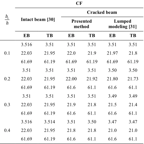
In Tables 2 and 3, three first natural frequencies of Euler-Bernoulli of free (CF) and clamped-simple (pined) (CS), are calculated for different values of crack’ depth. The crack location is assumed to be
0.5
h= and the opening of crack is d Lc/ =0.002. Natural frequencies of intact beam (IB) are shown for comparison. Again as seen from these results, there are very good conformity between these two different modeling of cracks, and this show the effectiveness of the proposed modeling method of crack.
TABLE 1. Three first natural frequencies for clamped-clamped beam, different crack depths and h=0.5,
/ 0.004 c
d L= .
c h h
Intact beam [30]
Cracked beam Lumped method
[31]
Presented method
EB TB EB TB EB TB
0.1
22.3 22.27 22.32 22.23 22.3 22.2 61.6 61.06 61.67 61.06 61.6 61.06 120.9 118.8 120.5 118.5 120.7 118.6
0.2
22.37 22.27 22.20 22.11 22.33 22.23 61.6 61.06 61.67 61.06 61.6 61.06
120 118 119 117 120 118.4
As expected with increasing depth of crack, natural frequencies of cracked beam are reduced, and with increasing or decreasing the rigidity of boundary conditions, natural frequencies are changed accordingly.
TABLE 2. Three first natural frequencies for CF beam, for crack location h=0.5, crack opening dc/L=0.002 and various crack depths.
c h
h
CF
Intact beam [30]
Cracked beam Presented
method modeling [31] Lumped
EB TB EB TB EB TB
0.1
3.516 3.51 3.51 3.51 3.51 3.51
22.03 21.95 22.0 21.9 21.97 21.8 61.69 61.19 61.69 61.19 61.69 61.19
0.2
3.51 3.51 3.51 3.51 3.50 3.50
22.03 21.95 22.00 21.92 21.80 21.73
61.69 61.19 61.6 61.1 61.6 61.1
0.3
3.51 3.51 3.51 3.51 3.49 3.49
22.03 21.95 21.9 21.8 21.5 21.4
61.69 61.19 61.6 61.1 61.6 61.1
0.4
3.516 3.514 3.51 3.50 3.47 3.47
22.03 21.95 21.8 21.8 21.0 21.0
61.69 61.19 61.6 61.1 61.6 61.1
TABLE 3. Three first natural frequencies for CS beam, for crack location h=0.5, crack opening dc/L=0.002 and
various crack depth
c h h
CS
Intact beam [30]
Cracked beam Presented
method
Lumped modeling [31]
EB TB EB TB EB TB
0.1
15.4 15.3 15.4 15.3 15.3 15.3
49.9 49.6 49.9 49.6 49.9 49.6
104.2 102.8 104.1 102.8 104.0 102.6
0.2
15.4 15.3 15.4 15.3 15.3 15.2
49.9 49.6 49.9 49.6 49.8 49.5
104.2 102.8 104.1 102.7 103.3 102.0
0.3
15.4 15.3 15.3 15.3 15.1 15.1
49.9 49.6 49.9 49.6 49.8 49.4
104.2 102.8 103.9 102.6 102.2 100.9
0.4
15.4 15.3 15.3 15.3 14.9 14.9
49.9 49.6 49.9 49.5 49.6 49.3
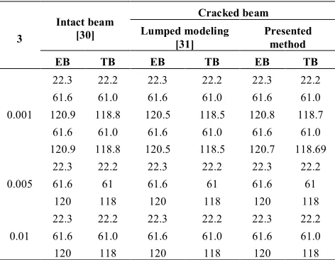
In Table 4, the effect of varying crack opening on three first natural frequencies of CC beam for crack location ofh=0.5 and depth ofh hc =0.1 is shown. From this table, it can be seen that for lower frequencies, natural frequencies predicted in according to lumped flexibility model of Euler-Bernoulli beam is greater than stepped modeling. While in higher models, lumped flexibility model gives higher prediction of natural frequency in comparison to present modeling of crack.
The effect of crack opening on natural frequency of Euler-Bernoulli's beam in according to these two mentioned methods of crack modeling will be more clear, with Tables 5. and 6. In these figures, three first natural frequencies of beams with different boundary conditions with one crack at location of h=0.5, depth of
0.5 c
h h= and different amounts of crack openings are shown. As expected, in all cases with increasing the crack opening, the amounts of natural frequencies are reduced. Now the effects of varying crack location on natural frequencies of beam are investigated. Table 7 shows the effect of crack location on natural frequency of beam. As seen from these tables, the differences between these two presented methods with varying the location of crack is more apparent in this case, i.e. change in location of crack. The amounts of differences are dependent to boundary conditions, and the amount of proximity of crack to the nodal point of related intact mode shape. In Figure 2, mode shapes and their slopes for three first natural frequencies of cracked CC beam obtained from stepped modeling of crack are shown. As seen from this figure, mode shapes and their slops are continuous in cracked section of beam, while there are qualitative change in the shape of slope of mode shapes in cracked section of beam, i.e.¶2w x/¶ 2 and ¶3w x/¶3 are discontinuous in the cracked domain.
TABLE 4. Three first natural frequencies for clamped-clamped beam (CC) for different crack openings,h=0.5 and
0.1 c
h h= .
3
Intact beam [30]
Cracked beam Lumped modeling
[31]
Presented method
EB TB EB TB EB TB
0.001
22.3 22.2 22.3 22.2 22.3 22.2
61.6 61.0 61.6 61.0 61.6 61.0
120.9 118.8 120.5 118.5 120.8 118.7
61.6 61.0 61.6 61.0 61.6 61.0
120.9 118.8 120.5 118.5 120.7 118.69
0.005
22.3 22.2 22.3 22.2 22.3 22.2
61.6 61 61.6 61 61.6 61
120 118 120 118 120 118
0.01
22.3 22.2 22.3 22.2 22.3 22.2
61.6 61.0 61.6 61.0 61.6 61.0
120 118 120 118 120 118
TABLE 5. Three first natural frequencies for CF beam with different crack openings, h=0.5and h hc =0.5.
c d
L
Intact beam [30]
Cracked beam Presented
method Lumped method [31]
EB TB EB TB EB TB
0.001
3.51 3.51 3.5 3.5 3.45 3.45
22.0 21.9 21.8 21.8 20.4 20.3
61.6 61.1 61.6 61.1 61.6 61.1
0.002
3.51 3.51 3.50 3.50 3.45 3.45
22.03 21.9 21.7 21.6 20.4 20.3
61.6 61.1 61.6 61.1 61.6 61.1
0003
3.51 3.51 3.5 3.4 3.45 3.45
22.0 21.9 21.6 21.5 20.4 20.3
61.6 61.1 61.6 61.1 61.6 61.1
TABLE 6. Three first natural frequencies for CS beam with different crack openings, h=0.5and h hc =0.5.
c d
L
Intact beam [30]
Cracked Beam Presented
method
Lumped Method [31]
EB TB EB TB EB TB
0.001
15.4 15.3 15.3 15.3 14.6 14.6
49.9 49.6 49.9 49.5 49.5 49.1
104.2 102.8 103.6 102.3 98.5 97.2
0.002
15.4 15.3 15.2 15.2 14.6 14.6
49.9 49.6 49.8 49.5 49.5 49.1
104 102 103 101 98.5 97.2
0.003
15.4 15.3 15.2 15.1 14.6 14.6
49.9 49.6 49.8 49.5 49.5 49.1
104 102 102 101 98.5 97.2
Finally some results are presented to show the validity of the presented method with experimental or other available results given in literature. For this purpose a model with geometric and mechanical properties of E=207Gpa, r=7860kg m3, u=0.3,
12.7
modeling presented is used and beam is modeled in according to Euler-Bernoulli theory. Galerkin method is used for obtaining natural frequencies.
TABLE 7. Three first natural frequencies for CC, with different locations of crack, crack opening d Lc =0.002 and depth of h hc =0.5.
Crack location
Intact beam [30]
Cracked beam Presented
method
Lumped modeling [31]
EB TB EB TB EB TB
0.1
22.3 22.2 22.2 22.1 21.5 21.4 61.6 61.0 61.5 60.9 61.2 60.6
120 118 120 118 120 118
0.2
22.37 22.2 22.3 22.2 22.3 22.2 61.6 61.0 61.4 60.8 60.3 59.7
120 118 119 117 114 112
0.4
22.3 22.2 22.2 22.1 21.5 21.4 61.6 61.0 61.3 60.7 59.7 59.2
120 118 120 118 119 117
TABLE 8. Comparing results of the presented theory and experimental data of simply supported beam.
Natural frequency
(Hz) Proposed method Experimental model in [32]
1st 176.752 -
2nd 702.085 700
3rd 1615.467 1616
4th 2852.20 2864
(a)
(b)
Figure 2. (a) Three first mode shapes and (b) slopes of cracked CC beam, for crack location h=0.4.
c h
h
L
c d
h
Figure 3. A cantilever cracked beam with V shape geometric.
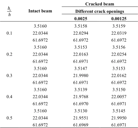
TABLE 9. Three first natural frequencies for CF, with different crack openings and depth and crack locationh=0.5.
c h
h Intact beam
Cracked beam Different crack openings 0.0025 0.00125
0.1
3.5160 3.5158 3.5159
22.0344 22.0294 22.0319
61.6972 61.6972 61.6972
0.2
3.5160 3.5153 3.5156
22.0344 22.0163 22.0254
61.6972 61.6971 61.6972
0.3
3.5160 3.5147 3.5153
22.0344 21.9980 22.0162
61.6972 61.6971 61.6972
0.4
3.5160 3.5139 3.5150
22.0344 21.9768 22.0057
61.6972 61.6970 61.6971
0.5
3.5160 3.5130 3.5145
22.0344 21.9551 21.9950
61.6972 61.6969 61.6971
As clear from obtained results, natural frequencies decrease with increasing crack depth and crack opening, and their values are less than intact beam.
9. CONCLUSION
be extended to structures with different shapes of cracks such as V or circular crack shapes that do not have analytical solutions.
10. REFERENCES
1. Dimarogonas, A.D., "Vibration of cracked structures: A state of the art review", Engineering fracture mechanics, Vol. 55, No. 5, (1996), 831-857.
2. Haisty, B. and Springer, W., "A general beam element for use in damage assessment of complex structures", Journal of
Vibration and Acoustics, Vol. 110, No. 3, (1988), 389-394.
3. Gounaris, G. and Dimarogonas, A., "A finite element of a cracked prismatic beam for structural analysis", Computers &
Structures, Vol. 28, No. 3, (1988), 309-313.
4. Ibrahim, F.K., "An elastoplastic cracked-beam finite element for structural analysis", Computers & Structures, Vol. 49, No. 6, (1993), 981-988.
5. Kirmser, P.G., "The effects of discontinuities on the natural frequency of beams, The College,(1945).
6. Dimarogonas, A.D., "Vibration engineering, West Publishing Company, (1976).
7. Christides, S. and Barr, A., "One-dimensional theory of cracked bernoulli-euler beams", International Journal of Mechanical
Sciences, Vol. 26, No. 11, (1984), 639-648.
8. Christides, S. and Barr, A., "Torsional vibration of cracked beams of non-circular cross-section", International Journal of
Mechanical Sciences, Vol. 28, No. 7, (1986), 473-490.
9. Reddy, J., "Energy and variational methods, John Wiley, New York, (1984).
10. Barr, A., "An extension of the hu-washizu variational principle in linear elasticity for dynamic problems", Journal of Applied
Mechanics, Vol. 33, No. 2, (1966), 465-465.
11. Shen, M.-H. and Chu, Y., "Vibrations of beams with a fatigue crack", Computers & Structures, Vol. 45, No. 1, (1992), 79-93. 12. Shen, M.-H. and Pierre, C., "Natural modes of bernoulli-euler
beams with symmetric cracks", Journal of sound and vibration, Vol. 138, No. 1, (1990), 115-134.
13. Shen, M.-H. and Pierre, C., "Free vibrations of beams with a single-edge crack", Journal of sound and vibration, Vol. 170, No. 2, (1994), 237-259.
14. Chondros, T. and Dimarogonas, A., "Vibration of a cracked cantilever beam", Journal of Vibration and Acoustics, Vol. 120, No. 3, (1998), 742-746.
15. Chondros, T., Dimarogonas, A. and Yao, J., "A continuous cracked beam vibration theory", Journal of sound and vibration, Vol. 215, No. 1, (1998), 17-34.
16. Chondros, T., Dimarogonas, A. and Yao, J., "Longitudinal vibration of a bar with a breathing crack", Engineering fracture
mechanics, Vol. 61, No. 5, (1998), 503-518.
17. Chondros, T., Dimarogonas, A. and Yao, J., "Longitudinal vibration of a continuous cracked bar", Engineering fracture
mechanics, Vol. 61, No. 5, (1998), 593-606.
18. Gudmundson, P., "Eigenfrequency changes of structures due to cracks, notches or other geometrical changes", Journal of the
Mechanics and Physics of Solids, Vol. 30, No. 5, (1982),
339-353.
19. Banks, H., Emeric, P. and Plancke, L., "Modeling of nonsymmetrical damage in plate-like structures", Mathematical
and Computer Modelling, Vol. 26, No. 3, (1997), 55-65.
20. Plakhtienko, N. and Yasinskii, S., "Resonance of second order in vibrations of a beam containing a transverse crack", Strength of
materials, Vol. 27, No. 3, (1995), 146-152.
21. Ballo, I., "Non-linear effects of vibration of a continuous transverse cracked slender shaft", Journal of sound and
vibration, Vol. 217, No. 2, (1998), 321-333.
22. Jassim, Z., Ali, N., Mustapha, F. and Abdul Jalil, N., "A review on the vibration analysis for a damage occurrence of a cantilever beam", Engineering Failure Analysis, Vol. 31, No., (2013), 442-461.
23. AL-Shudeifat, M.A., "On the finite element modeling of the asymmetric cracked rotor", Journal of sound and vibration, Vol. 332, No. 11, (2013), 2795-2807.
24. Gomes, H.M. and de Almeida, F.J.F., "An analytical dynamic model for single-cracked beams including bending, axial stiffness, rotational inertia, shear deformation and coupling effects", Applied Mathematical Modelling, Vol. 38, No. 3, (2014), 938-948.
25. Caddemi, S. and Morassi, A., "Multi-cracked euler–bernoulli beams: Mathematical modeling and exact solutions",
International Journal of Solids and Structures, Vol. 50, No. 6,
(2013), 944-956.
26. Dixit, A. and Hodges, D.H., "A general damage theory: Solution of nth-order equations using Unified Framework ", Mechanics
Research Communications, Vol. 38, No. 7, (2011), 486-493.
27. Rakideh, M., Dardel, M. and Pashaei, M., "Crack detection of timoshenko beams using vibration behavior and neural network", International Journal of Engineering-Transactions
C: Aspects, Vol. 26, No. 12, (2013), 1433.
28. Broek, D., "Elementary engineering fracture mechanics, Springer, (1986).
29. Ostachowicz, W. and Krawczuk, M., "Analysis of the effect of cracks on the natural frequencies of a cantilever beam", Journal
of sound and vibration, Vol. 150, No. 2, (1991), 191-201.
30. Rao, S.S., "Vibration of continuous systems, John Wiley & Sons, (2007).
31. Khaji, N., Shafiei, M. and Jalalpour, M., "Closed-form solutions for crack detection problem of timoshenko beams with various boundary conditions", International Journal of Mechanical
Sciences, Vol. 51, No. 9, (2009), 667-681.
32. Lin, H.-P., "Direct and inverse methods on free vibration analysis of simply supported beams with a crack", Engineering
A Simple Method for Modeling Open Cracked Beam
A. Nakhaei, M. Dardel, M. Ghasemi, M. Pashaei
Department of Mechanical Engineering, Babol Noshirvani University of Technology, Babol, Iran.
P A P E R I N F O
Paper history: Received 24 March 2014
Received in revised form 07 July 2014 Accepted 13 November 2014
Keywords:
Crack
Lumped Stiffness Model Step Beam
Natural Frequency Mode Shape
ﺪﯿﮑﭼ
ﮏﯾ لﺪﻣياﺮﺑهدﺎﺳشور ﺖﺳاهﺪﺷﻪﯾاراﺮﯿﺗﻞﮑﺷﻪﺑيﺎﻫرﺎﺘﺧﺎﺳردزﺎﺑكﺮﺗيزﺎﺳ
.
ﮏﯾترﻮﺻﻪﺑكﺮﺗشورﻦﯾارد
لﺪﻣﺮﯿﺗنﺎﻤﻟا ﯽﻣيزﺎﺳ
دﻮﺷ
.
ﻪﻠﭘﺮﯿﯿﻐﺗﺎﺑﺮﯿﺗﮏﯾترﻮﺻﻪﺑﺮﯿﺗورﻦﯾازا ﯽﻣﻪﺘﻓﺮﮔﺮﻈﻧردﻊﻄﻘﻣﺢﻄﺳرديا
ﻪﻟﺎﺴﻣو،دﻮﺷ
ﺨﺸﻣﻦﯾاﻞﺣترﻮﺻﻪﺑﺮﯿﺗﻞﮑﺷوﯽﻌﯿﺒﻃﺲﻧﺎﮐﺮﻓﻦﯿﯿﻌﺗ ﻪﺼ
ﻞﺣﻞﺑﺎﻗتوﺎﻔﺘﻣﻊﻄﻘﻣﺢﻄﺳولﻮﻃﺎﺑﺮﯿﺗﮏﯾياﺮﺑﺎﻫ
دﻮﺑﺪﻫاﻮﺧ
.
لﺪﻣﻪﺑ زﺎﯿﻧرﺎﮐﻦﯾاﺎﺑ فﺎﻄﻌﻧاﺎﺑﺮﯿﺗترﻮﺻﻪﺑﺮﯿﺗيزﺎﺳ
مﻮﻠﻋﺎﯾوﺖﺴﮑﺷيرﻮﺌﺗﻖﺒﻃﺮﺑﺰﮐﺮﻤﺘﻣيﺮﯾﺬﭘ
ﻞﯿﻠﺤﺗياﺮﺑﺮﻨﻓلﺪﻣﻦﯾازاهدﺎﻔﺘﺳاوكﺮﺗﯽﺘﻔﺳﻦﯿﯿﻌﺗياﺮﺑﻪﻃﻮﺑﺮﻣ دﻮﺑﺪﻫاﻮﺨﻧﻪﻃﻮﺑﺮﻣيﺪﻌﺑيﺎﻫ
.