FINITE ELEMENT SIMULATION OF
FLAT NOSE LOW VELOCITY IMPACT BEHAVIOUR OF
CARBON FIBRE COMPOSITE LAMINATES
A THESIS SUBMITTED TO
THE UNIVERSITY OF BOLTONIN PARTIAL FULFILLMENT OF THE REQUIREMENTS FOR
THE DEGREE OF DOCTOR OF PHILOSOPHY
BY UMAR FAROOQ
Umar Farooq ii In the Name of Allah: The Most Gracious, The Most Merciful-who showed the right path of righteousness and blessed me to get the strength to embark upon this task of peeping into the realms of facts and events. His blessings have always support and nurtured author’s goals and principles in life.
Umar Farooq iii Abstract
The work detailed in this thesis includes an extensive finite element simulation of low velocity impact behaviour of carbon fibre reinforced laminated composite panels subjected to flat and round nose impacts.
Carbon fibre composites are being widely used in aerospace structures due to their high strength and stiffness ratios to weight and potential to be tailored for structural components. However, wing and fuselage skins are vulnerable to foreign object impacts during manufacturing and service from tools maintenance tools and tool box drops. Such impacts particularly from flat nose tool drops inflict internal damages that are difficult to detect through routine inspections. The internal damage (barely visible) may cause severe degradation of material properties and reduction in compressive strength that might lead in unexpected catastrophic failures. Such failures result in loss of human lives and structural assets. That is a major concern for the aircraft industry. Most of the existing research is based on damage detection and control to improve integrity of structures so that an aircraft could reach nearest safe place to avoid failure after damage is detected.
It is very difficult to evaluate overall structural congruity and performance as structural degradation and damage progression occur after impacts. The impact is a dynamic event which causes concurrent loading and re-distributions of stresses once a ply fails or damage occurs. Most of the reported studies are based on physical experiments which are expensive, time consuming, and limited. The efficient way to predict performance evaluation of an impacted structural component is through integrated computer codes that couple composite mechanics with structural damage and failure progressions. Computational models can be very useful in simulating impact events, interpreting results, and making available the fast predictive tools for pre-design analysis and post-impact damage evaluations.
This investigation is primarily simulation based that integrates experimentally and numerically evaluated impact response of laminates manufactured by AircelleTM Safran Ltd
and HexcelTM Composites. Literature review and basic mathematical formulations relevant
Umar Farooq iv sixteen, and twenty four ply laminates subjected point, low, medium, and large nose impacts. The methodology used was based on previous experimental studies that assumed that impact damage provides the same stress concentration effect as crack, regions of degraded materials, or softer inclusions. The same assumptions were incorporated into simulation by inserting pre-assumed damage zones equivalent to impactors’ nose tips with within the volume of the laminates. Damage initiation, growth, and accumulation were investigated in terms of real scenarios with reference to the undamaged specimens. Several internal damage mechanisms were analysed via damage shift in multiple locations throughout the laminates’ volumes. The simulations can be useful to predict and correlate information on: existence, type, location, and extent of the damage in the impacted system to applied load. With this information and the loads applied to the system, measures can be proposed to reduce adverse effects of the impact induced damage.
The compressive residual strength after impact was predicted via buckling simulation models. The in-plane buckling analysis was implemented into PTC Creo SimulateTM. Effects
of the pre-assumed damage ply, damage zone, and coupled damaged-ply with damage zone were investigated via through-thickness re-locations. Critical buckling load and mode shapes were predicted with reference to the mid-surface of the laminates. Local buckling was simulated by introducing damage in a single ply adjacent to surface of the sub-laminate. Cases of pre-assumed delaminated ply from top to the mid-surface were simulated. Cases of mix-mode buckling analysis were simulated from coincident and combined effects of pseudo damaged ply as well as damage zones. The simulations predicted information can be useful to predict useful life remains (prognosis) of the damaged system. The information could also be useful to predict residual strength of similar cases at the beginning from material level, loading scenarios, damage progression to component and system level at various rates.
Umar Farooq v using explicit dynamic method. Two independent models were implemented in the software. The first model simulates displacement, velocity, and acceleration quantities. The second model computes in-plane stresses required to efficiently evaluate 3D stresses. The in-plane stress quantities were numerically integrated through-the-thickness utilising equilibrium to evaluate ply-by-ply through-thickness stresses. The evaluated stress values were then utilised in the formulation set of advanced failure criteria to predict damage progression and failure modes.
Simulation produced results were compared and verified against experiment produced data. Drop-weight impact tests were conducted to verify the selected simulation produced results. Non-destructive techniques and advanced data filtering algorithms available in MATLABTM were utilised to filter the noisy data and predict damage zone and load
threshold. The selected simulation results were compared against the experimental data, intra simulation results, and the results available in the literature and have to agree up to 90%.
Umar Farooq vi Acknowledgements
Completing a thesis such as this requires the understanding and assistance of a great many people. The author cannot hope to name all the individuals who have assisted him along the way but wishes to pay tributes to many people without whom this achievement would not have been possible.
The most importantly, the author owes his deepest gratitudes to Alightly Allah (SWT) for His continuous blessing throughout bumby journey of his life where dreams come true.
First of all sincere appreciations and gratitudes go to Prof Dr Peter Myler for his encouragement, valuable time, and ability to guide excellently throughout this endeavour. Moreover, for the person he is, his vision and knowledge are only surpassed by his generous personality. Those who have had the privilege of interacting with him will agree that he is a teacher and a fried. The author has had the privilege of working with such a highly reputed professor. Many thanks go to Prof Dr Baljinder K Kandola and Dr Gerard Edwards for being author’s co-supervisors and for their many fruitful and constructive comments during discussions and presentations.
The author particularly thanks to Mr Zubair Hanslot and Mr Karl Gregory for their excellent teaching of finite element analysis, computer aided design, and computational modelling courses. Particular thanks go to Miss Charly Slyter, Mr William Hales, Mr Sathish Kiran Nammi, and Mrs Sravanthi Nowpada for their help and assistance with working on commercial software in Design Studio. Special thanks go to Mr. Akbar Zarei of Centre for Material Research and Innovation for all the help and support with experimental work on INSTRONTM impact tester and Universal Material Testing machines.
Umar Farooq vii Mr Mushtaq Yaqubai along with his numerical analysis studentsat Hazara University Mansehra in Pakistan for their support during his service there.
The author will also remain grateful to numerous investigators and everyone who helped, supported, and contributed to the development of this body of knowledge.
The author would like to profoundly acknowledge The University of Bolton for providing him the study opportunity with excellent learning facilities. The author would also like to acknowledge and thank to HexcelTM Composites and AircelleTM Safran Limited for
donations of the carbon composite panels used in this research. Research interest on flat nose drop-weight impact behaviour of carbon composite panels by the staff from British Aerospace Engineering Systems, Salisbury, is greatly appreciated and acknowledged.
The author would like to acknowledge contributions of the faculty and staff of Composite Certification Laboratories of Manchester University and Electronic Department of Bolton University for their help with Ultrasonic C-scan and Eddy-Current testing of impacted panels. The author is thankful to Prof Dr John Milnes of the Fire Laboratory of Bolton University for his help with ignition loss testing to determining engineering properties of the panels. The author would also like to extend his gratitude’s to Mr Jason Bolton for his help with manufacturing purpose-built flat nose impactors and assistance with the workshop work.
Umar Farooq viii Table of Contents
Acknowledgements ... vi
List of Figures ... xv
List of Tables ... xxi
Chapter 1 Introduction ... 1
1.1. Introduction ... 1
1.2. Fibre reinforced laminated composites ... 1
1.3. Foreign object impacts of composites and internal damage ... 3
1.4 Statement of the problem ... 6
1.5 Methodologies to study low velocity impact on composites ... 6
1.5.1 Experimental methods and issues ... 6
1.5.2 Analytical methods and limitations ... 7
1.5.3 Computational modelling methods ... 8
1.6 Motivations and need for computational modelling ... 8
1.7 Selection of computational modelling methodology ... 9
1.8 Goals and objectives of the study ... 9
1.9 Contribution of the investigation ... 12
1.10 Organization of the thesis ... 13
Chapter 2 Literature review ... 16
2.1 Review ... 16
2.2 Fibre-reinforce composites and low velocity impact damage ... 16
2.3 Impact damage resistance of composite laminates ... 18
2.4 Impact damage tolerance of composite laminates ... 19
2.4.1 Global buckling analysis ... 19
2.4.2 Local buckling analysis... 20
2.4.3 Mixed mode buckling analysis ... 20
2.5 Properties determinations of composite laminates ... 21
2.6 Simulation of drop-weight low velocity impact of laminates ... 22
2.7 Low velocity impact testing of laminates and damage diagnostics ... 24
2.8 Data filtering and extrapolation of test generated data to predict damage ... 29
2.9 Summary ... 30
Umar Farooq ix
3.1 Review ... 32
3.2 Modelling impact of composite laminates ... 32
3.2.1 Static load-deformation ... 33
3.2.2 Impact dynamic analysis ... 36
3.3 Influence of impactor’s nose shape and loading area ... 37
3.4 Residual strength from buckling analysis ... 39
3.5 Selection of finite element simulation methodology ... 41
3.6 Summary ... 42
Chapter 4 Load-deflection simulation using PTC Creo SimulateTM software ... 43
4.1 Review ... 43
4.2 Laminates, impactor nose profiles, and material properties ... 43
4.2.1 Laminates and impactors ... 43
4.2.2 Material properties of undamaged and damaged laminates ... 44
4.3 Selection of methodology and software ... 46
4.3.1 The load-deflection methodology ... 46
4.3.2 The commercial software PTC Creo SimulateTM ... 47
4.4 Developing static load-deflection computational model ... 47
4.5 Static load-deflection predictions of undamaged laminates ... 49
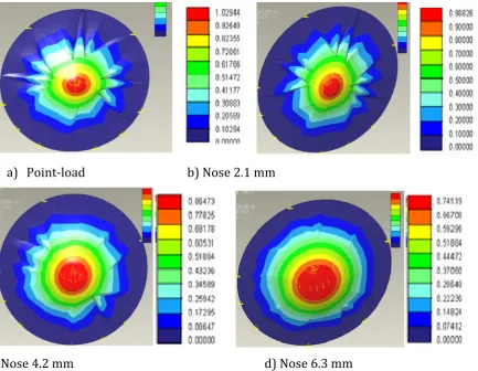
4.5.1 Approximation of damage shapes corresponding to impactor nose profiles ... 49
4.5.2 Comparison of simulated and experimental results ... 50
4.5.3 Comparison of simulated results for flat and round nose impactors ... 51
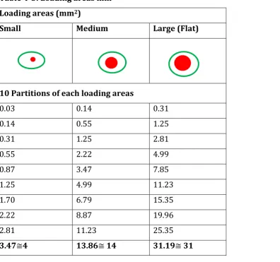
4.5.4 Influence of loading area influence to undamaged laminates ... 53
4.5.5 Influence of partitioned loading area to undamaged laminates ... 54
4.5.6 Selection of the pre-assumed damage methodology ... 56
4.6 Simulation of pre-assumed damage induced load-deflection ... 58
4.7 Discussion of the simulation generated results ... 60
4.7.1 Impactor nose shape against lay-up sequence ... 60
4.7.2 Influence of damage locations ... 63
4.7.3 Impactor nose on against successive damage zone and loading area ... 65
4.8 Impactor nose shape against through-thickness damage location ... 70
4.8.1 24-Ply laminate ... 70
4.8.2 16-Ply laminate ... 72
4.8.3 8-Ply laminate ... 74
Umar Farooq x
Chapter 5 Residual strength prediction using PTC Creo SimulateTM software ... 78
5.1 Review ... 78
5.2 Methodology for buckling analysis ... 78
5.2.1 Determination of buckling load of the sub-laminate ... 78
5.2.2 Determination of buckling load of laminated plate ... 81
5.3 Pre-assumed de-lamination induced buckling analysis ... 86
5.3.1 Finite element meshing schemes ... 87
5.3.2 Simulation of un-damaged laminate ... 92
5.3.3 Simulation of damaged laminate ... 93
5.4 Validation of selected buckling analysis methodology ... 95
5.4.1 Influence of pre-assumed de-laminated zone on buckling load ... 95
5.4.2 Influence of delamination depth (location) on buckling load ... 96
5.5 Comparison of intra-simulation results ... 98
5.5.1 Constant sized pre-assumed delaminated zone ... 98
5.5.2 Increasing pre-assumed damage zones ... 100
5.5.3 Symmetric and un-symmetric lay-ups ... 101
5.6 Numerical results and discussions ... 103
5.6.1 Global buckling analysis ... 103
5.6.1.1 Simulation of hole laminate ... 103
5.6.1.2 Damaged ply at various locations ... 105
5.6.2 Local buckling analysis... 108
5.6.2.1 Single pre-assumed damaged zone at various locations ... 109
5.6.2.2 Multiple pre-assumed damaged zone at various locations ... 112
5.6.2.3 Switching of local and global buckling modes ... 113
5.7 Mixed-mode buckling simulation ... 114
5.8 Summary ... 118
Chapter 6 Determination of physical and mechanical properties ... 120
6.1 Review ... 120
6.2 Determination of properties ... 120
6.3 Determination of physical properties ... 121
6.4 Determination of elastic properties of a lamina (Rule of Mixture) ... 122
6.5 Engineering constants for orthotropic lamina in 2D ... 126
6.6 Engineering constants in 3D ... 131
Umar Farooq xi
6.8 Determining elastic constants from flexure theory ... 138
6.9 Experimental methods to determine mechanical properties ... 140
6.9.1 Tensile test ... 141
6.9.2 Flexural test ... 143
6.9.2.1 Young’s modulus based on load-displacement measurements ... 146
6.9.2.2 Young’s modulus based on strain measurements ... 146
6.9.2.3 Young’s modulus based on slope measurements... 147
6.9.3 Hart Smith rule ... 148
6.9.4 Determining effective moduli for laminated composites... 149
6.10 Summary ... 152
Chapter 7 Simulation of drop-weight impact using ABAQUSTM software ... 154
7.1 Review ... 154
7.2 Theoretical aspects of the contact-impact for low velocity impact ... 154
7.3 Simplified modelling of impact problem using contact law ... 156
7.3.1 Implicit method ... 159
7.3.2 Explicit method ... 162
7.4 Materials and geometric properties of laminates and impactors ... 167
7.5 Experimental testing and computer simulation of drop-weight impacts ... 170
7.5.1 Impact test facility ... 170
7.5.2 Impact test procedure ... 173
7.6 Comparison of results for flat and round nose impactor ... 176
7.6.1 Experimental results of 8-Ply laminate at 1.7 m/s velocity ... 176
7.6.2 Comparison of damage evaluation through velocity parameter ... 177
7.6.3 Experimental and simulated results ... 177
7.6.4 Comparison of the results through delaminated zone ratios ... 178
7.7 Theoretical aspects of stress-based methodology ... 183
7.7.1 Determination of forces and moments at mid-plane ... 184
7.7.2 Effect of Poisson’s ratios on through-thickness stresses ... 186
7.7.3 Determination of through-thickness stresses ... 189
7.8 Failure theories for impacted composite laminates ... 191
7.8.1 Failure prediction using limits criteria ... 192
7.8.1.1 Maximum stress criteria (limit theory) ... 192
Umar Farooq xii
7.8.2 Interactive polynomial criteria ... 193
7.8.3 Mode base failure criteria ... 194
7.9 Material properties and plan of simulations using ABAQUSTM software ... 196
7.9.1 Simulation models with sweeping meshes ... 196
7.9.2 Adaptive meshing techniques ... 197
7.10 Discussion based on intra-simulation results ... 199
7.10.1 Impact of 8-Ply laminate ... 199
7.10.1.1 Impact velocity 1.7 m/s ... 199
7.10.1.2 Impact velocity 2.2 m/s ... 201
7.10.2 Impact of 16-Ply laminate... 204
7.10.3 Impact of 24-Ply laminate... 208
7.11 Summary ... 212
Chapter 8 Low velocity impact of composite laminates ... 214
8.1 Review ... 214
8.2 Carbon fibre reinforced laminates and type of impactors ... 214
8.3 Drop-weight impact test methodology... 214
8.3.1 Impact testing plan ... 215
8.4 Non-destructive damage detection techniques ... 216
8.4.1 Visual inspections ... 217
8.4.2 Eddy-current (electromagnetic induction) ... 218
8.4.3 Ultrasonic c-scans techniques ... 219
8.5 Comparison of results ... 220
8.5.1 Damage assessment of 8-Ply laminates ... 220
8.5.2 Damage assessment of 16-Plylaminates ... 224
8.5.3 Damage assessment of 24-Plylaminates ... 226
8.5.4 Prediction of impact induced damage area ... 228
8.5.5 Laminates of different material properties ... 231
8.5.5.1 8-Ply laminate impacted at velocity 1.7 m/s ... 231
8.5.5.2 16-Ply laminate impacted at velocity 3.12 m/s ... 231
8.5.5.3 24-Ply laminate impact energy: 20 J, 30 J, and 50 J ... 232
8.6 Limitations associated with testing and non-destructive techniques ... 233
8.7 Theoretical determination of impact parameters ... 234
Umar Farooq xiii
8.7.2 Parameters determined from impact test generated data ... 235
8.7.2.1 Forces, mass and acceleration ... 235
8.7.2.2 Energy balances (virtual work and d’Alembert’s principle) ... 236
8.7.2.3 Energy absorbed by target ... 237
8.7.2.4 Determination of contact duration ... 241
8.7.3 Comparison of load-deflection and drop-weight impact results ... 243
8.7.4 Parameters determined from quasi-static load testing ... 244
8.8 Delamination threshold load determine from facture mechanics ... 247
8.8.1 Threshold load of single delamination ... 248
8.8.2 Threshold load of multiple delaminations ... 252
8.9 Influence of impactor nose shape ... 253
8.9.1 Backface strain under point nose impact ... 253
8.9.2 Backface strain under flat nose impact ... 255
8.9.3 Critical threshold load under flat loading ... 258
8.9.4 Threshold load associated with ring loading ... 260
8.9.5 The second threshold load associated with back face cracking ... 261
8.10 Summary ... 263
Chapter 9 Analysis of test generated data ... 265
9.1 Review ... 265
9.2 Selection of data filtering and data extrapolation techniques ... 265
9.3 Data filtering based on built-in filters (data acquisition system) ... 268
9.3.1 8-Ply laminate impacted at different velocities ... 268
9.3.2 8-Ply laminate impacted from different nose profiles ... 268
9.3.3 Energy history for 8-Ply laminate ... 269
9.3.4 Comparison of load, displacement, velocity, and deflection history ... 270
9.3.5 Limitations of the built-in filters ... 271
9.4 Data filtering using statistical (moving average) methods ... 273
9.4.1 16-Ply laminate comparison of impact velocity and impactor nose ... 274
9.4.2 16-Ply laminate energy history ... 275
9.4.3 Comparison of load, displacement, velocity, and deflection history ... 276
9.4.4 Load and energy for different lay-ups ... 277
9.4.5 Higher order moving average methods ... 277
9.4.6 Limitations of the statistical (moving average) filters ... 278
Umar Farooq xiv
9.5.1 16-Ply and 24-Ply laminate prediction of energy ... 280
9.5.2 Comparison of load, displacement, velocity, and deflection history ... 284
9.5.3 16-Ply and 24-Ply laminates versus flat and round nose impactors ... 284
9.5.4 Limitations of the filters based on numerical techniques ... 285
9.6 Data filtering and extrapolation using Fast Fourier algorithms ... 285
9.6.1 Fast Fourier algorithms as filters ... 285
9.6.2 Energy history for 24-Ply laminate ... 290
9.6.3 16-Ply and 24-Ply laminates versus flat and round nose impactors ... 291
9.6.4 Comparison of load, displacement, velocity, and deflection history ... 293
9.6.5 Validation of the results obtained using Fast Fourier filters ... 297
9.6.5.1 Validation against available data ... 297
9.6.5.2 Validation of the results against statistical filter ... 298
9.6.5.3 Validation of the results against mean value filter... 299
9.7 Summary ... 300
Chapter 10 Conclusions and recommendations for future work ... 303
10.1 Review ... 303
10.2 Summary of each chapters’ conclusions ... 303
10.3 Major contribution of the investigations ... 306
10.3.1 Influence from flat nose shape impactors ... 307
10.3.2 Efficient prediction of through-thickness stresses and failure modes ... 307
10.3.3 Damage prediction through data filtering and data extrapolation ... 308
10.3.4 Recommendations for future investigations ... 308
Appendix: Selected publications ... 325
Appendix A Journals ... 325
Umar Farooq xv List of Figures
Figure 1-1: Superior properties: widely used in aircraft industry ... 2
Figure 1-2: Evolution of composite usage in aircraft structures [2] ... 3
Figure 1-3: Foreign object drop-weight impact threat ... 3
Figure 1-4: Schematic of low velocity impact and common damage modes [3] ... 4
Figure 1-5: Various failure modes at different scales [5]. ... 5
Figure 2-1: Micro-macro mechanical analysis model ... 17
Figure 2-2: Integration techniques function of strain-rate [129]. ... 25
Figure 2-3: Typical trapezoidal distribution of damage in laminates [133] ... 26
Figure 2-4: Frequency range for ultrasonic application [144] ... 28
Figure 3-1: General laminate symmetrical about its middle-plane ... 32
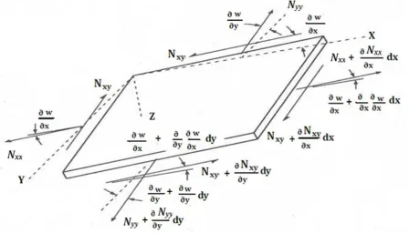
Figure 3-2: Forces and moments acting on a plate ... 33
Figure 3-3: Local and global axes of matrix and rotated fibres ... 36
Figure 3-4: Differential element positions for buckling analysis ... 40
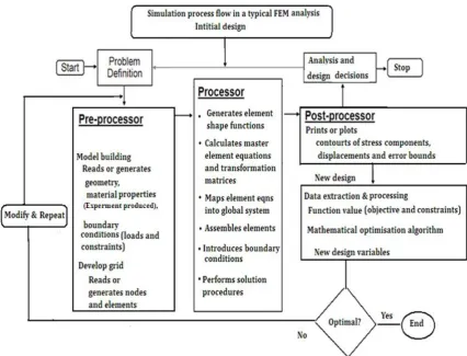
Figure 3-5: Common finite element simulation process of engineering problems. ... 42
Figure 4-1: Schematic of: a) fibre orientation, b) laminate, and c) circular cut-out ... 44
Figure 4-2: Schematic of impactor noses with nose diameters ... 44
Figure 4-3: A typical pre-processed meshed model for 24-Ply laminate ... 48
Figure 4-4: Typical computer generated damage resistance models ... 49
Figure 4-5: Photographs: a) front surface and b) close up image ... 49
Figure 4-6: C-scanned images of: a) 8-Ply, b) 16-Ply, and c) full size 24-Ply laminate .... 50
Figure 4-7: Comparison of 8-Ply laminate impacted by impact nose 2.1 mm. ... 51
Figure 4-8: Simulated contours of 8-Ply laminates: a) flat and b) round nose. ... 52
Figure 4-9: Simulated 8-Ply laminate: a) legend table and b) stress contours [4]. ... 52
Figure 4-10: Images show damage in red colour ... 53
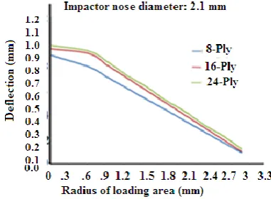
Figure 4-11: Deflection against radius of loading area ... 55
Figure 4-12: Deflection against radius of loading area ... 55
Figure 4-13: Deflection against radius of loading area ... 56
Figure 4-14: Overlapping zones a) single, b) two, and c) Three... 58
Figure 4-15: Static load-deflection analysis flowchart... 60
Figure 4-16: Deflection v location of damage ply for 8-Ply at nose 6.3 mm ... 64
Figure 4-17: Deflection v loading area for 8-Ply at nose 6.3 mm ... 64
Umar Farooq xvi
Figure 4-19: Deflection v loading area for 24-Ply laminate 3 noses ... 67
Figure 4-20: Deflection v loading area for 24-Ply laminate 3 noses ... 68
Figure 4-21: Deflection v loading area for 24-Ply laminate 3 noses ... 69
Figure 4-22: Deflection against damage location 24-Ply laminate v impactor nose ... 71
Figure 4-23: Deflection against damage location for16-Ply laminate v impactor nose ... 73
Figure 4-24: Deflection against damage location for8-Ply laminate v impactor nose .... 75
Figure 5-1: Schematic representation (1) sub-laminate and 2) column). ... 79
Figure 5-2: Bending and compression acting on a delaminated orthotropic plate: a) Theoretical, b) Local buckling, and c) Global buckling modes ... 82
Figure 5-3: Finite element model representation ... 88
Figure 5-4: Undamaged a) schematics and b) finite element model ... 90
Figure 5-5: a) Un-meshed, b) Course meshed, c) Mapped mesh, d) Fine meshed, and e) Loaded and fine meshed ... 92
Figure 5-6: Double delamination simulation at the mid-plane [1] ... 94
Figure 5-7: Single delamination simulation at the mid-plane [1] ... 94
Figure 5-8: Residual strength v damaged zone (a) and b) Simulated ... 96
Figure 5-9: Buckling load v through-thickness location (a) and b) Simulated) ... 97
Figure 5-10: Schematics of 8-, 16-, and 24-ply specimens... 99
Figure 5-11: Buckling load v location of de-laminated zone diameter (mm) ... 100
Figure 5-12: Buckling load v damage zone for 8-, 16- & 24-Ply laminate ... 100
Figure 5-13: Buckling load v damage zone ... 101
Figure 5-14: Buckling load v through-thickness location damage area ... 102
Figure 5-15: Flowchart for damage tolerance analysis... 103
Figure 5-16: Schematics of laminate embedded within a hole... 104
Figure 5-17: Increasing pre-assumed damage zone against buckling load KN ... 105
Figure 5-18: Schematic of; a) damage ply and b) ply location ... 105
Figure 5-19: Buckling load against damage location of ply in 8-Ply laminate ... 106
Figure 5-20: Buckling load against damage location of ply in 16-Ply laminate ... 107
Figure 5-21: Buckling load against damage location of ply in 24-Ply laminate ... 107
Figure 5-22: Symmetric 8-Ply laminate: a) hole and b) damage ... 108
Figure 5-23: Buckling load against pre-assumed damage diameter: 20 mm ... 109
Figure 5-24: Buckling load against pre-assumed damage diameter zone: 40 mm ... 110
Umar Farooq xvii
Figure 5-26: Buckling load against pre-assumed damage diameter: 80 mm ... 111
Figure 5-27: Buckling load against pre-assumed damage diameter: 100 mm ... 111
Figure 5-28: Case 1: Buckling load against multiple damage for 24-Ply laminate ... 112
Figure 5-29: Case 2: Buckling load against multiple damage for 24-Ply laminate ... 113
Figure 5-30: Local buckling turns to global buckling (damage location effect) ... 114
Figure 5-31: Schematics of mixed-mode buckling model ... 115
Figure 5-32: Buckling load against damage location for8-Ply laminate ... 116
Figure 5-33: Buckling load against damage location for16-Ply laminate ... 116
Figure 5-34: Buckling load against damage location for24-Ply laminate ... 117
Figure 6-1: Flowchart of determining physical and mechanical properties ... 121
Figure 6-2: Stresses in an isotropic lamina under a plane stress condition. ... 126
Figure 6-3: Orthotropic lamina in a plane stress ... 127
Figure 6-4: Coordinate systems referred to 3D transformation relations. ... 134
Figure 6-5: Schematic of pure flexure of beam ... 138
Figure 6-6: Schematic of beam laminates with cross-section ... 141
Figure 6-7: Photographs of: a) laminate and b) INSTRONTM machine ... 142
Figure 6-8: Schematics: a) laminate bending and b) cross-sectional area ... 144
Figure 6-9: a) Test laminate b) test chamber ... 145
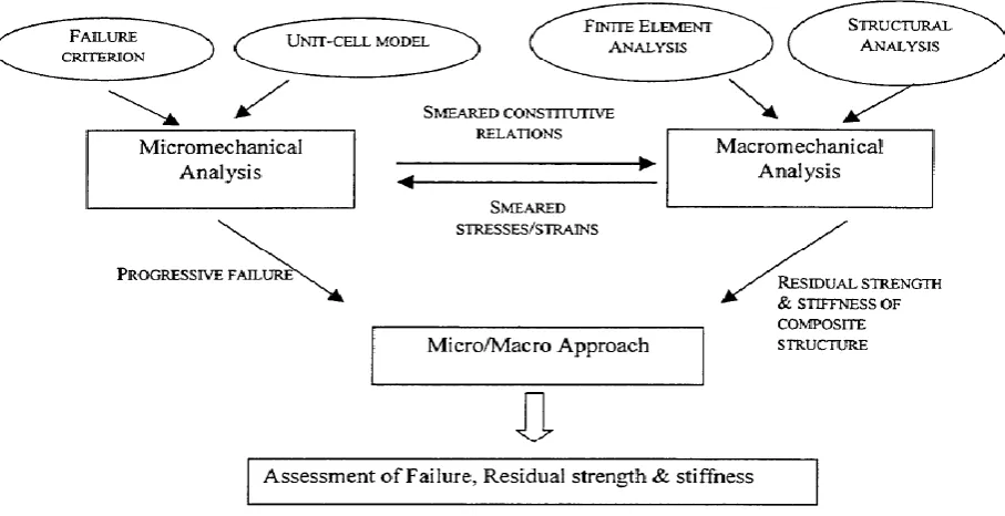
Figure 6-10: Progression of micro-macro analysis ... 151
Figure 7-1: Load-deflection response a) Static and b) Dynamic ... 155
Figure 7-2: Impactand local-global deformation ... 157
Figure 7-3: Time step and stress wave relationship ... 165
Figure 7-4: 8-Ply symmetric laminates ... 167
Figure 7-5: a) 8-ply, b) 16-ply, and c) 24-ply specimens ... 168
Figure 7-6: a) Schematic of a) specimen, b) cut-out of impact affected zone; c) round nose , and d) flat nose shape impactors ... 169
Figure 7-7: Flowchart of drop-weight impact analysis ... 170
Figure 7-8: INSTRONTM 9250HV impact test machine ... 173
Figure 7-9: Images of C-scanned 8-Ply laminates impacted at 1.7 m/s velocity ... 176
Figure 7-10: Comparison of 8-Ply laminates subjected to flat and round impactors [4]. ... 177
Figure 7-11: Comparison of 8-Ply laminates subjected to flat and round impactors. .... 178
Umar Farooq xviii
Figure 7-13: Selected C-Scan images and Eddy-current surfaces [4] ... 182
Figure 7-14: Comparison of 24-Ply laminate damage pattern [4] ... 183
Figure 7-15: Coordinate locations of ply in a laminate ... 185
Figure 7-16: Coordinate system and layer positions defined in a laminate ... 189
Figure 7-17: Computer generated meshed models and stack of 8-Ply laminate [4] ... 197
Figure 7-18: Computer generated impact models: a) Flat nose b) Round impactors .... 198
Figure 7-19: Top-ply in-plane stresses Pa of 8-Ply laminate at velocity 1.7 m/s [4]. .... 200
Figure 7-20: Failure index based on ply-by-ply through-thickness stresses ... 201
Figure 7-21: Top ply in-plane stresses (Pa) of 8-Ply laminate at velocity 2.2 m/s [4] ... 202
Figure 7-22: Failure index based on ply-by-ply through-thickness stresses ... 203
Figure 7-23: Failure index based on ply-by-ply through-thickness stresses ... 203
Figure 7-24: Top ply in-plane stresses Pa of 16-Ply laminate at velocity 3.12 m/s [4] . 205 Figure 7-25: Failure index based on ply-by-ply through-thickness stresses ... 206
Figure 7-26: Failure index based on ply-by-ply through-thickness stresses ... 207
Figure 7-27: Top ply in-plane stresses Pa of 24-Ply laminate at 3.12 m/s [4] ... 209
Figure 7-28: Top ply in-plane stresses Pa of 24-Ply laminate at velocity 4 m/s [4]... 210
Figure 7-29: Failure index based on ply-by-ply through-thickness stresses ... 211
Figure 7-30: Failure index based on ply-by-ply through-thickness stresses ... 211
Figure 8-1: Image of impacted laminate: a) front and b) back surfaces ... 217
Figure 8-2: Eddy current testing ... 218
Figure 8-3: Schematic of the ultrasonic equipment ... 219
Figure 8-4: C-scan images and Eddy-current surface ... 221
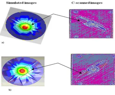
Figure 8-5: Simulated images and legend tables from ABAQUSTM software ... 222
Figure 8-6: C-scan images and Eddy-current surface ... 223
Figure 8-7: C-scan images and Eddy-current surface ... 224
Figure 8-8: C-scan images and Eddy-current surface ... 225
Figure 8-9: Simulated images and legend tables from ABAQUSTM software ... 226
Figure 8-10: C-scan images and Eddy-current surface ... 226
Figure 8-11: C-scan images and Eddy-current surface ... 227
Figure 8-12: Simulated images and legend tables from ABAQUSTM software ... 228
Figure 8-13: Comparison of 24-Plylaminate C-scan and Eddy-current images. ... 229
Figure 8-14: C-scan image of 8 J impact using the round impactor ... 232
Umar Farooq xix
Figure 8-16: Load-time history of flat and round nose impacts. ... 234
Figure 8-17: Static-indentation against drop-weight (filtered) at load 3.2 KN ... 243
Figure 8-18: Static-indentation against drop-weight (filtered) at load 8.9 KN ... 244
Figure 8-19: Load, energy and displacement hemispherical impact response. ... 245
Figure 8-20: Load, energy and displacement flat impact response. ... 246
Figure 8-21: Load, energy and displacement hemispherical impact response. ... 247
Figure 8-22: Delamination induced simply supported axis-symmetrical plate ... 248
Figure 8-23: Load-history of 8-Ply laminate under round nose impact scale... 249
Figure 8-24: Load, absorbed energy histories 34.5 J hemispherical impact [1]. ... 251
Figure 8-25: Nomenclature for exact and approximate solution ... 254
Figure 8-26: Schematic of 3-point beam bending of symmetric plate ... 254
Figure 8-27: Nomenclature for the integrated ring-loaded exact solution. ... 255
Figure 8-28: Clamped plate under variable load at radius rp (from 0 to a). ... 259
Figure 8-29: Clamped plate under ring/annular load ... 260
Figure 8-30: Clamped plate under central circular uniform load ... 262
Figure 9-1: Schematic of projected multiple damage onto a single plane ... 265
Figure 9-2: Schematic of possible damage modes [21]. ... 266
Figure 9-3: Flowchart depicting stages of present work... 267
Figure 9-4: Load-deflection response of 8-Ply laminates... 269
Figure 9-5: Energy-history plot of 8-Ply laminate round and flat nose impactors ... 269
Figure 9-6: a) Velocity, load and deflection histories; flat nose compared to b)... 270
Figure 9-7: a) Velocity, load and deflection history; round nose against b). ... 271
Figure 9-8: Load deflection comparison of 8-Ply laminate at velocity 1.7 m/s. ... 271
Figure 9-9: Load-deflection comparison of 8-Ply response at velocity 1.6 m/s ... 272
Figure 9-10: Load-deflection plot of 16-Ply laminate; round and flat impacts. ... 274
Figure 9-11: Load-deflection of 16-Ply laminate; round and flat nose impactors. ... 274
Figure 9-12: Energy-histories of 16-Ply laminate at velocity 3.12 m/s ... 275
Figure 9-13: Velocity, load and deflection of 16-Ply laminate; velocity 3.12 m/s. ... 276
Figure 9-14: Load, energy history of 16-Ply and 24-Ply laminate responses. ... 277
Figure 9-15: Load, energy history of 16-Ply response with high order filter. ... 278
Figure 9-16: Numerical filter and extrapolation relations... 279
Figure 9-17: Load, velocity and deflection of 24-Ply laminate at velocity 3.74 m/s. .... 284
Umar Farooq xx
Figure 9-19: Energy history of 24-Ply laminate impacted at velocity 3.74 m/s. ... 291
Figure 9-20: Load-deflection of 16-Ply at velocity 3.74 m/s ... 292
Figure 9-21: Load-deflection of 24-Ply laminate at velocity 3.74 m/s ... 292
Figure 9-22: Velocity, load and deflection of 24-Ply laminate; a) and b) round ... 293
Figure 9-23: Velocity, load and deflection of 24-Ply laminate; a) flat & b) round ... 294
Figure 9-24: Load-deflection plot of 24-Ply laminate filtered using Fast Fourier ... 296
Figure 9-25: Load-deflection plot of 24-Ply laminate filtered using Fast Fourier ... 296
Figure 9-26: Load-deflection threshold load 10 KN validates 8.9 KN. ... 298
Figure 9-27: Load-deflection plot validates predicted load 24 KN against 23 KN in ... 298
Figure 9-28: Load-deflection comparison to predict threshold loads ... 299
Umar Farooq xxi List of Tables
Table 4-1: Properties of laminate and impactor [1] ... 45
Table 4-2: Degraded material properties for pre-assumed damage zone ... 46
Table 4-3: Loading areas mm2... 54
Table 4-4: Schematics of damaged ply and damaged areas mm2 ... 57
Table 4-5: Approximation of net damage zones ... 58
Table 4-6: 8-Ply laminate simulated under impactor nose diameter 2.1 mm ... 61
Table 4-7: 8-Ply laminate simulated under impactor nose diameter 4.2 mm ... 62
Table 4-8: 8-Ply laminate simulated under impactor nose diameter 6.3 mm ... 63
Table 4-9: Top ply of 24-Ply laminate under impactor nose 6.3 mm ... 65
Table 4-10: Top-ply 24-Ply laminate under impactor nose 6.3 mm ... 67
Table 4-11: Top-ply 24-Ply laminate under impactor nose 6.3 mm ... 68
Table 4-12: Top-ply 24-Ply laminate under impactor nose 6.3 mm ... 69
Table 5-1: Ply-by-ply local buckling load KN ... 81
Table 5-2: Results of theoretical calculated buckling load ... 85
Table 5-3: Results of theoretical calculations based on Eq. (5-24) ... 86
Table 5-4: Ply-by-ply local buckling load (KN) ... 98
Table 6-1: Measured geometrical properties... 122
Table 6-2: Fibre contents of laminate of code Fibredux 914c-833-40. ... 122
Table 6-3: Beams lay-up configuration and geometrical dimensions ... 142
Table 6-4: Tensile test results ... 143
Table 6-5: Formulation used to calculate young’s modulus. ... 144
Table 6-6: Formulation used to calculate young’s modulus. ... 146
Table 6-7: Strain based calculated young’s modulus. ... 147
Table 6-8: Modulus based calculated young’s modulus. ... 147
Table 6-9: Young’s modulus for Fibredux 914C-833-40... 148
Table 6-10: Young’s modulus determined from Hart Smith Rule ... 149
Table 6-11: Number plies and their weight factors in a laminate ... 150
Table 6-12: Lay-up, angle, and modulus of 8-Ply laminate ... 150
Table 6-13: Comparison of Young’s moduli determined from various methods ... 151
Umar Farooq 1
Chapter 1
Introduction1.1. Introduction
This thesis reports computational and experimental investigation conducted on low velocity impact damage resistance and impact damage tolerance of carbon fibre composite laminates subjected to round and flat nose impacts. The work is a logical progression and extension of the work undertaken and compiled by James [1] which focused on the experimental data and testing fixture design. The thesis work shows qualitative agreement in the predicted and observed damage patterns and residual strength. While a great deal of efforts in the research areas have been directed towards the experimental characterizations, an efficient and accurate computational model for the prediction of impact damage behaviour of composites is still lacking. This is a consequence of the three dimensional nature of impact damage and complexity of the geometry of internal damage and delamination of composites. The work herein is aimed to develop an efficient computational model using finite element based software to efficiently handle the three-dimensional aspects that includes through-thickness stresses. The through-thickness stresses are then utilised in mode-based advanced failure criteria to predict matrix cracking and ply-by-ply delamination characteristics at ply interfaces.
1.2. Fibre reinforced laminated composites
Chapter 1 Introduction
Umar Farooq 2
Figure 1-1: Superior properties: widely used in aircraft industry
The composites are being widely used as structural elements in aerospace structures due to their high ratios of strength and stiffness to weight and flexibility features to tailor part integration and buckling resistance essential to structural stability. The heavier structural assemblies are being replaced by composites to enhance safety and saving in fuel consumptions. Market for the composites’ applications as structural element is constantly growing in aerospace, sport, automobile, civil and military applications. The BoeingTM 787
Dreamliner and AirbusTM 350 Extra Body Wide (XWB) and A380 are already utilising up to
Umar Farooq 3 Figure 1-2: Evolution of composite usage in aircraft structures [2]
1.3. Foreign object impacts of composites and internal damage
The composites offer great potential in characteristic flexibilities which make them more versatile in tailoring structural components. However, wings and fuselages are situated such that they are particularly exposed to maintenance tools (tool boxes) drops regarded as flat nose impact that inflicts internal damage as shown in Figure 1-3.
Figure 1-3: Foreign object drop-weight impact threat
Chapter 1 Introduction
Umar Farooq 4
internal damage mode initiates by intra-ply matrix cracking which grows and results in delamination that leads in fibre breakage as shown in Figure 1-4 with severe reduction in residual strength.
Figure 1-4: Schematic of low velocity impact and common damage modes [3]
Umar Farooq 5 stressed region may occur. As local damage on the microscopic level occurs in the form of fibre pull-out, matrix micro-cracking, fiber-matrix interfacial failure, matrix serrations and/or cleavage, and fiber breakage. On the macroscopic level, damage occurs via matrix cracking, delamination, and failures of individual plies. These localized damage mechanisms act to reduce damage (notch) sensitivity and increase the part strength. Brian Esp. reported some of the failure modes and their coupling in flowchart as shown in [5] Figure 1-5.
Figure 1-5: Various failure modes at different scales [5].
Chapter 1 Introduction
Umar Farooq 6
1.4 Statement of the problem
Accidental drop of low velocity and heavy mass tool or tool box on the aircraft wing and fuselage skin is common occurrence that cannot be avoided. Aircraft industry resorts to experimental analyses where components are being over designed to operate with significant impact damage. Analytical studies based on three-dimensional laminated plate theories are oversimplified that neglect contribution from through-thickness stresses. The round nosed impactors are mainly used to study impact on aircraft structure. However, a real impact is not likely to be from round nose shape. Impact from the flat nose shape impactor causes internal invisible damage under similar impact conditions that is a major concern for aircraft industry. Major concern is the inability to predict actual compressive residual strength from growth of internal damage. No standard experimental method exists to correlate impact load to the resulting damage and residual strength. Detailed investigations to study response of the composite laminates subjected to flat and round (for comparison) nose impactors are not reported in the available literature. Hence, computational model to characterise flat impact events that include contributions from through-thickness stresses to aid in prediction of damage formation and its effect on structural performance is required.
1.5 Methodologies to study low velocity impact on composites
Extensive experimental, analytical, computer simulations are underway to enhance inherit potential of composites in their applications and to minimise risks from the foreign object impact. Investigations are based on identifying common occurring damage scenarios and to concentrate on detection and elimination of damage without falling strength and stiffness of impacted components to unacceptable levels.
1.5.1 Experimental methods and issues
Umar Farooq 7 of physical equipment. At times, it is not feasible to test all vulnerable surfaces of an aircraft with increasing needs of on-line inspection and continuous assessment of aircraft’s health condition while in service. Standard test methods capable of predicting the remaining life of impact damaged structural element are not available. Moreover, existing mechanical tests are not always able to reproduce all the circumstances of environmental conditions, loadings, interactions, combinations and damage diagnostics that may encounter during an aircraft’s service life. Involvement of a large number of variables in the impact event, data scatting and variations in test result comparisons from one program to the others are also issues.
1.5.2 Analytical methods and limitations
Chapter 1 Introduction
Umar Farooq 8
1.5.3 Computational modelling methods
A large number of computational models have been developed based on the classical laminated plate theories. However, most of the studies are over simplified and based on three-dimensional solid elements that consume large computing resources. Major shortcomings of the existing analyses are neglecting of the through-thickness stresses that make failure and damage modes difficult to identify despite number of proposed failure criteria. Moreover, most of the existing studies use single scale mesh discretisation scheme over the entire domain for multi-layer structural element. This produces unnecessary excessive number of degrees of freedom mainly in the regions which are located at far distances from the impact zone where there is no need for such high level of details and resolution with fine scale meshing. Such discretisation processes result in large computation time and over-burdening of the available computing resources. The impact event is generally a local phenomenon that requires a fine-scale meshing of the high stress gradient regions within the computational domain to capture material and geometrical nonlinear effects. While the regions located outside of the impact vicinity do not go through such nonlinear effects mesh refinement and a relatively coarse mesh can be adopted.
1.6 Motivations and need for computational modelling
Umar Farooq 9 problems using computer simulations. The verification tests are being conducted at the end of the design processes. The huge computing power integrated with data and signal processing techniques and state-of-the-art software can be utilised to develop an efficient and reliable simulation model. The computing aids are also very useful in interpreting and comparing results. It thus becomes important to develop a computational model that could predict flat nose low velocity impact response of composites relatively efficiently for pre-design analysis.
1.7 Selection of computational modelling methodology
Simulation models based on PTC Creo SimulateTM and ABAQUSTM finite element software
were developed. The software codes are capable to discretise the computational domain with nonlinear effects. Moreover, the explicit codes in ABAQUSTM are generally employed
for numerical solution of impact problems due to their dynamic and highly nonlinear nature. The built-in features of the software options have the potential to serve and can be utilized with various levels of complexity and mechanical responses to independently mesh the sub-domains. The computational models can be very useful for a viable virtual design capability that allows parametric studies for validating the numerical results. The generated data could be useful for material selection purposes and possibly to make a pre-design (approximate) proposal of the impact performance of similar structural components with enhanced confidence in damage tolerance capabilities. The model can be modified to generate data from simulation of simple scenarios of operational structural components for comparison against experimentally recorded data.
1.8 Goals and objectives of the study
Motivated by the above statements six main goals were set to accomplish the investigations:
(a) To search and select literature regarding solution methods to the low velocity impact of composites
(b) Develop static load-deflection and buckling analysis models utilising PTC Creo SimulateTM software to validate selected results from the available quasi-static and
Chapter 1 Introduction
Umar Farooq 10
(c) Perform extended pre-assumed damage/delaminated zone simulations predicting ply-by-ply static load-deflection and buckling analyses.
(d) To determine and verify properties of carbon fibre laminates used in the analysis (e) To implement the drop-weight impact event by flat and round nose impactors in ABAQUSTM software using efficient meshing schemes to simulate load-deflection model
to predict elastic failure
(f) To develop stress based model to predict in-plane stresses to numerically integrate the 2D stresses via equilibrium equations to predict 3D stresses and to use them in advanced failure theories
(g) To conduct drop-weight experimental testing and predicting damage and delamination prediction using non-destructive techniques data interpretation and extraction techniques.
To achieve the goals, the objectives given below were set to:
(1) Develop static load-deflection finite element models to generate and correlate data to the pre-assumed damage zones against deflection. Cases of damage locations and sizes need to be simulated for:
a)Eight, sixteen, and twenty-four ply laminates
b)Pre-assumed damage corresponding to point, small, medium, and large impactor nose shapes
c) Relocations of the pre-assumed damage within volumes of laminates
d)Investigations of loading effects by partitioning loading areas under impactor nose profiles
e)Develop buckling analysis model to capture compressive residual strength after impact. The simulations need to be carried out for:
i) Local buckling analysis ii) Global buckling analysis.
iii) Mixed mode buckling analysis.
(2) Design and conduct property characterisation experiments to verify laminates properties used in the investigations. To determine and verify properties of carbon fibre laminates used in the analysis:
a) Physical properties from ignition loss tests
Umar Farooq 11 c) Rule of mixture and Hart Smith rule
d)Micro-mechanics and mechanics of composites formulations (3) Develop an independent model to predict load-deflection from flat and round nose
impacts to capture the dynamic effects of an impact load for: a) To simulate load-deflection model
b) To simulate stress based model to predict in-plane stresses
c) To determine through-thickness (3D) stresses utilising the computed in-plane (2D) stresses by numerical integrating equilibrium equations through-thickness
d) To predict ply-by-ply failure utilising the in-plane and through-thickness stresses in advanced failure criteria.
(4) Design and conduct drop-weight impact experiments on composite laminates to predict damage using non-destructive techniques for:
a) Damage and delamination prediction using non-destructive techniques and impact parameters using theoretical formulations b) Interpretation and extraction of damage and load drops (threshold
load) using data filtering and data extrapolation of test generated data
c) Comparisons and validation of drop-weight simulation generated and quasi-static results
(5) Draw conclusions regarding the validity of investigated results and techniques commonly used in the literature. Provide outcome of the integrated simulation analysis supported by experimental and analytical results consisting of the flat nose impact response of the composite laminates.
Chapter 1 Introduction
Umar Farooq 12
1.9 Contribution of the investigation
This investigation contributes in efforts towards efficient and reliable design analysis of the flat nose impact damage resistant and damage tolerant of composites. Capabilities of capturing internal damage and degradation via simulation significantly contribute in economic and performance benefits in the following aspects:
(1)To efficiently predict flat nose impact induced through-thickness stresses from two-dimensional simulations and utilise them to predict mode based failures. Through-thickness ply-by-ply failures, damage modes, and damage mechanisms occur in service life of an aircraft can be predicted efficiently. The simulation produced results can be useful to evaluate and provide resistance ability to a structural part at pre-design stage.
(2) Simulation predicts and measures sufficient static strength using pre-assumed embedded damage zones correlation to deflection quantities. The information can be useful to correlate damage detecting abilities and resistance to potential impact damage threats. Predicts damage resistance of components to maintain statistical design strength by correlating against undamaged (as is) components.
(3)To predict residual strength of laminate embedded with possible damaged and delaminated zones. Such predictions correlate ability of the laminates at pre-design stage to tolerate presence of the anticipated damage and possess adequate structural integrity. Simulations can be useful in predicting damage tolerance capabilities without physical testing of many components under ultimate loads. (4)Physical and mechanical properties determined from tests can be augmented with
relevant calculations and formulations to determine enhanced using micro-macro mechanics laws.
Umar Farooq 13
1.10 Organization of the thesis
The thesis is structured in ten chapters corresponding to the progression of the research. The chapters are organized as follows:
Chapter I introduce investigation topic, motivation, primary aim and objectives, and contributions of the investigations, and indicate organization of the thesis.
Chapter II provides a literature review in the relevant aspects of laminated composites impacted from various impactor nose profiles with information on references.
Chapter III outlines relevant theory associated with the impact of composite plates applicable to this research: load-deflection, drop-weight impact, buckling analyses and failure theories.
Chapter IV deals with the simulation model developed on the basis of load-deflection methodology in “PTC Creo SimulateTM” software. Various test cases of pre-assumed
ply-by-ply damage laminates, impactor nose profiles, and stacking sequences were investigated. Pre-assumed damage zones were correlated to simulation produced deflection quantities. Selected results were compared to the available experimental results.
Chapter V consists of simulation of compressive-bending buckling analysis to predict residual strength of the damaged laminates. Independent models were developed for local, global, and mixed-mode buckling analyses. Simulations produced buckling load quantities were correlated to ply-by-ply location of the delaminated zones and damaged ply from the top ply to the middle-surface ply are presented. Aspects of the interaction between various buckling modes correlated to critical buckling load to establish correlation between residual strength and the de-laminated zones. Comparisons of selected results with the available results in the literature are also presented.
Chapter 1 Introduction
Umar Farooq 14
determine the properties from micro-macro mechanics and mechanics relations have also been reported.
Chapter VII is concerned with drop-weight test incorporated into commercial software ABAQUSMT explicit dynamic routine. This was then bench marked against experimental
work to make available possibly the reliable and fast predictive method that efficiently determines through-thickness stresses and utilises them to predict ply-by-ply failure. Main focus of the explicit analysis was effects from flat nose shape impactors as experimental results were available for this type of impactor.
Chapter VIII is concerned with the physical drop-weight experimental impact tests carried out for round and flat nose shape impactors on eight, sixteen, and twenty-four ply laminates of different thicknesses. Non-destructive damage evaluation techniques (visual, ultrasonic, and eddy-current) were utilised to visualize and quantify the extent of the internal damage. In addition, details of selected results comparison and validation against analytically determined parameters from quasi-static methodology are reported. Mathematical formulation to determine unknown parameter from known parameters without further testing are described.
Chapter IX is concerned with the analysis of data generated from drop-weight experimental impact tests carried out for round and flat nose shape impactors on eight, sixteen, and twenty-four ply laminates of different thicknesses. Moreover, it reports filtering and extrapolation techniques of clipped data utilised to extract more useful information about impact damage through fluctuations in load-deflection curves. Comparisons of selected plots carried out against the results available in literature and to the intra-simulation computational results.
Chapter 2 Literature review
Umar Farooq 16
Chapter 2
Literature review2.1 Review
This chapter reviews published work found relevant to the research program presented in this thesis. Underlying theme of the review relates flat nose low velocity impact performance of carbon fibre-reinforced composite laminates. Contributions from experimental, analytical, and numerical analyses were reviewed. Selected aspects of: load-deflection, residual strength, physical testing of laminates’ properties, drop-weight impact simulation and testing, dynamic of impact, through-thickness stresses, and failure theories were reviewed. Moreover, nondestructive damage detection techniques, determination of impact parameters, data filtering and extrapolation techniques were also reviewed.
2.2 Fibre-reinforce composites and low velocity impact damage
Umar Farooq 17 Figure 2-1: Micro-macro mechanical analysis model
The flat nose low velocity impact does not result in total penetration rather induces matrix cracking, delamination and fibre breakage [8], [9] and [10]. The impact velocities remain below 20 m/s [11] and [12]. The first damage generally occurs in the form of matrix cracking while stress variations through-thickness results in back-face cracking [13]. In the vicinity of the impact location high concentrations of stresses create through-thickness matrix micro-cracks in the shape of a pine tree [14] and [15]. Second types of matrix cracking, pairs of inclined cracks, emanating from the impact location in a radial pattern are reported in [16]. The matrix cracks appear in the upper and middle layers and shear cracks were inclined at 450, starting under the impactor edges due to high shear stresses related to
Chapter 2 Literature review
Umar Farooq 18
top for thick laminate [20].The intertwine internal damage-delamination mechanisms make impact analysis complicated. However, many of the load drops and energy absorbing mechanisms can be negligible in their contributions to simplify and group number of categories and zones to associate failure modes in load-time history plots [21] and [22]. Delaminations are always accompanied by matrix cracks and, in laminates made from unidirectional plies at the interface between two plies [23], [24] and [25]. Moreover, delaminations are oriented in the fibre direction in plies with their major axis parallel to the fibre direction of the lower ply at the interfaces [26] and [27]. Experimental and finite element analysis report the delamination as the pre-dominate fracture mode II neglecting the mode I fracture to simplify the analysis [28]. Cantwell [29] and [30] separated the impact event into damage resistance and damage tolerance categories to study one event at a time:
(a) Impact damage resistance (measured by ability to resist impact damage to occur) can be analysed as static-load deflection and drop-weight impacts.
(b) Impact damage tolerance (measured by compression after impact testing: buckling load) means that the structural components must withstand low velocity impact over the lifetime without loss of structural integrity.
2.3 Impact damage resistance of composite laminates
Umar Farooq 19
2.4 Impact damage tolerance of composite laminates
Damage tolerance from damage and delamination induced buckling analysis is an important failure mechanism of composites [41] and [42]. A review of damage tolerant analysis of laminated composites is presented [43]. Fan reported in [44] and [45] that tensile strength is about twice the compressive strength that compressive strength has become the accepted standard as a critical design measure for residual strength of a damaged part in aircraft industry. Thin laminates may buckle at local, global or mixed (both) levels under excessive loading [46]. The buckled component cannot resist any additional load as buckle/critical load is considered the failure load. Ghasemi in [46] and Hu in [47] have shown strong correlation between size of the delaminated zone and the residual compressive strength. They predicted that the smaller damage areas give smaller reductions in residual strength. Hull in [48] identified that buckling load and the subsequent post-buckling modes of the delaminated region are a critical factor buckling analysis. Hull et al in [47] also proposed three stages of the anticipated/possible range of delamination zones. Size of the delaminated zone could be estimated by strength ratio of the undamaged laminate.
2.4.1 Global buckling analysis
Chapter 2 Literature review
Umar Farooq 20
2.4.2 Local buckling analysis
If a component has a region where the relative thickness to depth ratio is less than 10% [52] the possibility of “local buckling” may be considered. It is a rare occurrence, but when it does occur the results can be sudden and catastrophic. The fundamental assumption in local buckling analysis is that only a sub-laminate near the free surface undergoes deformation and the rest of the laminate remains unperturbed. Laminates of the un-symmetric lay-ups induced with delaminated locally buckle at loads lower than those needed to achieve global buckling. Presence of delaminations in any laminated structure results in the development of bounding regions which are dictated by the area in through-thickness position and near the free surface [53] and [54]. The local buckling of composite laminar plates with various delaminated shapes is reported in [55]. Under in-plane compressive loading, local instability (delamination buckling) may arise, capable of sustaining higher loading conditions in a post-buckling mode that could promote delamination growth [56]. The locally buckled laminates produced high local stresses at the delamination fronts that accelerate growth of delaminations that further decreases strength of the laminates [57]. Single-mode local buckling demonstrated that two mechanisms govern the post-buckling state; the closing process and the opening process [55]. The first implicates the post-buckling mechanism, where the mid-points of the sub-laminates move in the same direction, but are separated from each other, contrary to the second where they move in opposite directions. That is, when the delaminated layer has buckled locally. The initial out-of-plane deflection results in the formation of a natural bending moment. The closing process is the immediate post-buckling mechanism [59] and [60].
2.4.3 Mixed mode buckling analysis
Umar Farooq 21 [65]. Olsson R et al [66] performed experiments and analysis of laminates with artificial damage. Numerical and experimental studies established dependencies of the critical buckling load where lowest critical load is always related to the local mode [67]. The pre-assumed delaminations (introduce into the model or test) laminate with known positions, sizes and shapes have been employed regularly in experimental studies in order to investigate such mechanisms and interactions in a controlled environment [68]. Moreover, the delamination in-plane profile can be described by two basic geometric attributes [69] and [58] the delamination diameter (size) and delamination area. A strong correlation between delaminated area sizes to the residual compressive strength; smaller damage areas give smaller reductions in residual strength [70] and [71]. Approaches to describe the influence of impact damage on residual strength to apply the theory for notch failure and represent the impact zone by a soft inclusion are given in [72], [73] and [74]. The combination of the inclusion’s size and stiffness produces a unique stress concentration that may be used to predict the loss of strength reported in [75] and [76]. References [63], [77] and [78] reported damage induced buckling experimental analysis with artificial inclusion. Relationship between delamination and buckling load with artificial delamination zones is also reported in [79], [80]. Progressive failure algorithms to model non-linear behaviour and to capture compressive response of laminate are reported in [81] and [82]. Yazic [69] also studied the influence of square cut-out upon the buckling stability of multilayered composite plates using numerical and experimental methods. Baker in [70] and Besant [83] investigated damage tolerance optimization of stiffener induced laminated plates.
2.5 Determination of physical and mechanical properties of composites
Chapter 2 Literature review
Umar Farooq 22
lengths are reported in [92]. Investigation of deterring tensile properties of fibre reinforced angle ply laminated composites is given in [93] and [94]. Prediction of elastic properties of composite laminates for longitudinal loading is presented in [95] and [96]. Investigation of tensile properties of fibre reinforced angle ply laminated composites was conducted in [97], [98] and [99]. Tensile and thermo-mechanical properties of short carbon fibre reinforced composites were determined in [100], [101] and [102]. Flexural behaviour of reinforced concrete beams strengthened with pre-stressed carbon composites and shear properties of a carbon/carbon composite with non-woven felt and continuous fibre reinforcement layers are reported in [103], [104] and [105].
2.6 Simulation of drop-weight low velocity impact of laminates
Analytical and numerical models were suggested for prediction of impact damage initiation and growth during quasi-static response. Nyman et al [67] predicted the progressive failure in composite laminated laminates. Delfosse [72] compared impacts on fibrous composites by hemispherical shaped impactors that had the same incident energy over a range of velocities for conical, hemispherical and blunt nosed projectiles. It was shown that geometry of the projectile shape has considerable influence over the impact event in [71] and [72]. Mitrevski [73] investigated influence of four impactor nose profiles on the damage to composite laminates. He reported that the most extensive delamination damage was caused by blunt hemispherical impactor. Fawaz et al [74] numerically investigated performance of composites subjected to normal and oblique impacts using LS-DYNATM
Umar Farooq 23 shear stresses that develop cracks within plies. Impact on pre-stressed laminates under using the finite element method was investigated via Newmark time integration algorithm in [77]. The direct mode determining failure criteria are possibly the most useful of the four categories reported in [77]. Experimental and numerical investigations of low velocity impact on laminated composites were carried out in [79] and [82]. Low velocity impact of composite plate was investigated using finite element based software in [80], [81] and [82]. Besant et al [83] studied finite element modelling of low velocity impact of composite laminates. Drop-weight impact testing models were created in ABAQUSTM on-linear finite
Chapter 2 Literature review
Umar Farooq 24
2.7 Low velocity impact testing of laminates and damage diagnostics
Umar Farooq 25 Figure 2-2: Integration techniques function of strain-rate [129].
Chapter 2 Literature review
Umar Farooq 26
Figure 2-3: Typical trapezoidal distribution of damage in laminates [133]
Chapter 2 Literature review
Umar Farooq 28
Figure 2-4: Frequency range for ultrasonic application [144]
Common applications involve signal processing to estimate those phenomena strictly connected with damage presence like: signal attenuation, scattering, time of flight diffraction (TODF) and so on. However, the conventional C-scan technique is only able to highlight the projected delamination area. Improvements in the techniques have allowed one to measure the damage area on a ply-by-ply basis provided by the amplitudes of the echoes resulting from the inter-laminar surfaces. Such echoes are measured in order to observe the heli-coidal pattern of delaminations through the thickness of the laminate. Other ultrasonic techniques have also been used: for example backscattering appears to be capable of resolving inter-ply delaminations, matrix cracks in each ply and wavy and misaligned fibres [144] and [145]. When the delaminations are closely spaced and it is therefore difficult to discern each of them using ultrasonic methods, a comparison between optical micrographs, thermally-deployed layers and C-Scan records has been carried out [146]. It has recently been demonstrated that Eddy currents methods could be used for the inspection of composite materials [147] and [148]. Previous work on the use of eddy current techniques for composites testing have shown that fibre damage with or without matrix cracking can be detected and variations is successfully revealed [149]. However, the literature searched revealed that most of the non-destructive studies can only provide two-dimensional information on the damage pattern.
Umar Farooq

![Figure 1-2: Evolution of composite usage in aircraft structures [2]](https://thumb-us.123doks.com/thumbv2/123dok_us/98429.2011468/26.595.76.359.444.654/figure-evolution-of-composite-usage-in-aircraft-structures.webp)