22
Volume-4, Issue-1, February-2014,
ISSN No.: 2250-0758
International Journal of Engineering and Management Research
Available at:
Page Number: 22-26
A Review on Effect of Process Parameters on Weld Bead for GTAW
Parthiv T. Trivedi1, Ashwin P. Bhabhor2 1,2
Department of Mechanical Engineering, KSV University, Gandhinagar, INDIA
ABSTRACT
Among all the welding processes, the chief advantages in using Gas Tungsten arc welding (GTAW) for surfacing are high reliability, all position capability, ease of use, low cost and high productivity. With the growing emphasis on the use of automated and robotic system GTAW welding, with its all position capabilities, has been employed increasingly in mechanized surfacing in industry. It is reported that the strength of a welded joint is largely determined by the dimensions and shape of its bead. The profile of the bead has significant influence on the welding. From the cross-sectional area of the bead, the cooling rate of the weldment can be judged. Bead cross-sectional area along with the bead height (BH) and width determines the residual stresses and thus, distortion of the welded structure. Weld cracking is also related to the profile of the bead. Moreover, a considerable amount of micro-structural change occurs in the welded zone. The size of the grains in the welded zone is generally found to be larger than that of the base metal. Due to the above reasons, the mechanical properties of welded structure are dependent on the size and shape of the weldment. The effect of process parameters such as arc voltage, welding speed, welding current, type of shielding gas, shielding gas flow rate are considered in this review paper for GTAW.
Keywords: GTAW, Process Parameters, Arc voltage,
Welding speed, Welding current, Type of shielding gas, Shielding gas flow rate
.
I.
INTRODUCTION
The American Welding Society (AWS) defines weld as “A localized coalescence of metals or non-metals produced either by heating the materials to suitable temperatures, with or without application of pressure, or by pressure alone, and with or without the use of filler material.”
Indian Standard IS : 812-1957 defines the weld as “a union between two pieces of a metal at faces rendered plastic or liquid by heat or by pressure, or both. Filler metal may be used to effect the union”
International Organization for Standards (ISO) defines welding as “An operation by which two or more
parts are united, by means of heat or pressure, or both, in such a way that there is continuity of the nature of the material between these parts. A filler material, the melting between these parts. A filler material, the melting temperature of which is of the same order as that of the parent material, may or may not be used.”
TIG, is an acronym for “Tungsten Inert Gas” welding. TIG is a commonly used and accepted slag term. The proper terminology is “Gas Tungsten Arc Welding” or GTAW. This is the term used by welding engineers on blueprints, and in welding procedures.
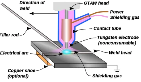
Gas tungsten arc welding, GTAW, uses a non consumable electrode to produce the weld. Weld area is protected from atmospheric contamination by a shielding gas (usually inert gas such as argon) and a filler material is normally used.
Fig. 1 TIG welding process illustration
23
II.
LITERATURE REVIEW
Mohd. Shoeb, Prof. Mohd. Parvez and Prof. Pratibha Kumari studied the various welding parameters such as welding speed, voltage and gas flow rate on HSLA steel.The effects of these parameters on weld bead geometry such as penetration, width & height have been studied. MIG welding was carried out on DC electrode (welding wire) positive polarity (DCEP). However DCEN in used (for higher burn off rate) with certain self- shielding and gas shield cored wires. Mathematical equations have been developed using factorial technique and the result of various effects are indicated[1]
Optimization was done to find optimum welding conditions to maximize tensile strength and percent
elongation of welded specimen. Confirmation tests were also conducted to validate the optimum parameter settings
Tensile Testing
The ultimate tensile strength of the machined specimen were tested in the calibrated universal tensile testing machine. Percent elongation was also calculated. Tensile test carried out according to ASTM standards, using specimen prepared as shown in figure 2.
Analysis of variance
Analysis of variance (ANOVA) is similar to regression in that it is used to investigate and model the relationship between a response variable and one or more independent variables. In this study general linear model is used to determine the influence of welding speed, current and gas flow rate on ultimate tensile strength and % Elongation.
.
Effect of arc voltage on weld bead geometry :
As arc voltage increases penetration increases gradually with increase in arc voltage and reaches a maximum value. The height decreases with increase in voltage but the reverse is true with the width and dilution. Increasing the arc voltage makes the bead wider, the height is reduced because the same volume of weld metal is involved. Greatest effect of individual parameter on bead width was of arc voltage. The increase in arc voltage resulted in the increase in bead width from 4.26 to 6.18mm. This increase in bead width could be attributed to the increased arc length with rise in arc, which resulted in large spread of the arc at its base and hence increased weld width. The increase in arc voltage also results in hotter arc, which means high fluid state of the deposited metal.
Effect of welding speed : It is not showing significant effect on penetration but at any current, bead width is inversely proportional to the welding speed . With high welding speed, the excess weld metal builds up due to rapid cooling of the weld pool edges and results in increase of height and simultaneously width decreases. Decrease in height could be due to the fact that weld pool size is affected by cooling rate, which decreases with increasing the welding current or by decreasing the travel speed. Thus at higher welding speed, size of the weld pool and metal deposition rate will decrease i.e. width, and height will decrease.
Effect of gas flow rate : It shows no significant effect on penetration but bead height is increasing, which may be due to the reason that the increased flow rate is providing space to in to increase. As the velocity of gas is increasing it is imparting low pressure on the bead, resulting in increase of height.
Palani P.K, Saju. M applied Response Surface Methodology was used to conduct the experiments. The parameters selected for controlling the process are welding speed, current and gas flow rate. Strength of welded joints were tested by a UTM. Percent elongation was also calculated to evaluate the ductility of the welded joint. From the results of the experiments, mathematical models have been developed to study the effect of process parameters on tensile strength and percent elongation[5].
Fig. 2 Dimensions of tensile test specimen
Optimization of process parameters
One of the most important aims of experiments related to welding is to achieve high value of tensile strength and Elongation. The response surface optimization is a technique for determining best welding parameter combination. Here the goal was to maximize UTS and % Elongation.
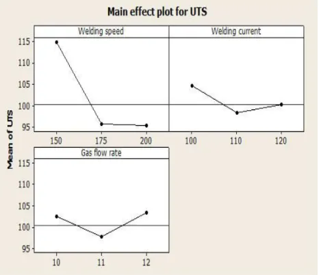
Effect of process parameters on UTS
The main effects of the plot, for UTS with the process parameter of welding speed, current and gas flow rate were shown in Fig.7.
24
Graph shows that UTS decreases from 115 MPato 95 MPa. when welding speed increases from 150mm/min to 200 mm/min,because of less penetration depth. UTS decreases from 105 MPa to 101 MPa when current changes from 100 Amps to 120 Amps, due to the result of increased input heat associated with the use of higher current. As gas flow rate changes from 10 LPM to 12 LPM,UTS increases from 103 MPa to 104 MPa,due to decrease in the porosity level of weld metal. Figure 2.14 is contour plot, is a graphic representation of the relationship among three numeric variables in two dimensions.
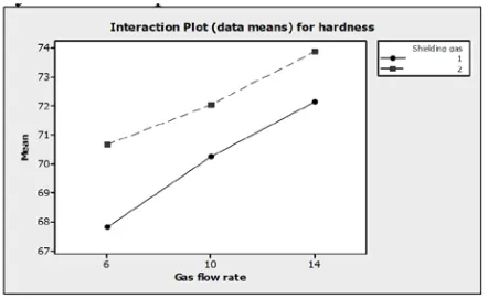
Prachya peasuraa, Anucha Watanapab studied the effect of shielding gas parameter on mechanical properties and microstructures of heat-affected zone and fusion zone on gas tungsten arc welding (GTAW) in aluminium alloy AA 5083. The factorial experiment was designed for this research. The factors of AA 5083 weld used in the study types of shielding gas in argon and helium, gas flow rate at 6, 10 and 14 litres per minute. Then the results were using microstructure and Vickers hardness test[2]
Results of hardness in heat affected zone : .
Fig. 4 Interaction plot for hardness in HAZ
Mechanical property test, hardness of penetration by micro vicker hardness at heat affected zone, 5 points was determined from the average of 18 samples. General linear model of the hardness versus type of shielding gas and gas flow rate was studied.It was indicated that the type of shielding gas and interaction hardness at the level of confidence 95% (P-Value <0.05). Performance analysis of the results of the main factor is type of shielding gas and gas flow rate.Factors could explain the variability of the response of hardness 96.49%.
As shown in figure 2, interaction plot of hardness, Found that the type of shielding gas flow rate interaction hardness. The pull factors that result in a hardness most argon and gas flow rate 14 l/min. Factors used in the type
of shielding gas and gas flow rate of the P-Value of factors was 0.000 (<0.05). The result showed that the type of shielding gas and gas flow rate with electrification interaction significance at the maximum hardness was 74.27 HV.
Results of hardness in fusion zone :
Probability plot of hardness in fusion zone the data has normal distribution P value > 0.05. General linear model of the hardness was versus type of shielding gas and gas flow rate was studied and it was found that the type of shielding gas and interaction hardness at the level of confidence 95% (P-Value <0.05).
This indicated that data could be predicted using model that was to be generated. The R2 of this collected data was about 95.18% which response could be described
by the experimental factors. The result showed that the type of shielding gas flow rate interaction hardness in fusion zone. The pull factors that result in a hardness most argon and gas flow rate 14 l/min. Factors used in the type of shielding gas and gas flow rate of the P-Value of factors was 0.000 (<0.05). The result showed that the type of shielding gas and gas flow rate with electrification interaction significance at the maximum hardness in fusion zone at 68.97HV.
Fig. 5 Interaction plot for hardness in fusion zone
25
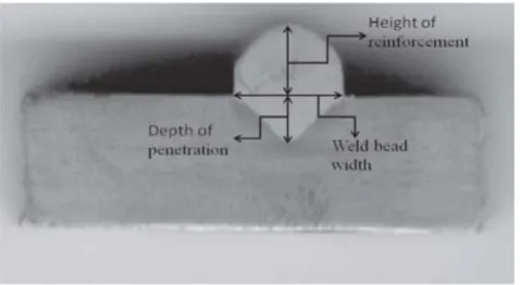
Fig. 6 Nomenclature of welded portion Main effects of Process Parameters :
Main effects of current, voltage and NTD on dilution could be studied. When the current increases dilution because of the reason that due to high welding current, heat input per unit length of the weldbead increases, which increases the depth of penetration. Moreover molten droplets at the tip of the filler wire, which become the part of the weld pool are also overheated, so this extra heat and the increased momentum of the droplets is the reason for increased penetration and hence dilution.
When the voltage increases dilution increases. This may due the fact that the arc cone increases with increase in voltage, thereby spreading the arc over a greater area of the base metal. When the distance between nozzle and workpiece (NTD) increases dilution decreases. This is due to excessive heating when NTD is short and poor gas efficiency when NTD is long.
Calculation of dilution :
Dilution = Ap /(Ap+Ar) where,
Ap = Penetration area Ar = Reinforcement area
Fig. 7 Bead Geometry
Interaction effects of Process Parameters on Dilution :
Study of interation plots of effect of current, voltage and NTD gave satisfactory explanations about thenteraction effects of the process parameters on the bead geometry is evident that dilution increases with increase in voltage but it decreases at low level of both the current and NTD. This may be due to the fact that at this level metal deposition
rate is too low. It is evident that dilution increases with increase in current for all levels. This is due to the high deposition rate. As the nozzle to work distance increases Dilution decreases.
G. Lothongkum, E. Viyanit, P
Bhandhubanyong carried out an experimental study. The TIG pulse welding parameters of AISI 316L stainless steel plate of 3 mm thickness at the welding positions of 6±12 h were investigated. The weld bead pro®les corresponded to DIN 8563 class BS. The studied parameters were welding speed, pulse/base currents, pulse frequency, and % on time. Pure argon and argon with nitrogen contents of 1±4 vol.% were used as shielding gas with a fow rate of 8 l/min at both the top and the back sides of welds. Preliminary welding results at the 6 h welding position showed that the appropriate parameters were: base current of 61 A, pulse frequency of 5 Hz, and 65% on time.
With these constant parameters the effects of welding speeds of 2±8 mm/s and nitrogen contents of 0±4 vol.% in argon shielding gas on pulse currents were examined to attain acceptable weld bead profile corresponding to DIN 8563 class BS with complete penetration. The results showed that the lowest pulse currents were observed at the 9 h welding position. Increasing nitrogen content in argon gas decreases the pulse currents. At the welding positions of 6 and 12 h, the maximum welding speed is limited to 6 mm/s, and with a welding speed of 7 mm/s the formation of slag inclusion at the top of weld metal was observed.
The maximum welding speed of 5 mm/s is found for the welding positions of 8, 9, 10 h, but the welding speed of 6 mm/s is not applicable because of incomplete filled groove. The depth/width ratios (D/W) are between 0.34 and 0.40. Increasing welding speed decreases in the weld width and increases in the D/W ratio. The delta-ferrite contents of the weld metal are about 6±10 vol.%, and are minimum at the welding position of 9 h, because of the high nitrogen content of the cover gas and lowest pulse currents compared to all other welding positions. Radiography showed acceptable weld beads free of porosity.
III.
CONLUDING REMARKS
It is reported that the strength of a welded joint is largely determined by the dimensions and shape of its bead. The profile of the bead has significant influence on the welding. From the cross-sectional area of the bead, the cooling rate of the weldment can be judged. Bead cross-sectional area along with the bead height (BH) and width determines the residual stresses and thus, distortion of the welded structure.
26
Due to the above reasons, the mechanicalproperties of welded structure are dependent on the size and shape of the weldment.
From above literature review it is indicated that following are the major process parameters which affect the weld bead geometry in GTAW.
• Welding current
• Arc voltage
• Welding speed
• Type of shielding gas
• Shielding gas flow rate
They affect the weld quality in terms of
• mechanical properties such as ultimate tensile strength
• weld bead geometry (weld penetration, weld height
and width of the weld).
The control of above mentioned process parameters leads to achievement of quality weldments in GTAW process.
REFERENCES
[1] Mohd. Shoeb, Prof. Mohd. Parvez, Prof. Pratibha Kumari “Effect of MIG welding input process parameters on weld bead geometry on HSLA Steel”, International Journal of Engineering Science and Technology (IJEST), Vol. 5, No. 01, January 2013, pp. 200-212
[2] Palani. P. K., Saju M., “Modelling and Optimization of Process Parameters for TIG Welding of Aluminium-65032 Using Response Surface Methodology”, International Journal of Engineering Research and Applications, Vol. 3, Issue Issue 2, March -April 2013, pp.230-236
[3] Prachya Peasuraa, Anucha Watanapab, “Influence of Shielding Gas on Aluminium Alloy 5083 in Gas Tungsten Arc Welding”, 2012 International Workshop on Information and Electronics Engineering (IWIEE), Procedia Engineering 29 (2012) 2465-2469
[4] Vipin Kumar, Gajendra Singh, Mohd. Zaheer Khan Yusufzai, “Effect of process parameters of Gas Metal Arc Welding on Dilution in Cladding of Stainless Steel on Mild Steel”, MIT International Journal of Mechanical Engineering, Vol. 2, No. 2, August 2012, pp.127-131
[5] G. Lothongkum, E. Viyanit, P. Bhandhubanyong, “Study on the effects of pulsed TIG welding parameters on delta-ferrite content, shape factor and bead quality in orbital welding of AISI 316L stainless steel plate”, Journal of Materials Processing Technology 110 (2001) p.p. 233-238