Study on Wind Analysis of Multi-Storied Building with Regular
and Irregular Plan
Adarsh S B
*, Sridhar R
***(Department of Civil Engineering, Nagarjuna College of Engineering and Technology, Bengaluru, India) **(Professor, Department of Civil Engineering, Nagarjuna College of Engineering and Technology, Bengaluru
, India)
1. Introduction
In general, for the design of tall buildings, both wind as well as earthquake loads needs to be considered. Governing criteria for carrying out analyses for earthquake loads and wind loads are different. As per IS 875(Part 3):1987, when wind interacts with a building, both positive and negative pressures occur simultaneously, the building must have sufficient strength to resist the applied loads. Load exerted on the building is transferred to the structural system then passing through the foundation and finally transferred to the ground. The wind pressure is basically a function of exposed basic wind speed, topography, building height, exposed area and shape of the building. Two load cases govern thedesign of high rise structures, besides dead & live loads: Earthquake loads and wind loads. Here we have concentrated on wind loads. It drastically changes the behaviour of high rise structures as the height and wind speed increases. Usually shear wall is used in the high rise building. To carry out the modelling and analysis for 12 storey building E-TABS software is used.To study the wind motion on thesemodelsthe structure for static shear wall and steel bracing are used. Comparison of the regular and irregular structures for dynamic properties was studied through the results of displacement, bending moment and storey drift.
2. Literatur Reivew
They presented the work on wind analysis of multi-story buildings with different lateral load resisting system for different aspect ratio. The modelling and analysis is done by using E-TABS software and the total forty five models are prepared. They suggest that RC shear wall is better to resist lateral loads compared to RC double bracing. they conclude that RC shear wall act as better lateral load resisting element compared to double bracing system and also reduce the drift and displacement.
Comparative study of the wind and earthquake is done on a high rise building by using the Indian standard codes such as IS: 875 (Part 3) – 1987 and IS: 1893 (Part 1) – 2002 respectively and also by using STADD-PRO. Analytical Method given in the code IS: 875 (Part 3) - 1987 which is usually acceptable for a building with regular shape and size and is almost based on the geometric properties of the building and without incorporating the effects of the nearby buildings. As the wind speed increases My, Mz and Fy ,Fz values also increases according to the category, opening as compare to Mz and Fz values My and Fy values increased more rapidly. Displacement increases as the wind speed increases for various types of opening, category.
Abstract: ETABS 2015 (Extended three dimensional analysis of building system) is the tool to analysing the multi-storey structure. In this study the effect of wind on multi storied structure for the plan of regular and irregular is observed. In addition, the effect of shape on wind analysis is also discussed. The comparison of impact of wind for Rectangular, and U-shape, building structure is presented. The post analysis consist typical characteristic comparison related to storey displacement, storey drift, time period, etc. The categorization of structure as Class-B of wind code consideration for height is used for modelling of structure. Modelling of as category-2 is taken constant to compare the result. This study of structure for plan of regular and irregular concludes that shape of the structure is more dominant for story displacement, story drift, time period etc. and also shape of the structure will play role on safety of the structure against wind effect.
Presented the work on analysis and design of (G+15) Stories under the effect of earthquake and wind for Composite, Steel and RCC building such as story displacement, story drift and Maximum bending moment and shear forces. They suggest that composite structure is better option compare to RCC and Steel.
They presented the work on structural analysis of multi-story building under the effect of wind load for composite structure for different irregular plan. The modelling and analysis is done by using E-tab software. And they compare the result of different plan configure ration building such as storey drift, base shear, and comparative study. they conclude that the composite frame are light in weight which reduces the dead load on structure that can reduce the load of building. And the displacement in U-shape structure increases abruptly as increase in height of storey.Analysis suggest that rectangular structure for along wind or across wind direction is preferable due to large stiffness and less displacement against wind
3. System Development
In this study a multi-storied building of Regular 42720X18935mm Irregular plan-30802.88X26499.98mm plan dimension is considered and the building is considered as residential building. The structural property and dimension are given below. and also Fig.1shows the basic plan of regular and irregular residential building.The residential building isanalyzed for different load combination such as dead load, live load, and wind load as per IS Code 875(part-3)-1987.Various specification of loading taken for the study as shown in Table.1.
Plan Veiw of Regular and Irregular Building:
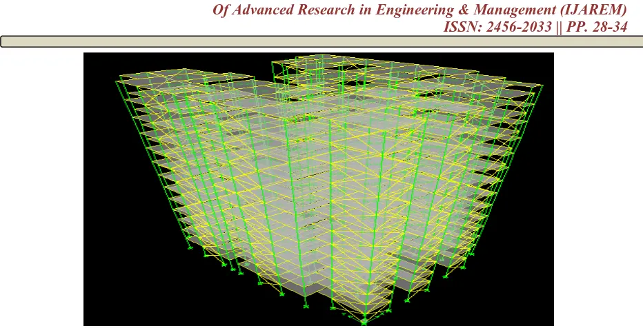
3D VIEW OF REGULAR BUILDING
Figure 2:3D view of regular building with shear wall and steel bracing
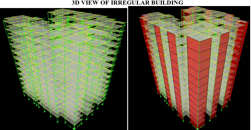
3D VIEW OF IRREGULAR BUILDING
Figure 3:3D view of irregular building with shear wall and steel bracing.
Table 1: Specification of Building
Plan dimension Regular=42720X18935mm
Irregular=30802.88X26499.98mm
Regular building height 39m
Irregular building height 39m
Height of each storey 3m
Thickens of each slab .125,.150m
Thickens of wall .20,0.15m
Table 1 gives the specification of the building which contain the height of the building, dimension, thickness of the slab and wall of the building.
Table 2: Material Properties
Grade of concrete M30,M35,M40
Grade of steel Fe 415,500
Density of concrete 25 Kn/m3
Density of brick 20 Kn/m3
Table 2 gives the material property of the structure which is used during the modelling of the project. it contains a grade of concrete, steel and density of brick and concrete.
Table 3: Specificaton of Loading
Live load 2Kn/m2
Floor load 1.5 Kn/m2
Wall load 11.25 Kn/m2
Basic wind speed 50m/s
Terrain category 2
Structure class B
Risk co-efficient(k1) 1
Topography factor(k3) 1
Rcc design code IS 456:2000
Wind design code IS 875:1987(part 3)
Table 4: Specificaton of Residential Building
COMPOSITE SECTION
Beam 300X500mm
Column 1 300X450mm
Column 2 300X600mm
Column 3 300X750mm
Column 4 300X900mm
Column 5 300X1000mm
Column 6 300X1200mm
Column 7 450X900mm
Column 8 450X1000mm
Column 9 450X1200mm
Table 4 gives the specification of residential building which contain the dimension of the beam and column which is used in the modelling of the project.
Total six number of Residential building are considered for modelling using finite element based software E-TABS. Indian standard code of practice for design load (other than earthquake for building)IS 875(part 3):1987 is used for computing basic wind speed (Vb),Wind pressure, and Terrain, height and structure size factor(k2)etc
Storey Displacement
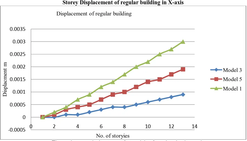
Storey Displacement of regular building in X-axis
Figure 4:Story Displacements for models of regular plan in x-axis.
The figure4 shows the storey displacement for a regular plan and shows the values of UX. In this graph x-axis is No. of storey and in y-axis is storey displacement in mm. As the storey height increases the displacement of the storey also increases with height.
-0.0005 0 0.0005 0.001 0.0015 0.002 0.0025 0.003 0.0035
0 2 4 6 8 10 12 14
Di
spl
ac
m
e
n
t
m
No. of storyies Displacement of regular building
Storey Displacement of irregular building in Y-axis
Figure 5:Story Displacements for models of irregular plan in y-axis.
The figure 5 shows the storey displacement for a irregular plan and shows the values of UX. In this graph y-axis is No. of storey and in y-axis is storey displacement in mm. As the storey height increases the displacement of the storey also increases with height.
Storey Drift
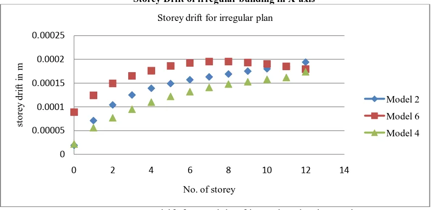
Storey Drift of irregular building in X-axis
Figure 6:
Story drift for models of irregular plan in x-axis
.The figure 6 shows the storey drift forairregular plan and shows the values of UX. In this graph x-axis is No. of storey and in y-axis is storey drift in mm. As the storey height increases the drift of the storey also increases with height
0 0.001 0.002 0.003 0.004 0.005 0.006 0.007
0 2 4 6 8 10 12 14
Di spl ac m e n t in m
No of storey
Displacment of irregular plan
Model 2
Model 4
Model 6
0 0.00005 0.0001 0.00015 0.0002 0.000250 2 4 6 8 10 12 14
st o re y dr if t in m
No. of storey
Storey drift for irregular plan
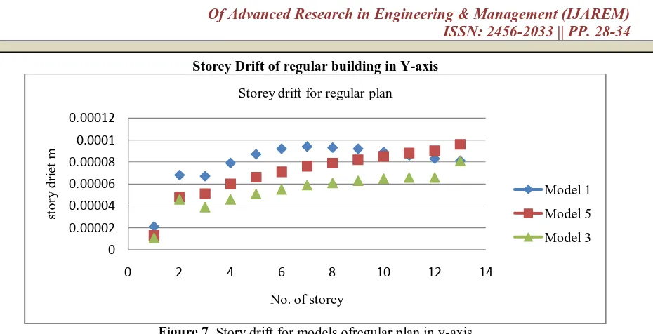
Storey Drift of regular building in Y-axis
Figure 7. Story drift for models ofregular plan in y-axis
The figure 7 shows the storey drift for a regular plan and shows the values of UX. In this graph x-axis is No. of storey and in y-axis is storey drift in mm. As the storey height increases the drift of the storey also increases with height
Conclusion
Overall analysis suggests rectangular structure for along wind or across wind direction is preferable due to large stiffness and less displacement against wind.
In High rise structure the wind pressure is mainly depends on exposed area of building against the wind intensity So that the exposed area of building need to be altered or needs to deviate to some angle to reduce wind pressure.
RC shear wall acts as better lateral load resisting element when compared to the RC double diagonal bracing.
The presence of RC shear wall influences the overall behaviour of structures when subjected to lateral forces. Hence RC shear wall can be considered as displacement and drift control structural element.
The structure with U shaped plan is more sensitive to the wind load as compared to rectangular shaped plan and hence less cost effective and serviceable.
The displacement in shape structure increases adruptly as increases in height of storey so that U-shape structure is no preferable in wind prone zone
Reference
[1]. AbhayGuleria, Structural Analysis of a Multi-Storeyed Building using ETABS for different Plan Configurations, International Journal of Engineering Research & Technology (IJERT), 3(5), May 2014, [2]. Bhumika Pashine1, V. D. Vaidya2, Dr. D. P. Singh3 Wind analysis of multi-storied structure with T
shape and L Shape geometry 2016 IJEDR | Issue 3, Volume 4,
[3]. Chandradhara G. P1, Vikram.M.B2 Effect of wind load on the aspect ratio of the building IOSR Journal of Mechanical and Civil Engineering (IOSR-JMCE) e-ISSN: 2278-1684, p-ISSN: 2320-334XJawad Ahmed, H S Vidyadhar, Wind Analysis and Design of Multi Bay Multi Storey 3D RC Frame, International Journal of Engineering Research & Technology (IJERT), 2(9), September 2013, [4]. shaikhmuffassir , l.g. kalurkar study of wind analysis of multi-story composite structure for plan
irregularity international journals of advanced technology in engineering and science issue no.9, vol.no4,september2016 Swati D.Ambadkar and Vipul S. Bawner, Behavior of Multi story Building under the Effect of Wind load, International Journal of Applied sciences and Engineering research (IJASER), 1(4), 2012, Syed Rehan and S.H.Mahure, Study of Seismic and Wind Effect on Multi Storey R.C.C. Steel and Composite Building, International Journal of Engineering and Innovative Technology
0 0.00002 0.00004 0.00006 0.00008 0.0001 0.00012
0 2 4 6 8 10 12 14
st
o
ry
dr
ie
t
m
No. of storey
Storey drift for regular plan