ISSN: 2334-2986 (Print), 2334-2994 (Online) Copyright © The Author(s). All Rights Reserved. Published by American Research Institute for Policy Development DOI: 10.15640/jea.v3n1a1 URL: http://dx.doi.org/10.15640/jea.v3n1a1
Utilizing Laser Cutting, 3D Printing and 3D Scanning to Create an Affordable Fully
Interactive Prototype of a Full Size Animatronic Figure
Christopher W. LaMorte
1& Haowei Wang
2Abstract
This paper offers a systematic approach to a low cost method to manufacture a fully interactive animatronic figure from readily available technology. A very low cost German shepherd animatronic figure prototype is manufactured in this research. The prototype is capable of neck, jaw and tail movements as well as sound. The jaw, neck, and tail movement mechanisms are powered by servo motors. Arduino programming is used to synchronize the movement of the various mechanisms, including moving the jaw to the audio source. The manufacturing techniques include laser cutting, additive manufacturing and 3D scanning. The electrical hardware includes a microcontroller and a power supply. A Spark Fun Inventor’s kit is used to combine the Arduino programs with the hardware. This helps to coordinate the audio and the overall animatronic figure movements. The goal of this research project is to introduce into the public domain low cost commercially available technology for manufacturing animatronic figures and to provide a cost efficient alternate manufacturing method to the entertainment industry.
Keywords: Animatronics, laser cutting, additive manufacturing, 3D scan
1. Introduction
Animatronics has over 2000 years of history. Archytas of Tarentum in 280 BC constructed a wooden pigeon that moved in a circular motion using compressed air (Foran, 2015).The astronomical clock in Prague installed in 1410 is still in use today. Leonardo da Vinci created an armored knight robot that could sit, stand, raise its visor, and maneuver its arms. It was first displayed at the court of Milan in 1495. Today animatronics is commonly used in the entertainment industry such as in amusement parks (Guarino, 2012; Oberg, 2012; Peel, 2008; Philpot, 2011). The most advanced figure to date is Disneyland Resort’s Mr. Potato Head. He is featured in Disney’s Toy Story Mania attraction. He can look directly at the person he is talking to through digitally animated eyes, as well as remove and re-attach his ear. Due to advancements in programming, his mouth has a wide range of lip movements. Disney’s 11 parks around the world use more than 5000 animatronic figures, including gorillas, dinosaurs, pirates, and ghosts. Their popularity makes it unlikely that they will be replaced by digital projected images anytime soon. However, due to the complex mechanical and electrical systems, programming requirements, and the high costs associated with design and materials, affordable techniques for manufacturing animatronic figures have not yet entered the public domain. The high cost of manufacturing is also a concern for profit generation in the private sector. This research paper provides an alternative method to manufacture such figures at a very low cost using modern technology. This research project offers a systematic approach to build a fully interactive animatronic figure in this case, a German shepherd dog, from readily available technology at minimal cost.
1
Graduate Student, Department of Mechanical Engineering, California State University Fullerton, Fullerton, CA 92831 2
2. Mechanical Design
The jaw, neck, and tail movement mechanisms are powered by servo motors. These movements as well as the movements of the jaw to the audio source are synchronized using Arduino programming. The manufacturing techniques include laser cutting, additive manufacturing and 3D scanning
2.1 Servo Motors
Figure 1 shows a Pulse Width Modulation wave (PWM), which is the underlying principle of how servo motors operate.
Figure 1: Pulse Width Modulation Wave
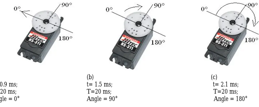
In this example the pulse width t has a minimum of 0.9 ms and a maximum of 2.1 ms, whereas T is repetition rate. The t part of the wave is the portion in which +5 V amplitude is being provided and the rest of the time 0 V is given out. The variance between the 0.9 ms and the 2.1 ms is what directs the servo to move and tells it where to go. The angle or movement of a servo can be controlled by the pulse width t and the repetition rate T. Most servos have a sweeping range of between 90° and 180°. The neutral position of the servo is defined to be the position where the servo has exactly the same amount of potential mechanical rotation in the clockwise direction as it does in the counter clockwise direction. Figure 2 shows three sets of t and T values and the angles they generate. Servos capable of a 180° sweeping angle are chosen for this project to achieve a wide range of movement.
(a) t= 0.9 ms; T=20 ms; Angle = 0°
(b) t= 1.5 ms; T=20 ms; Angle = 90°
(c)
t= 2.1 ms; T=20 ms; Angle = 180°
Figure 2: Servo Position in Degrees with Varying t Values
Table 1: Mechanism and Servo Specifications
Mechanism Motor Speed [°/s] Stall Torque [kg·cm]
Jaw 600 16.5
Tail 600 16.5
Neck Yaw 333 40
Neck Pitch 333 40
(a) Turnigy 1270HV digital servo motor (b) Track Star TS-T17HV digital servo motor
Figure 3: Servo Motors Used in the Construction of the Final Prototype
2.2 Jaw Mechanism
A one-degree of freedom mechanism was created for the jaw. Its movement consists of rotating around a fixed point similar to a human jaw. The average distance that a German shepherd dog opens its jaw is estimated at 50 mm based on the measurement of Christopher LaMorte’s pet dog. A model is created in Solid Works as shown in Figure 4.
Figure 4: Jaw Grash of Four bar Mechanism
The jaw double crank mechanism is a four-bar linkage. The double crank converts rotary motion from the first crank to a second crank. Position analysis of the Grash of four bar mechanism is shown in Figure 4. The first crank (bar 2) is the servo arm, the second (bar 4) fits onto the back of the mouth. The coupler link (bar 3) is hinged at both ends. Bar 1 is not visible. It connects the two fixed points on the animatronic figure. It is important to note that the servo arm pivot and the hinge point should be directly in line with one another as is the case in the Grash of four bar mechanism.
Figure 4: Position Analysis of a Grash of Four Bar Mechanism (Norton, 2004)
A metal geared high torque servo motor is used to actuate the jaw mechanism. The advantage of this setup is that it provides extra torque that allows the jaw to be locked in place if the mouth needs to be opened or closed for any length of time. The motor is placed on a platform above the jaw. At a 90° angle with the attached linkage, the servo arm provides the most torque. The mechanism is designed to sweep a total of 90°.
2.3 Moving the Jaw to the Sound
The following components are used to achieve movement of the jaw to sound: an Arduino Uno microcontroller board, a 1Kohm resistor, a servo motor, jumper wires, a 3.5 mm audio jack pinout, and a soldering iron. The audio jack cable is cut into two halves to expose the three wires. They are ground (white), right audio (yellow) and left audio (red). The ground and audio wires are then tinned and each is soldered to a jumper wire. A resistor is soldered to the ground wire to provide a load. The jumper wire is connected to one of the audio source wires and is then connected to the Analog 0 pin on the Arduino Uno board. The resistor is connected to ground. The Arduino Uno board is then connected to a computer to make sure a sound source produces signals. The signal reading goes up in value with louder sound, which proves the setup is correct. Then the servo motor is connected to the jumper wires. The black wire goes to ground on the Arduino Uno board. The red wire goes to the 5 V source and the white wire is connected to output pin 9. Programming in Arduino is last finished to synchronize the movement of the servo motor with audio source.
2.4 Neck Mechanism
Figure 5: Neck Mechanism
2.5 Tail Mechanism
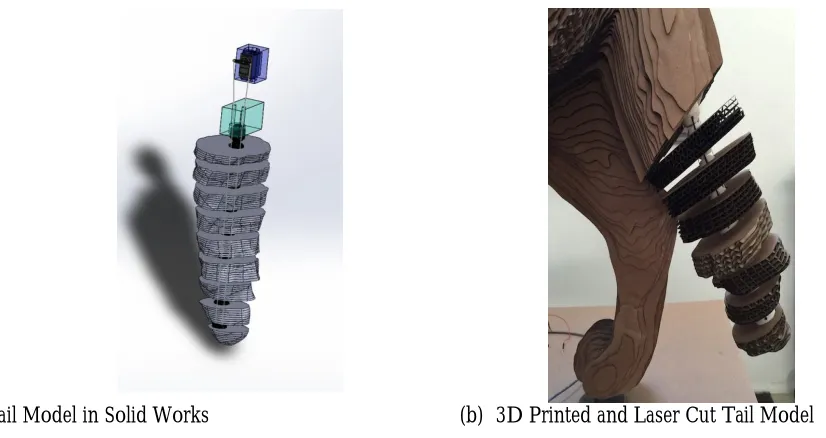
Nine individual vertebra pieces that make up the tail assembly are designed in Solid Works as shown in Figure 6(a). The actual model is both 3D printed and laser cut and is presented in Figure 6(b).
(a) Tail Model in Solid Works (b) 3D Printed and Laser Cut Tail Model
Figure 6: Tail Mechanism
Multiple elastic cords are strung through each side of the vertebra pieces so that the tail returns to its original position after being moved or when the power is off. The spring constant of the cord is 0.424 oz/in. Six cords in parallel are used to achieve a total spring constant of 2.544 oz/in.
3. Construction
3.1 3D Scanning
3.2 Laser Cutting
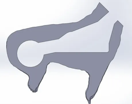
Laser cutting is a method of cutting a design using a CAD file converted to gcode to direct the cutting path. A carbon dioxide laser cuts by polarizing and focusing a bean of high power laser light on the medium. The cutting head is coupled to a CNC system which directs the position of the head allowing it to follow a very specific and detailed line prescribed by the computer program. The beam then melts, burns, or vaporizes the material along the cut line. The model is first split into section of the same thickness (5/32 in) in Solid Works. Figure 7 shows an example of a split part. Then a .dxf file is created from the face of the part in Solid Works. The .dxf file is converted to an Adobe Illustrator file and multiple parts are aligned together so that the cardboard material that is to be cut could be maximized. The laser cutting is achieved by the Full Spectrum Laser Pro LF Series 48x36 CO2 Laser at speed 100 and
power 25.
Figure 7: One of the Solid Works Part Files Generated From Splitting the Original Part
3.3 Materials
Black steel pipe is chosen for the skeleton to make the figure stand still and for stability. Also, it is readily available and has a low cost. The rest of the body including the skin is created with corrugated cardboard sheets of 5/32 in. thickness. Table 2 lists the materials used in the construction of the animatronic figure.
Table 2: Properties of Materials Used in Construction of the Figure
Material Density [lbs/ft3] Relative Strength [ksi]
Steel 489 40
Aluminum 166 30
Polystyrene 55 7
Pine 23 1.1
Cardboard 9.02 0.2
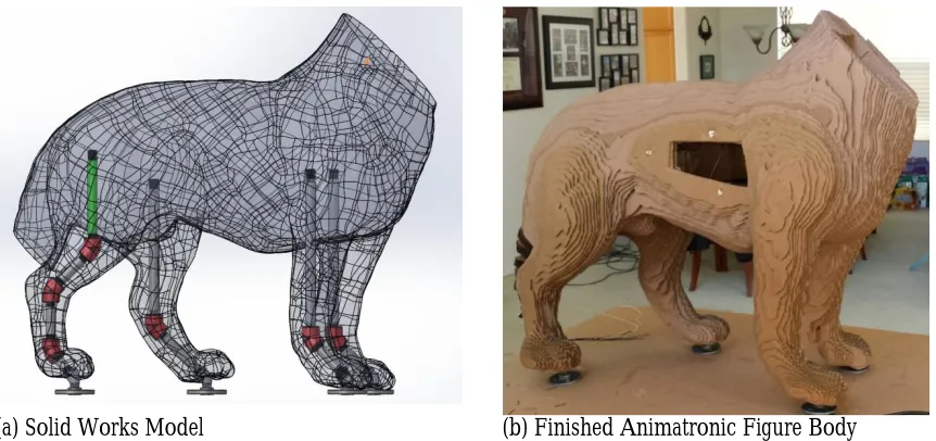
3.4 Adhesive
(a) Solid Works Model (b) Finished Animatronic Figure Body
Figure 8: Animatronic Figure Body Construction
3.5 3D Printing
3D printing is a process that uses a computer aided design and converts the design into thin cross sections that are determined by the 3D printer slicing software. This information is then sent to the 3D printer, which extrudes material layer upon layer creating a 3-dimensional object. This process is also known as Additive Layer Manufacturing. 3D printing is critical to rapid prototyping because of its low cost and fast result. A self-built open source 3D printer model Prusa i3 is used to print custom designed parts to allow for fast prototyping at a low cost. Acrylonitrile Butadiene Styrene (ABS) was used to print parts because of its lightweight. Figure 9 shows a 3D printed gear created for the neck mechanism.
Figure 9: A Spare 3D Printed Neck Mechanism Gear
4. Electrical Hardware and Software
The power supply selected is a MEAN WELL SP-150-7.5. It is capable of converting a 120 V AC source into a DC voltage between 7.13 and 8.25 V. The dimensions of the casing are 199×99×50 mm making it a great choice for the small packaging constraints of an animatronic figure. A Spark Fun Inventor’s kit is used to combine the Arduino programs with the hardware. This helps to coordinate the audio and the overall animatronic figure movements.
5. Results
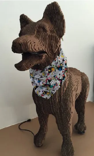
An affordable prototype of a full size animatronic German shepherd dog figure is designed and manufactured using readily available processes including 3D scanning, 3D printing and laser cutting. Figure 10 presents the final figure. The manufactured animatronic dog figure is capable of jaw, neck, and tail movement and the jaw movement is synchronized with the sound source. The total cost was $992.6.
Figure 10: Finished Animatronic German Shepherd Dog Figure
Bibliography
Budynas, R.G., Nisbett, J.K., and Shigley, J.E. (2014). Shigley’s mechanical engineering design. (10th ed.). Boston: McGraw Hill.
Fitzpatrick, R. (2010). Designing and constructing an animatronic head capable of human motion programmed using face-tracking software. Worcester Polytechnic Institute, Worcester, MA.
Foran, R. (2015). Robotics: from automatons to the roomba. Minneapolis: Abdo Publishing.
Guarino, B.D. (2012). Design of an animatronic mermaid: using sensors and motors in an aquatic environment. Brown University, Providence, RI.
Norton, R.L. (2004). Design of machinery: an introduction to the synthesis and analysis of mechanisms and machines. (3rded.). Boston: McGraw-Hill Higher Education.
Oberg, E. (2012). Machinery’s handbook: a reference book for the mechanical engineer, designer, manufacturing engineering, draftsman, toolmaker, and machinist. (29th ed.). New York: Industrial.
Peel, C. T. (2008). An investigation into the construction of an animatronic model. University of Bradford, Bradford, UK.
Philpot, T.A. (2011). Mechanics of materials: an integrated learning system. (2nd ed.). Hoboken: John Wiley. Stephens, K. (2013). Normal neck range of motion. [Online] Available: