[Gomez* 5(11): November, 2018] ISSN 2349-4506
Impact Factor: 3.799
G
lobal
J
ournal of
E
ngineering
S
cience and
R
esearch
M
anagement
A DESIGN AND SIMULATION STUDY OF ZERO-IF GILBERT-CELL MIXER FOR
WIMAX RECEIVERS
Frederick Ray I. Gomez
*
New Product Introduction Department, Back-End Manufacturing & Technology, STMicroelectronics,
Inc. 9 Mountain Drive, Light Industry & Science Park II, Brgy. La Mesa, Calamba City, Laguna,
Philippines 4027
DOI: 10.5281/zenodo.1745378
KEYWORDS
:
Gilbert-cell mixer; double-balanced mixer; zero-IF; WiMAX; conversion gain; noise figure.ABSTRACT
Differential approach is becoming highly preferred in RFIC (radio frequency integrated circuit) design due to its advantages, particularly its high immunity to common-mode noises, satisfactory rejection of parasitic coupling, and increased dynamic range. One particular RF front-end building block that is often designed as differential circuit is the mixer. This paper presents a study and design of a differential mixer, particularly the Gilbert-cell or double-balanced mixer implemented on a zero-IF (zero-intermediate frequency) or direct-conversion architecture in a standard 90nm CMOS (complementary metal-oxide semiconductor) process operating at frequency of 5GHz, which is a typical frequency for WiMAX (worldwide interoperability for microwave access) receiver. Impedance matching was necessary to fully optimize the mixer design. The zero-IF Gilbert-cell mixer design achieved conversion gain of 11.46dB and noise figure of 16.53dB, comparable to other mixer designs.
INTRODUCTION
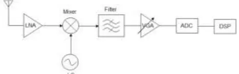
Receiver front-end of an RF (radio frequency) system is of particular interest to many designers and researchers as it proves to be the most critical part in many communication systems and wireless applications such as WiFi (wireless fidelity), Bluetooth, and WiMAX (worldwide interoperability for microwave access). The block diagram of a typical receiver is shown in Fig. 1.
Fig. 1. Block diagram of a typical receiver.
Mixer is one of the key front-end building blocks in an RF receiver. It is also called a converter because it converts RF signals into a lower intermediate frequency (IF) by mixing with an offset local oscillator (LO). Depending on the receiver requirements, mixers must undergo a careful design process since a lot of tradeoffs among different performance parameters must be considered and understood. Ultimately, the objective is to study and design a zero-IF Gilbert-cell mixer implemented in a standard 90nm Complementary Metal-Oxide Semiconductor (CMOS) process. Operating frequency is set to 5GHz, which is a typical frequency for a WiMAX receiver.
REVİEW
OF
RELATED
LİTERATURE
[Gomez* 5(11): November, 2018] ISSN 2349-4506
Impact Factor: 3.799
G
lobal
J
ournal of
E
ngineering
S
cience and
R
esearch
M
anagement
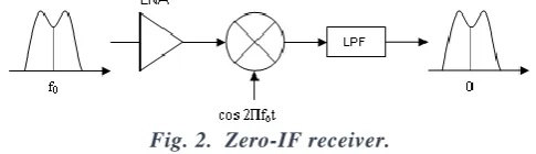
cutoff characteristics, and thus allowing the possibility of monolithic integration. With this, smaller and cheaper receivers with low power consumption may be realized for various wireless applications like Bluetooth, WiFi, and WiMAX. Many of the implemented receivers in WiMAX [3] [4] [5] use the zero -IF architecture since the LPFs make sure that the closely-spaced carrier signals do not cause interference with each other.Fig. 2. Zero-IF receiver.
Designing a mixer must take into account the many trade -offs among the performance parameters. Thus, a careful study of these important parameters must be done in order to design fully -functional mixers. A mixer’s efficiency on frequency conversion from RF to IF is characterized by conversion loss or gain. It is the ratio of the desired IF output to the value of the RF input. Conversion gain (CG) may be expressed in voltage or power. In cases when the conversion gain is less than u nity or 0dB, it is aptly termed as a conversion loss.
𝑪𝑮𝒗𝒐𝒍𝒕𝒂𝒈𝒆= 𝟐𝟎𝒍𝒐𝒈
𝑽𝑰𝑭
𝑽𝑹𝑭
Eq. (1)
𝑪𝑮𝒑𝒐𝒘𝒆𝒓= 𝟐𝟎𝒍𝒐𝒈
𝑷𝑰𝑭
𝑷𝑹𝑭
Eq. (2)
VIF and VRF are the root mean square (RMS) voltages of the IF and RF signals, respectively, while PIF and
PRF are the equivalent power of the IF and RF signals, respectively. Conversion gain is preferred over
conversion loss because of the benefit of amplification along with frequency translation. However, it should be noted that conversion gain directly affects the noise figure and linearity of the overall receiver. Hence, design tradeoffs concerning these parameters are inevitable.
Another important mixer parameter is the noise figure (NF). It is a measure of the amount of signal-to-noise-ratio (SNR) degradation introduced by the mixer as seen at the output. Eq. 3 shows the relation between the SNR at the input port and the SNR at the output port of the mixer, often expressed in dB.
𝑵𝑭 = 𝟏𝟎𝒍𝒐𝒈 (𝑺𝑵𝑹𝑰𝑵 𝑺𝑵𝑹𝑶𝑼𝑻
) Eq. (3)
Noise figures of mixers tend to be higher than amplifiers (e.g. low-noise amplifiers, power amplifiers) because of the contribution of noise from other frequencies (apart from input RF signal) that can mix down to the IF. This considerable noise in mixers is the main reason why low-noise amplifiers (LNA) are used in the front-end of a receiver [6].
[Gomez* 5(11): November, 2018] ISSN 2349-4506
Impact Factor: 3.799
G
lobal
J
ournal of
E
ngineering
S
cience and
R
esearch
M
anagement
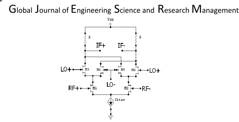
Fig. 3. Gilbert-cell or double-balanced mixer.
As earlier mentioned, the goal of the paper is to study and design a zero -IF Gilbert-cell or double-balanced mixer implemented in a standard 90nm CMOS process, operating at frequency of 5GHz which is a typical frequency for a WiMAX receiver. The target specifications of the figures of merit are based on the performance comparison in terms of conversion gain and noise figure of past researches on direct -conversion active mixer topologies given in Table 1.
TABLEI. PERFORMANCE COMPARISON
Paper RF (GHz) Conversion Gain (dB) Noise Figure (dB) Topology
[4] 2~11 21.5~22.8 21.5~25.8 Double-balanced
[5] 3.4~3.85 10 10 Single-balanced
[9] 2 19.5 10.2 BiCMOS Double-balanced
[10] 20~40 16 -- BiCMOS Single-balanced
[11] 5.2 9.3 10.5 Double-balanced
DESIGN
OF
MIXER
The topology of Gilbert-cell mixer can provide high conversion gain, very low noise figure, and high degree of LO-IF isolation. The main disadvantage of this topology is its physical implementation. A balun transformer is required to convert the single-ended input to a differential RF input signal of the mixer. Transformers with very low insertion loss are difficult to realize in monolithic integration, hence this forces the use of an off-chip transformer which occupies more board space and cost [8].
[Gomez* 5(11): November, 2018] ISSN 2349-4506
Impact Factor: 3.799
G
lobal
J
ournal of
E
ngineering
S
cience and
R
esearch
M
anagement
Fig. 4. Schematic design of Gilbert-cell mixer.
One way to increase the performance of the mixer in terms of conversion gain and noise figure is to apply impedance matching in the circuit. Z11 and Z22 can be obtained using sp-analysis which is swept from f1=
700MHz to f2 = 6GHz. Actual inductor and capacitor values at f = 5GHz can be computed from the L
-network reactances.
To supply differential LO input to the mixer, a port PORT2 with a matching resistor (set to 50Ω) is used
which is then fed into an ideal passive balun to convert the single-ended signal into differential. For the differential RF input of the mixer, same setup as the LO is used with PORT1. To use the differential output for measurements, matching the IF output port PORT3 to the output impedance of the mixer is necessary.
PORT1 is set to DC source type with pacmag (periodic ac magnitude) set to 1. PORT3, which is the IF port, is set also to DC source type. The only large signal is from PORT2 which is a sine wave with flo=5GHz and PLO = 0dBm.
For the impedance matching, the input matching network is applied before the differential RF input of the mixer instead of placing it before the balun. This will result to an adjustment on the value of L1, which will
decrease, since the balun circuit has self-inductance. The adjusted value of L1 can be determined using the sp-analysis swept from f1= 700MHz to f2 = 6GHz. Moreover, inductors with small inductances are more
realizable in actual designs than their larger counterparts. The final values of the L -matching network are summarized in Table II.
TABLEII. FINAL VALUES OF L-NETWORK ELEMENTS
L and C Value
1
L 12.7nH
1
C 1.116087pF
2
L 1.328515nH
2
C 267.127fF
[Gomez* 5(11): November, 2018] ISSN 2349-4506
Impact Factor: 3.799
G
lobal
J
ournal of
E
ngineering
S
cience and
R
esearch
M
anagement
Length, D 300µm 190µm
Metal width, W 10.886µm 10.901775µm
Spacing, S 1 1
No. of turns, N 4.25 2.5
Metal layer 7 7
Inductance, L 12.711454nH 1.328515nH
Q-factor, Q 2.32165 5.693986
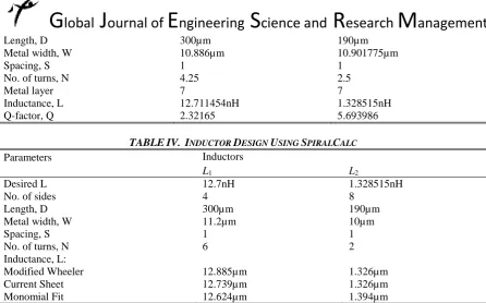
TABLEIV. INDUCTOR DESIGN USING SPIRALCALC
Parameters Inductors
L1 L2
Desired L 12.7nH 1.328515nH
No. of sides 4 8
Length, D 300µm 190µm
Metal width, W 11.2µm 10µm
Spacing, S 1 1
No. of turns, N 6 2
Inductance, L:
Modified Wheeler 12.885µm 1.326µm
Current Sheet 12.739µm 1.326µm
Monomial Fit 12.624µm 1.394µm
In ASITIC, the spiral inductors are designed such that desired inductances are achieved and the Q-factors are optimized with eddy-current option enabled to include the effects of substrate induced eddy current losses. L1
have smaller Q-factor than L2 because of its high inductance value. For the inductor design using SpiralCalc,
same parameter values from the ASITIC parameters are used except for the metal width and the number of turns of the spiral inductor. These parameters are tweaked such that the desired inductances are achieved for the inductors.
The n2port from the analogLib library is used as a model block for all the ASITIC inductors. Touchstone format of S-parameter file is used as file input of the n2port component since the actual S-parameters using ASITIC are given in touchstone format. The figures of merit such as conversion gain and noise figure are determined using SpectreRF in the Analog Design Environment.
DISCUSSION
OF
RESULTS
A Gilbert-cell mixer’s frequency converting action is characterized by conversion gain or loss. Voltage conversion gain is the ratio of the RMS voltages of the IF and RF signals. The formulae for conversion gain are also given in Eq. (1). The variations of conversion gain with the power of LO signal (PLO) can be measured using
[Gomez* 5(11): November, 2018] ISSN 2349-4506
Impact Factor: 3.799
G
lobal
J
ournal of
E
ngineering
S
cience and
R
esearch
M
anagement
Fig. 5. Conversion gain (in dB) vs. PLO of Design2 (w/o matching).
[Gomez* 5(11): November, 2018] ISSN 2349-4506
Impact Factor: 3.799
G
lobal
J
ournal of
E
ngineering
S
cience and
R
esearch
M
anagement
Based on the conversion gain simulation results, input and output impedance matching contribute to better conversion gain performance. Moreover, using ideal inductors for impedance matching produced better performance as compared to using non-ideal ASITIC inductors through the n2port. It can be observed from the simulation plots that the conversion gain of the mixer only is higher than the conversion gain of the whole circuit consisting of the mixer and the balun. This is because the balun in the circuit, which is a passive balun, has insertion loss and thus incapable of producing gain. When a passive balun is cascaded with another block, the overall gain is degraded.
For the noise figure, Pnoise (Periodic Noise) analysis with PSS analysis is used. In addition, PSP (Periodic S-Parameters) analysis with PSS analysis can also be used to determine the noise figure of the circuit. Noise figure from a sweep range of -10dBm to 30dBm can now be determined and plotted using these analyses. The plots are shown in Fig. 8-9.
Fig. 8. Noise figure (in dB) vs. PLO of Design2 (Pnoise analysis).
Fig. 9. Noise figure (in dB) vs. PLO of Design2 (PSP analysis).
[Gomez* 5(11): November, 2018] ISSN 2349-4506
Impact Factor: 3.799
G
lobal
J
ournal of
E
ngineering
S
cience and
R
esearch
M
anagement
TABLEV. SUMMARY OF SIMULATION RESULTS (AT PLO =0)
Figures of Merit Value
CG(mixer+balun) [w/o matching] -17.4308dB
CG(mixer) [w/o matching] -11.4102dB
CG(mixer+balun) [ideal L] 5.44273dB
CG(mixer) [ideal L] 11.4633dB
CG(mixer+balun) [ASITIC L] -10.9662dB
CG(mixer) [ASITIC L] -4.94556dB
Pnoise NF [w/o matching] 125.355dB
Pnoise NF [ideal L] 16.5290dB
Pnoise NF [ASITIC L] 33.7129dB
PSP NF [w/o matching] 8.1267dB
PSP NF [ideal L] 7.1364dB
PSP NF [ASITIC L] 21.4372dB
It is evident that input and output impedance matching contribute to better performance based on the figures of merit presented for the cell mixer design. It is observed that the conversion gain of the zero-IF Gilbert-cell mixer is higher than the conversion gain of the circuit consisting of the mixer and the balun. The reason is that the conversion gain performance at the system-level perspective is greatly influenced by the performance of the initial or preceding blocks, for this case the passive balun. Henceforth, it is of high importance to consider the contribution of the input or previous circuit (and as well as the output or succeeding circuit) in studying and designing the mixer.
CONCLUSIONS
AND
RECOMMENDATIONS
A design of zero-IF Gilbert-cell mixer was implemented and optimized on this study. Proper biasing and sizing of all the transistors were necessary to ensure the required mode of operation for all the transistors. Conversion gain and noise figure were determined to measure the mixer’s performance. These performance parameters can be greatly enhanced by applying impedance matching in the circuit. The effect of the passive balun was also presented, showing the decrease in the conversion gain of the overall circuit. Ultimately, the zero-IF Gilbert-cell mixer design achieved conversion gain of 11.46dB and noise figure of 16.53dB (using Pnoise analysis) at 5GHz, comparable to other mixer designs from past researches.
For future studies, an active balun can be used instead of passive balun for monolithic design and implementation. Active baluns are capable of producing gain and if cascaded in a Gilbert-cell mixer to supply the differential RF and LO inputs, the overall performance of the mixer can be improved. Although active baluns are unidirectional converters, they are also used for their large bandwidth, which is beyond what non-ideal passive baluns can provide.
ACKNOWLEDGMENT
[Gomez* 5(11): November, 2018] ISSN 2349-4506
Impact Factor: 3.799
G
lobal
J
ournal of
E
ngineering
S
cience and
R
esearch
M
anagement
4. J.Y. Lyu and Z.M. Lin, “A 2~11 GHz direct-conversion mixer for WiMAX applications,” IEEE Region 10 Conference, pp. 1-4, Oct. 2007.
5. J.G. Atallah, S. Rodriguez, L.R. Zeng, and M. Ismail, “A direct conversion WiMAX RF receiver front-end in CMOS technology,” International Symposium on Signals, Circuits and Systems, vol. 1, July 2007. 6. T. Lee, “The design of CMOS radio-frequency integrated circuits,” Cambridge: Cambridge University
Press, 1998.
7. G. Watanabe, H. Lau, and J. Schoepf, “Integrated mixer design,” Motorola Inc., Semiconductor Products Sector, Arizona, USA.
8. M. Voltti, T. Koivisto, and E. Tiiliharju, “Comparison of active and passive mixers,” 18th European Conference on Circuit Theory and Design, pp. 890-893, August 2007
9. T. Tikka, J. Ryynanen, M. Hotti, and K. Halonen, “Design of a high linearity mixer for direct-conversion base-station receiver,” in Proc. IEEE International Symposium on Circuits and Systems, 2006.
10. K.W. Hamed, A.P. Freundorfer, and Y.M.M. Antar, “A monolithic double-balanced direct conversion mixer with an integrated wideband passive balun,” IEEE Journal of Solid-State Circuits, vol. 40, no. 3, March 2005.
11. J. Park, C-H. Lee, B-S. Kim, and J. Laskar, “Design and analysis of low flicker-noise CMOS mixers for direct-conversion receivers,” IEEE Transactions on Microwave Theory and Techniques, vol. 54, no. 12, December 2006.
12. A.M. Niknejad and R.G. Meyer, “Analysis and optimization of monolithic inductors and transformers for RF ICs,” in Proc. Custom Integrated Circuits Conference, Santa Clara, CA, pp. 375-378, May 1997. 13. A.M. Niknejad and R.G. Meyer, “ASITIC for Windows NT/2000,” Research in RFIC Design,
http://rfic.eecs.berkeley.edu/~niknejad/Asitic/ grackle/cygwin_info.html.
14. Stanford Microwave Integrated Circuits Laboratory. Integrated Spiral Inductor Calculator, http://www-smirc.stanford.edu/ spiralCalc.html.