Paper received: 21.07.2008 Paper accepted: 25.09.2008 Strojniški vestnik - Journal of Mechanical Engineering 54(2008)12, 850-854
UDC 621.941
Comparative Analyses for Different Modeling Methods in
High Speed Turning Operations for Hardened Steel
Usama U m er1'* Shahid Ikramullah B utt1, Syed Jawid A skari1, Syed Noman D anish', Lijing Xie2 'N ational University o f Sciences and Technology, PNS Jauhar, Karachi, Pakistan
2 Beijing Institute o f Technology, Beijing, China
The modeling o f metal cutting process has been a challenging research topic due to the difficulty in accurate modeling o f the contact and work material deformation with large plastic strain and friction, high temperature and strain rate, and their coupling effect. Among different modeling methods, finite element method (FEM) has proven to be a robust tool in predicting process parameters and optimizing cutting tool geometry. However successful implementation o f a modeling method depends mainly on numerical formulation technique adopted fo r chip formation. The two formulation techniques namely the Lagrangian and the Eulerian have been used in the past by many researchers. Due to the various limitations o f the two approaches, a new arbitrary Lagrangian Eulerian (ALE) method has been adopted fo r the orthogonal high speed turning operations fo r AISI H I 3 hardened steel. This approach does not need any chip separation criterion. For comparative analysis with other techniques, two Lagrangian models with element deletion and node splitting methods were also simulated and compared with experimental data. It has been found that ALE model results are in good agreement with the experimental ones as compared to the Lagrangian models.
© 2008 Journal o f Mechanical Engineering. All rights reserved.
Keywords: high speed machining, process modelling, finite element methods, AISI H13 steel
0 INTRODUCTION
High speed machining (HSM) has emerged as a key technology in rapid tooling and manufacturing applications. Dies and moulds manufacturing represents a significant area o f application for high speed cutting o f cast iron, cast steel and alloy steel. Cost effective high speed cutting o f these difficult to cut materials require advanced tooling like coated carbides, ceramics and poly crystalline cubic boron nitride (PCBN). High speed machining o f hardened steel replaces slow EDM processes in many applications but the productivity is often limited due to frequent tool failures and undesirable surface characteristics o f the workpiece. In order to optimize high speed machining processes, robust models are necessary that can correlate the process variables w ith the cutting parameters and tool geometry. M any investigators have attempted to develop analytical and numerical models to gain a better understanding o f the processes which involve deformation w ith large strains, strain rates and temperatures. Through finite element simulation, one is able to obtain various quantities num erically calculated such as the
spatial distribution o f stresses, strains, temperatures, but the main problem o f those simulations is that we m ust introduce the physics o f the process through very accurate constitutive and contact laws [1].
There had been mainly two formulation techniques for chip formation analysis, the Eulerian and the Lagrangian approach. In the Lagrangian approach, the mesh is attached to the material elements and deformed with the workpiece. In this approach, the analysis can be started from indentation to the incipient stage to steady state. H ow ever it needs an explicit chip separation criterion which is a big problem with the Lagrangian method. The Eulerian approach is more suitable for fluid flow problems involving a control volume [2]. In this method, the mesh consists o f elements that are fixed in space and cover the control volume, and the material properties are calculated at fixed spatial locations as the material flows through the mesh. It does not need any chip separation criterion but is unable to simulate the initial chip formation and experiments are needed to find initial chip shape and geometry.
D ue to these lim itations a n ew m ethod based on A rb itrary E ulerian-L agrangian (ALE) approach has been used. Stresses and tem peratures d istributions are p redicted using A B A Q U S /E xplicit fo r th e orthogonal h igh speed turning operations w hen m ach in in g hardened steel (A IS I-H 13) using PCBN. S im ulations are also run w ith the. traditional L agrangian m odels w ith elem ent deletion and n ode debonds techniques and results are com pared w ith the experim ental data.
1 EXPERIM ENTAL SETUP
Orthogonal turning experiments were conducted with the same cutting parameters on hardened AIS1 H-13 tool steel tubes (50 HRC) using triangular tool inserts having a honed edge preparation and nose radius o f 1.2 mm. The properties and composition o f the workpiece and tool materials are listed in Table 1.Three cutting speeds o f 200, 250 and 300 m/min were used. A constant feed rate o f 0.25 mm/rev and w idth o f cut 2 mm were employed, for all cutting force measurement. Cutting and thrust forces were measured, using a K istler model 925 7B force dynamometer. The force signals from the dynamometer fed into K istler model 5017B dual mode charge amplifiers. The analog force signals from the charge amplifier were then passed through a data acquisition card. A PC-based data acquisition program (Dynoware) was used to acquire the sampled data and save for analysis.
2 FINITE ELEM ENT M ODELS
The ALE formulation used here for chip formation consists o f two steps including initial chip formation followed by chip growth [3]. Since the Lagrangian approach is capable to simulate initial chip geometry w ithout the need o f any priori assum ption about the chip shape, the chip formation is m odeled as Lagrangian problem.
Here the workpiece is fixed and tool advances into the workpiece. In order to simulate chip formation w ith cham fered and honed tools, the workpiece has a slant edge or a concave at the top right comer. In the first step the workpiece has Lagrangian boundary regions i.e. the m esh at the boundary is constrained to m ove w ith the
material in the direction normal and tangential to the boundary surface.
Once the initial chip geometry is known, the Eulerian method is best to simulate chip flow around the tool tip. Therefore, second analysis step is based on Eulerian formulation. N ow the tool is fixed and the deformed workpiece mesh serves as a control volume. The material flows into the control volume from the left boundary region and flows out from the right boundary at the cutting speed. The meshes at the left and right boundary are constrained in the cutting direction while the bottom is constrained in the vertical direction. The top boundary is unconstrained and forms the final chip shape as the cutting progress.
In the Lagrangian model with element deletion method, a chip separation criterion is adopted and the elements in front o f the tool tip are deleted when the failure criterion is met. The Johnson Cook shear failure model is utilized which involves strain at failure, the pressure- deviatoric stress ratio, operating and melting temperatures [4].
In the node debond method [5], nodes on the inside o f the chip surface and machined workpiece are tied together. These two sets o f nodes are allowed to debond when a specified criterion is met. The separation criterion used is the effective plastic strain in the two elements adjacent to the tool tip region. The effective plastic strain č-7’ based on the M ises criterion is calculated for every node at each time step. W hen the value o f the effective plastic strain at a nodal point reaches a prescribed critical value s f , that is:
£ p > £ p . (1)
3 M ATERIAL M ODELING
Plastic deformation in the primary shear zone is such that elastic deformation can be neglected and the workpiece m odelled as a nearly incompressible, elastic-plastic material. The workpiece material was represented by the Johnson-C ook plasticity model. The Johnson- Cook formulation involves the yield stress a at nonzero strain rate, strain hardening index n,
strain rate sensitivity exponent m as shown in Equation (2); B and C are constants. This particular plasticity model is suitable for deformation o f materials at high strain rates, which typically occur, in a machining process.
r-( * V
r
- ,
1 + Cln
8
1
-T-Trmm
m1000
Tmelt
—Troom
L V / -
L
Where for AISI H13, B = 981.7 MPa, C = 0.023, n = 0.182, m = 2.7, Tmel,= 1753°K, T = operating temperature [10].The equation is valid for the variables range as follows:
Strain = 0.96 to 1.66
Strain rate = 1809 to 35682 /s Temperature = 53 to 1155 °K.
4 FRICTION MODELING
Zorev’s sliding-sticking friction model is utilized in the simulation. The division o f the sliding and sticking regions is determined by two methods: one is to prescribe the length o f each region, the other is to determine the sliding and sticking region automatically by a program according to a criterion by Ng [4], given by Eq. (3)
s = ju pwhen u p < Tmax
5 = Tmax when p p > r raax . (3) Where s, p and r are the friction, normal and equivalent shear stress at the tool rake face. The second approach is adopted this analysis with a p (coefficient o f friction) value o f 0.5.
5 SIMULATION PARAMETERS A continuous chip formation was considered in this analysis. A total o f 1500 quadrilateral elements were designed on the workpiece and the cutting tool for ALE model. However comparatively finer mesh was used for Lagrangian models with 4050 quadrilateral elements on the workpiece and the cutting tool. FE simulations were carried out on a Celeron 2.4
GHz computer system with 248 MB RAM. FE simulations were run with a speed o f 200 m/min, 0.25 mm feed rate and 2 mm width o f cut. The cutting tool had a rake angle o f -5° and a clearance angle o f 5°.
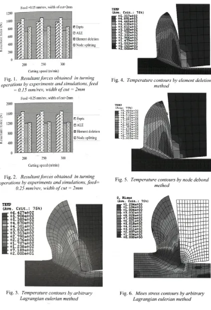
6 RESULTS AND DISCUSSIONS Figs. 1 and 2 outline the resultant forces obtained from the experiments and simulations by ALE and Lagrangian models. The forces obtained by ALE method are in close agreement with the experimental values as compared to the Lagrangian models. The Lagrangian method with element deletion technique under estimates the cutting forces for all the cutting parameters. It can be seen that when machining AISI-H13 with in a speed range o f 200 to 300 m/min cutting forces almost remain constant, which is also confirmed by the simulation results.
Figures 3 to 5 show the temperature distributions obtained by the three methods at cutting speed o f 200 m/min and feed rate o f 0.25 mm/rev. The profiles are significantly different in ALE as compared to both Lagrangian models. In the ALE model temperatures obtained are higher as compared to the Lagrangian models. The shear zone temperatures are in the range o f 250 to 350°C w ith ALE method while 180 to 250°C w ith the Lagrangian methods
The results with Lagrangian methods are also comparable that obtained by N g [4]. Also the high temperature areas are confined to a narrow region in ALE. This m ay be due to the mechanism difference between the two methods. In ALE chip shape is obtained by indentation of the tool into the workpiece while in the Lagrangian method elements are deleted or common sets o f nodes are debonded according to failure criteria as the tool advances. In this way the tool tip carries little or no stress in the Lagrangian methods and hence temperatures are lower. Comparison o f both Lagrangian models
Table 1. Mehanical and physical properties o f workpiece and tool materials
Density kg/m3
Elastic modulus
GPa
Poisson ratio
Thermal Conductivity
W /mK
Specific heat J/kgK
Hardness HRC
W orkpiece 7800 211 0.28 37 560 49
Tool 3399.5 652 0.128 100 960
Cutting speed (m/min)
Fig. 1 • Resultant forces obtained in turning operations by experiments and simulations, feed
= 0.15 mm/rev, width o f cut = 2mm
Cutting speed (nVmin)
Fig. 2. Resultant forces obtained in turning operations by experiments and simulations, feed=
0.25 mm/rev, width o f cut = 2mm
TEMP (Av*. - 45. ■ +4. ■ 44.
44. +3. • +3. • 42 • +2. 41 • 41 - 41 - 46 42
C rit.: ?5*)
.317e402 891*402 .465*402 038e402 .612e402 .185*402 .7S9*402 .332e402 .906*402 .479*402 .053e402 .265*401 .000*401
Fig. 4. Temperature contours by element deletion method
TEMP ( A v g : 7 5%)
+ 5 . 4 0 6 e + 0 2 + 4 . 9 7 2 e + 0 2 + 4 . 5 3 8 e + 0 2 + 4 . 1 0 5 e + 0 2 + 3 . 6 7 l e + 0 2 + 3 . 2 3 7 e + 0 2 + 2 . 8 0 3 e + 0 2 + 2 . 3 6 9 e + 0 2 + 1 . 9 3 5 e + 0 2 + 1 . 5 0 2 e + 0 2 + 1 . 0 6 8 e + 0 2 + 6 . 3 3 8 e + 0 1 + 2 . 0 0 0 e + 0 1
Fig. 5. Temperature contours by node debond method
TEHP (Av*.
g +6.4 2 7 * * 0 2C r i t . : 7S*> .9 0 8 * * 0 2 .3 8 9 * * 0 2 . 870* * 0 2 . 3 51e+ 02 .8 3 2 e+ 02 . 3 13e+ 02 . ?9S e*02 .2 7 6 * * 0 2 . 757*+Q2 .2 3 8 * * 0 2 . 189*+01 . 000e+ 01
Fig. 3. Temperature contours by arbitrary Lagrangian eulerian method
I n s
. C rit.: 7S») 1.204*+03 1.104e+03 L 004*103 9.032e+02 8.028 e+02 ■7.02Se+02 ■6.021 e+02 S. 018 e+02 -4.014e+02 3. Oil e+02 '2.007*+02 1.004e+02 0.000*+00
1 l , -V ! ! liti!
,-l'i ! 1 IMI ■I ' . i 'm ftJW
!5I I i. I ’ .Mi lu ' iM- i I f 1 Fi i 1 ili iü! Il IffW li 1 ' * ! i
ii ;iBiaui!um;iiiWiitsmlln
S, H is e s (Av*. C ric.: 75*1 a r 41.174*403 H - 41,076*403
m - 49.790*402
+8.8146402
47.839*402 4«.864*402 4S.889e402 44,913*402 43.938*402
w 42.963*402 41.988*402 ■ - 41.012*402
■L 43.716*400
Fig. 7. Mises stress contours by element deletion method
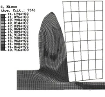
Fig. 8. Mises stress contours by node debond method
show that chip separation is better simulated by node debond method which provides minimum overlapping o f the tool and workpiece. This may be one o f the reason o f higher temperatures with the node debond method.
Figs. 6 to 8 show the M ises stress distributions obtained by ALE and Lagrangian methods at cutting speed o f 200 m/min and feed rate o f 0.25 mm/rev. The stress distributions are quite similar except that the Lagrangian methods show a little lower value o f mises stress. This may be again due to the chip formation technique adopted by the two models. It seems that indentation o f the tool into the workpiece produces greater deformation that results in
higher value o f M ises stress in contrast to the element deletion and node debond methods in the Lagrangian approach. W ith all three models the high mises stress comprises o f the areas including primary shear zone, workpiece area in front of tool tip and the chip tool interface. However the ALE method also shows high M ises stress beneath the flank face (tertiary shear zone) which is in accordance w ith the experimental findings.
7 CONCLUSIONS
1) Cutting forces obtained by ALE and Lagrangian models show that ALE results are in good agreement with the experimental ones. 2) High forces w ith ALE results due to the indentation o f the tool into the workpiece as the model works without any damage criterion. 3) Temperatures profiles are significantly different obtained from the two methods and Lagrangian models show overall lower temperatures.
4) ALE model also show tertiary shear zone which is not found in both Lagrangian models.
8 REFERENCES
[1] Pantale, O., Bacaria, J. L., Dalvemy, O., Rakotomalala, R., Caperaa, S. (2004) 2D and 3D numerical models o f metal cutting with damage effects, Computer Methods in
Applied Mechanics and Engineering 193, p.
4383-4399.
[2] M ovahhedy, M., Gađala, M. S., Altintas, Y.(2004) Simulation o f the orthogonal metal cutting process using an arbitrary Lagrangian-Eulerian finite element method,
Journal o f Material Processing Technology
p. 267-275.
[3] Xie L.J. (2003) Estimation o f two dimensional tool wear based on finite element method PhD dissertation Karlsruhe
University
[4] Ng, E. G., Aspinwall, D. K. (2002) M odelling o f Hard Part M achining, Journal
o f Material Processing Technology 127, p.
222-229.
[5] Xie, J. Q., Bayoumi, A. E., Zbib, H.M. (1997) FEA m odeling and simulation of shear localized chip formation in metal cutting; Journal o f Material Processing