Paper received: 19.3.2007 Paper accepted: 28.9.2007
Using Buckling Analysis to Predict Wrinkling in Incremental
Sheet Metal Forming
Samir Lemeš* - Nermina Zaimović-Uzunović
University o f Zenica, Mechanical Engineering Faculty, Bosnia and Herzegovina
The idea o f using buckling analysis to predict wrinkling o f sheet metal products manufactured by incremental forming is presented in this paper. We start from assumption that buckling analysis can be used to obtain geometry ofproduct after first forming operation. That shape and critical buckling force are calculated using finite element method in elastic domain. The analysis was performedfor various values o f tool diameter. Results were tested through measurement ofproduct geometry after first forming operation. The analysis showed that upper tool diameter can be reduced without change in product quality expressed through number o f wrinkles.
© 2008 Journal o f Mechanical Engineering. All rights reserved.
Keywords: sheet metal forming, incremental forming, buckling, finite element methods
0 INTRODUCTION
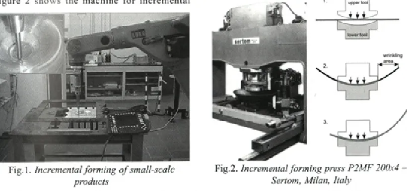
Incremental sheet metal forming is usually being used in small-scale products manufacturing. These products are alw ays m anufactured w ith clamped edges and normally do not have geometrical imperfections related to wrinkling (Fig. 1).
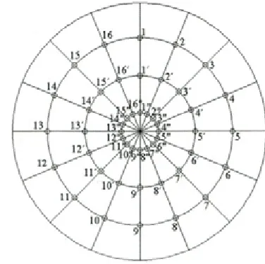
On the contrary, when incremental forming is used to m anufacture large products, such as spherical tank ends, w rinkling phenom ena has significant influence onto quality o f final products. The tool diameter is 2 to 5 times smaller than the forming part diameter, the edge o f forming part is free, and the thickness o f sheet metal plate is small. All these facts contribute to wrinkling occurrence. F ig u re 2 show s the m achine fo r in crem en tal
Fig.l. Incremental forming o f small-scale products
forming o f spherical tank ends up to 4 meters in diameter and sketch o f 3 forming steps. The press uses two-part tool; upper tool is convex, and lower tool is concave, both having the same diameter. Step 3 in Figure 2 is repeated many times in order to incrementally obtain the desired form.
A num ber o f researches were performed recently in order to minimize errors in incremental sh eet m etal fo rm in g . M a c k e rle [1] gave an exhaustive bibliography about application o f finite element method in sheet metal forming simulation. The bibliography deals w ith material properties (texture, anisotropy, and formability), springback, fracture mechanics and calculation strategies, as well as with specific forming processes: bending,
Fig.2. Incremental forming press P2MF 200x4 - Sertom, Milan, Italy
*Corr. Author’s Address: University of Zenica, Mechanical Engineering Faculty, Fakultetska 1, 72000 Zenica, Bosnia
extrusion, deep drawing, pressing, hydroforming etc.
C ao and B oyce [2] used form ing lim it diagram s as a criterion for disproportional tool load regimes. Their research showed that clamping force can be used to influence and to control wrinkling.
W ang and Cao [3] perform ed num erical a n a ly sis o f w rin k lin g u sin g m o d ified energy approach, and investigated sensitivity o f various input param eters and integration methods o f finite elem en t m odel onto buckling prediction. Their m o d e l w as b a se d on a ssu m p tio n th a t stre ss distribution in sheet metal is uniform. By defining appropriate boundary conditions, critical buckling stresses can be determ ined in sense o f m aterial properties, Poisson’s ratio, sheet metal thickness a n d o th e r g e o m e try p a ra m e te rs . W rin k lin g phenom ena w as than analysed by comparing thus obtained critical stress and real compressive stress c a lc u la te d w ith fin ite elem en t m ethod. T h eir research show ed that critical buckling stress o f curved sheet metal depends on:
- local curvature radius, - m aterial properties,
sheet metal thickness, dim ensions and - load.
According to their research, the tool velocity has no influence on wrinkling.
Similar procedure was presented by Wang, Cao and Li [4], applied on bending o f thin walled product edges. They offered an interesting conclusion that wrinkling is reduced when the length o f bent edge is increased. That conclusion could be used to make an assumption: increasing starting sheet diameter could reduce wrinkling o f spherical tank ends. They also investigated the influence o f thickness and concluded that thickness has no influence onto number o f wrinkles, but increased thickness leads to increase in critical length o f bent edge.
Fig.3. Wrinkling o f bent edges o f thin walled products [4]
Pohlak et al. [5] observed this process in rap id prototyping. T hey perform ed num erical calculation in order to optim ize m anufacturing process.
L ee et al. [6] an aly sed the d ifferen ces b etw een static im p lic it and dynam ic e x p lic it integration method in time to compare numerical results in simulation o f cold forming manufacturing process. They divided defects which occur in cold sh e e t m e ta l fo rm in g in to th re e c a te g o rie s : wrinkling, tearing (during deformation phase) and elastic springback (after tool removal).
Schafer and Schraft [7] compared various m ethods o f flexible sheet m etal form ing w ith increm ental deform ation process. Their research was m ore focused on behaviour o f m anipulator ro b o t rath er than o f the m aterial itself. T hey proposed rapid tool movement, such that the tool acts onto sheet metal with strokes.
A m brogio et al. [8] focused on m aterial form ability in increm ental deform ation process, particularly on estim ation and com pensation o f elastic springback. They used integrated numerical/ e x p e rim e n ta l p ro c e d u re to lim it g e o m e try deviations.
Kim and Yang [9] investigated buckling phenomena in deep drawing process using energy principle. They introduced “buckling factor” which is used to predict shape and location o f wrinkles in sheet metal. Figure 4 illustrates wrinkling in deep drawing process.
Similar approach was used in this research. Buckling mode shapes were analysed in order to obtain tool param eters for increm ental form ing process re su ltin g w ith m inim um dim en sio n al deviations o f spherical tank end. The first forming operation, w hen buckling occurs, w as analysed using finite element method.
1 THEORETICAL BACKGROUND
Wrinkling occurs in areas which are not in contact with tool [3]. In incremental forming o f spherical tank-ends, the only two contacts occur betw een the plate and the edge o f lower concave tool, and between the plate and upper convex tool.
T he fo llo w in g a n a ly sis assu m es th at tangential stresses before buckling are neglectable and plate thickness is uniform.
Well known Timoshenko’s energy method w ith various combinations o f boundary conditions was used in analysis o f thin plates elastic buckling. The shape o f deform ed plate is presum ed and critical buckling criterion can be obtained when internal energy o f buckled plate equals the work performed by plane membrane forces. If internal energy for every possible deformation is larger than the w ork performed by membrane forces, the plate is in stable equilibrium.
The process usually starts w ith presumed function which describes plate deformation. It is usually a double sine function, with shape depending on plate shape (circular, rectangular, elliptical, etc.). For circular plate, the function can be:
f ,
w = wosin (« 0 )sin n n (r -r a)
(rr - ra) (1),
\ y
m,n = 1,2,3,...
where w0 is amplitude o f wrinkles, m is number o f wrinkles per perimeter, n is number o f wrinkles in radial direction, r is lower tool radius, r is outer diameter o f the plate.
The following boundary conditions apply:
w = 0, (2)
Fig.5. Incremental forming o f spherical tank end
d 2w 1 dw
2 + V
dr r dr = 0,
r = ra (3).
Equations describing internal energy and work are very complex in this case and it is common to use numerical methods to solve this problem. Analytical calculations, as the one presented in [4], can show what influences critical buckling stress and wrinkling in increm ental forming process. Proposed double-sine function, when visualised, c o rre sp o n d s to m ode sh ap es o b ta in e d by experimental and numerical results presented here. Nevertheless, this function can be used only to confirm the assumption that buckling mode shapes play significant role in wrinkling occurrence during incremental forming.
2 EXPERIMENTAL SET-UP
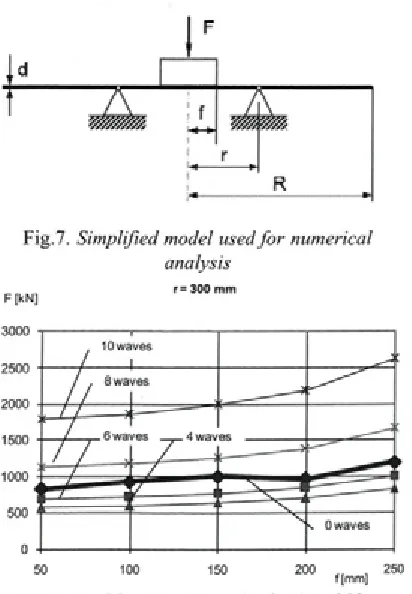
The geom etry o f increm entally form ed spherical tank (Fig. 5) was measured after first forming operation, in order to determine the buckling mode shape. Fig. 6 shows the layout o f measurement points. Some parameters were varied to determine their influence onto buckling mode shape.
The measurement results are shown in Table 1. The number o f lateral waves refers to modal diameters, while number o f radial waves refers to modal circles. The press (Fig. 2) has only indication o f p re ssu re in h y d ra u lic cy lin d e r, w hich corresponds to press force. For deeper analysis, this pressure should be calculated or m easured by means o f force transducers.
Table 1. Geometry measurement results
Pressure [MPal
Lower tool radius [mml
Upper tool curvature radius [mm]
Maximum amplitude [mml
Number of lateral waves
Number of radial waves
a 10 350 700 163 4 0
b 10 350 650 156 6 2
c 10 350 250 136 6 0
d 13 350 250 185 4 0
Table 2. Material chemical composition
C Mn Si P S Al Cu Cr Ni Mo Ti V Nb N
0.17 1.26 0.014 0.015 0.006 0.043 0.03 0.02 0.01 0.002 0.015 0.001 0.039 0.005
The desired buckling mode shape is the one with 0 lateral waves and 1 radial wave. Such a shape can be obtained by changing tool radii or pressure. Finite element analysis was then performed in order to obtain the combination o f tool radius and press force w hich would lead to ideal buckling mode shape after first forming operation.
3 BUCKLING ANALYSIS
The tool radii, as the m ost controllable param eters, were varied in order to estimate their in flu e n c e on to b u c k lin g and w rin k lin g . The
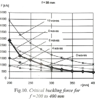
Fig.7. Simplified model used fo r numerical analysis
r= 300 mm F[kN]
simplified model shown in Figure 7 was used. The plate support is circle with radius r (free rotations, fixed translations), the force F acts downwards on the surface with radius f. The plate’s outer radius is R and the thickness is d.
Material used is steel St 52-3 (S355J2G3) with chemical composition given in Table 2. The software used for analysis was UGS I-deas v .ll. To relate the tool radius w ith wrinkling, it was important to sort the results according to buckling mode shapes.
The following values were used: R = 1250 mm d = 12 mm
/ = 50 to 250 mm r - 200 to 600 mm F = 1000 kN
3.1 The influence of upper tool radius
The linear buckling analysis was performed for set o f upper tool radii. Figure 8 shows analysis results for lower tool radius r=300 mm and variable upper tool radius f sorted according to num ber o f waves.
r= 400 mm F [kN]
f = 50 mm F[kN]
f =200 to 400 mm
It is evident from Figure 8 that number o f wrinkles does not change significantly with change in upper tool radius f
The analysis perform ed w ith low er tool radius r=400 mm and variable upper tool radius / showed even smaller influence o f upper tool radius / onto critical buckling force (Fig. 9).
3.2 The Influence of Lower Tool Radius
A n o th er an aly sis w as th en perfo rm ed , varying the low er tool radius r values, keeping u p p er tool radius /= 5 0 mm constant. Figure 10 shows that increase in lower tool radius reduces critical buckling force.
S in ce r e s u lts p re s e n te d in F ig u re 10 show ed increased influence o f low er tool radius, s im ila r a n a ly sis w as p e rfo rm e d w ith la rg e r
i l g . i z , . iv iu u e ò n u jje ò w iin *t, u, o u n u l u w uveò
f = 150 mm F[kN]
f= 2 0 0 to 400 mm
upper tool radius and variable low er tool radius. Figure 11 show s analysis results for upper tool radius ./=150 mm.
3.3 Buckling Mode Shapes
The mode shapes which were used to sort the FEM analysis results are shown in Figure 12. The number o f waves can be controlled with press force; the critical buckling force determines the buckling mode shape.
It is desirable to control m anufacturing parameters in such a way that buckling mode shape shown in Figure 13 occurs. The analysis performed here showed that tool radius and press force can be used to change the mode shape, but it is rather hard to obtain desired shape, because different mode shapes have overlapping curves.
F in ite elem ent m ethod uses solution o f eigenvalue problem to calculate both buckling and v ib ratio n m ode shapes. In m athem atical term s, every solver algorithm gives results sorted by size. It is im portant to visualise all numerical results, to be able to determine number o f waves (wrinkles) from FEM results. For example, FEM solver gives 10 m ode shapes accompanied with 10 critical force values, and visualisation must follow to determine the num ber o f waves for each critical force value.
3.4 Experimental Results
To check the validity o f numerical results, the geom etry o f increm entally formed spherical tank w as measured after first forming operation. As num erical results led to conclusion that upper to o l rad iu s has low influence onto num ber o f w rinkles, the m easurem ents were perform ed for th re e d iffe re n t cu rv atu re rad ii o f u p p e r tool, betw een 250 and 700 mm. As Figure 14 shows, the larger curvature radius, the larger contact surface b e tw e e n u pper tool and the sheet m etal being form ed.
According to results presented in Table 1, sig n ifican t decrease in upper tool radius led to neglectable change in number o f waves (wrinkles), as o p p o se d to p re ss fo rce, w h ich has stro n g influence onto buckling mode shape, in terms o f both num ber o f waves and buckling amplitude.
T h erefo re, both FEM and experim ental a n a ly s is sh o w e d th a t u p p e r to o l ra d iu s has neglectable influence onto buckling mode shapes a n d n u m b e r o f w rin k le s a fte r fir s t fo rm in g operation.
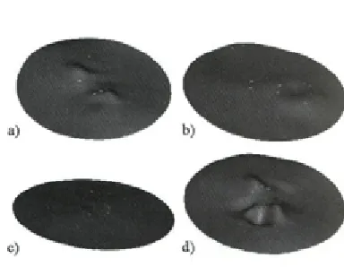
F igure 15 shows m ode shapes m odelled according to measurement results. The captions a, b, c, d correspond to m ode shapes presented in Table 1.
n < r 2
Fig. 14. Relation between curvature radius and contact surface
4 CONCLUSIONS
Linear elastic finite element analysis was used in this research in order to obtain buckling mode shapes for various radii o f upper and lower tool. The analysis showed that number o f wrinkles, which corresponds to number o f waves in buckling mode shape, cannot be easily controlled by means o f tool radius. The curve corresponding to zero- wave m ode shape (the shape w ithout wrinkles) propagates over entire domain and intersects other curves, as shown in Figures 8 to 11.
However, the upper tool radius is proven to have less influence onto critical buckling force and number o f waves. That means the upper tool could be kept sm aller, thus reducing the tool costs, keeping product quality the same.
It is hard to control process parameters to provide conditions w hen desirable mode shape occurs. The press force should be controllable if one wants to influence the buckling mode shape.
It is shown that conclusion given in [4] is not applicable in cases w ith free, unclamped edges.
Thin sheets wrinkle more easily and due to large lateral deformation. In contrary, thick plates w rinkle w hen deform ation is lim ited; buckling occurs when major stress is compressive. In this manufacturing process upper surface is compressed and it buckles in a predictable mode shape. The higher mode shapes calculated by FEM correspond to wrinkles measured experimentally.
The major lack o f this research is inability to control press force precisely, which is limitation introduced by press design. Further experiments should be perform ed on press with controllable force.
5 REFERENCES
[1] M ackerle, J. F inite elem ent analyses and simulations o f sheet metal forming processes. Engineering Computations, Voi. 21 (2004) No. 8, p. 891-940.
[2] Cao, J., Boyce, M.C. A Predictive Tool for Delaying W rinkling and Tearing Failures in Sheet M etal Form ing. Transactions o f the ASME, Vol. 119 (1997), p. 354-365.
[3] Wang, X., Cao, J. On the prediction o f side- w a ll w rin k lin g in sh e e t m e ta l fo rm in g p ro c e sse s. In tern a tio n a l Journal o f Mechanical Sciences, 42 (2000), p. 2369-2394. [4] Wang, X., Cao, J., Li, M. Wrinkling analysis
in shrink flanging. Transactions o f the ASME, Vol. 123 (2001), p. 426-432.
[5] Pohlak, M., Küttner, R., Majak, J. Modelling and optim al design o f sheet m etal RP&M processes. Rapid Prototyping Journal, 11/5 (2005), p. 304-311.
[6] Lee, S.W., Yoon, J.W., Yang, D.Y. Comparative investigation into the dynamic explicit and the static implicit method for springback o f sheet metal stamping. Engineering Computations, Voi. 16 (1999), No. 3, p. 347-373.
[7] Schafer, T., Schraft, R.D. Incremental sheet m etal form ing by industrial robots, Rapid Prototyping Journal, 11/5 (2005), p. 278- 286.
[8] Ambrogio, G., Costantino, L, De Napoli, L., F ilic e , L ., F ra tin i, L ., M u zzu p ap p a, M. In flu e n c e o f som e re le v a n t p ro c e ss param eters on the dim ensional accuracy in in c re m e n ta l fo rm in g : a n u m e ric a l and e x p e rim e n ta l in v e s tig a tio n . Jou rn a l o f Materials Processing Technology, 153-154 (2004), p. 501-507.