International Doctorate School in Information and Communication Technologies
DISI - University of Trento
Design and Analysis of Load-Balancing Switch
with Finite Buffers and Variable Size Packets
Yury Audzevich
Advisor:
Prof. Yoram Ofek
Universit`a degli Studi di Trento
Co-Advisor:
Prof. Renato Lo Cigno
Universit`a degli Studi di Trento
Abstract
As the traffic volume on the Internet increases exponentially, so does the demand for fast switching of packets between asynchronous high-speed routers. Although the optical fiber can provide an extremely high capacity, the Internet switches still remain the main point of traffic bottleneck. The packet switching time may run up to nanoseconds in such routers with more than thousands ports, each processing at 10 GB/s. Even modern extremely fast processing units are not capable to satisfy these needs. It is well known that switching of such a high volume of traffic from input to output requires large buffers and fast processors to perform the header processing, complex scheduling and forwarding functions. Although a large number of switching architectures is presented on the market, the considerable part of them is either not scalable or reach their limits in power consumption and complexity. Therefore, novel and extremely scalable switching systems are essential to be investigated. The load-balancing switching approach is simple, and therefore, may be capable of per-forming the switching and forwarding from all inputs to all outputs simultaneously with low complexity and high scalability. Since this simple approach has distributed topology (each component of the switch is controlled by an individual chip) and do not require fast switch control units, primarily because each stage is independent and it makes its own dis-tributed calculations, it becomes a perfect candidate for the future practical deployment. The load-balancing switching architecture, considered in this thesis, is proved to have high potential to scale up while maintaining good throughput and other performance charac-teristics. Additionally, the load-balancing switching architecture can effectively resolve the important problem of packets mis-ordering which can appear due to the distributed structure of the system. Unfortunately, in the research conducted previously, some of the mentioned characteristics were obtained under a set of strong assumptions. In particu-lar, it was assumed that all the packets transmitted through the system have equal length, traffic is admissible and central stage buffers are infinite. On the other hand, due to the distributed control the switch is not able to control and maintain a necessary amount of traffic transmitted from stage to stage inside the switch.
switch performance if inputs of the switch are overloaded.
In order to present more realistic scenario, the packet loss analysis was performed in the switch with variable size packets. It is considered that most of the internet switches are operating on the cell-based level (to increase buffer utilization), that means that arriving variable size packets are segmented at inputs and reassembled at outputs. The issue of possible cell and correspondingly a packet loss inside the switch can introduce some signif-icant posterior problems to the load-balancing switch reassembly unit. In order to evaluate packet loss we assumed Markovian behavior to be able to use numerically efficient algo-rithms to solve the model. The mathematical model characterizing inhomogeneous input traffic presented inside the thesis gives the most precise way of packet loss probability evaluation. Unfortunately, the high complexity of this model results in irresolvably com-plex Markov chains even in case of very small switches. Consequently, as a next step, we performed the analysis with fast solution procedures using a restrictive assumption of identical stochastic processes at all inputs. The final results allowed us to conclude that a single cell drop at the central stage buffers cause the whole packet removal and, the packet loss probability inside the system can be extremely high in comparison with the cor-responding cell loss. Another important issue observed from the analysis is the difference in packet loss probabilities depending on the traffic traversing path, e.g. sequential number of input, central stage buffer and output of the switch. This property makes more complex the evaluation of the loss probabilities for large switch sizes. The last but not the least issue observed by our analysis was the instability, congestion and large delays appearing at output re-sequencing and reassembly unit due to the the central stage packet loss.
Acknowledgments
I am extremely grateful to my advisor Prof. Yoram Ofek for his incredible wisdom, immense knowledge, motivation and enthusiasm provided during my Ph.D. study in Italy. His guidance helped me in all the time of research, and his continuous support encourage me not only in professional but also in moral respect. I could not have imagined having a better advisor for my Ph.D. study.
Besides my advisor i would like to thank to my co-advisor Prof. Renato Lo Cigno, for his relentless support, supervision, advices and his continuous involvement into my research activities and assistance in resolution of non-scientific concerns. I am grateful in every possible way and hope to keep our collaboration in the future.
Many sincere thanks go in particular to Prof. Mikl´os Telek for his continuous help and guidance. I am really grateful to him for the offered opportunity of visiting and working with the members of the Stochastic Modelling lab at the Technical University of Budapest. Both Prof. Mikl´os Telek and all the members of his group have created inexhaustibly energizing, motivating and supportive atmosphere in the lab. My special thanks are dedicated to my friend and colleague Levente Bodrog for sharing his experience with me in stochastic modelling, his productive discussions and readiness to help.
Finally, i would like to express my sincere gratitude to Prof. B˝ulent Yener without whom the investigations on the topic of this thesis might not even have been initiated. His experience, wise advices and assurance of success have enlightened me in the first glance of the research in the load-balancing switching field.
For all good time and support during my Ph.D. years I am grateful to my colleagues and friends, especially to: Danilo, Vladimir, Dmitry, Olga, Nikolay, Ivan, Andrey, Raman, Thang, Huong and Marcin.
Last but not the least, I would like to thank my family for their invaluable help and support: my parents, and my wife Tatsiana.
This work is dedicated...
This work has been developed in collaboration with various people and in particular with: Yoram Ofek, Renato Lo Cigno, Mikl´os Telek, B˝ulent Yener, Levente Bodrog, Danilo Severina, and Giorgio Fontana.
This thesis makes the following contributions:
• Presents an overview of the currently deployed switching technologies on the market;
• Reviews the scalability limitations of the load-balancing switching architectures;
• Performs analysis of the load-balancing switching architectures with fixed and vari-able size packets;
• Presents mathematical models and simulator for the packet loss evaluation inside the switch;
• Proposes design and analysis of protocols which minimize/avoid the central stage packet loss of the load-balancing switch;
Part of the material of the thesis has been published (to appear) in various conferences, journals and technical reports (in order of appearance):
• [69]: Y.Audzevich, Y. Ofek, M. Telek and B. Yener. Analysis of Load-Balanced Switch with Finite Buffers. In IEEE GLOBECOM’ 08, Dec. 2008.
• [6]: Y. Audzevich and Y. Ofek. Assessment and Open-issues of the Load-balanced Switching Architecture. In IEEE FGCN’08, Dec. 2008.
• [4]: Y. Audzevich, L. Bodrog, M. Telek, Y. Ofek, and B. Yener. Variable Size Packets Analysis in Load-Balanced Switch with Finite Buffers. In Technical report, TU Budapest, Apr 2009.
• [5]: Y. Audzevich, M. Corra, G. Fontana, Y. Ofek and D. Severina. Energy Efficient All-Optical SOA Switch for the Green Internet. In FOTONICA’09, May 2009.
• [3]: Y. Audzevich, L. Bodrog, Y. Ofek and M. Telek. Scalable model for packet loss analysis of Load-Balancing switches with identical input processes. In IEEE
Load-Balancing Switch with ON/OFF Input Processes. In EPEW’09, Jul 2009.
• Y. Audzevich and Y. Ofek. Overview and Evaluation of Load-Balancing Switches. Submitted to Computer Networks Journal.
• Y. Audzevich, L. Bodrog, Y. Ofek and M. Telek. Packet Loss Minimization in Load-Balancing Switch. Submitted to IEEE ASMTA ’10.
• Y. Audzevich, G. De Blasio, R. Lo Cigno, M. G. Frecassetti, F. Granelli and D. Kliazovich. SoPSim: Simulation of Circuit Emulation over Packet for Microwave Radio Links. Submitted to IEEE EuWiT ’10.
Contents
1 Introduction 1
1.1 The Context . . . 1
1.2 Problems, Solutions and Thesis Structure . . . 3
2 State of the Art and Related work 5 2.1 Classification of Switching Architectures . . . 7
2.1.1 Distributed designs with fix routes . . . 8
2.1.2 Distributed designs with non-deterministic routes . . . 10
2.1.3 Time-Driven switching . . . 12
2.2 The Load-Balancing Switching Architecture . . . 12
2.2.1 The architecture, assumptions and open issues . . . 13
2.3 LB Switch Designs Preventing Cells Mis-Sequencing . . . 17
2.3.1 Uniform frame spreading . . . 17
2.3.2 Padded frame algorithms . . . 18
2.3.3 The mailbox switch . . . 18
2.3.4 The Contention and Reservation switch . . . 20
2.3.5 The Concurrent Matching switch . . . 21
2.3.6 Re-sequencing in the multi-stage buffering scheme . . . 22
2.3.7 Byte-Focal switch . . . 23
2.4 Evaluation of the System’s Scalability in Space and Time . . . 24
2.4.1 Scalability limitations regarding the basic scheme . . . 24
2.4.2 Scalability of recent architectures, computation and communication overhead . . . 25
3 Scientific Questions 35 3.1 The Considered Open Issues . . . 36
3.1.1 Cell and packet loss . . . 36
3.1.2 Ways to avoid packet loss . . . 38
3.1.3 Re-sequencing and reassembly . . . 39
4.2 Assumption and Traffic Model . . . 42
4.3 The Packet Loss Analysis: 2 x 2 LBS case . . . 43
4.4 The Packet Loss Analysis: N x N LBS case . . . 46
4.5 Computational Results and Summary . . . 51
4.5.1 Numerical and simulation model . . . 51
4.5.2 Results and interpretations . . . 52
5 The LBS with Variable Size Packets 57 5.1 The Considered Load-Balancing Switching Architecture . . . 59
5.2 The General Case Packet Loss Analysis . . . 60
5.2.1 Properties of the different paths . . . 61
5.2.2 The cell level model . . . 62
5.2.3 The packet level model . . . 65
5.2.4 The probabilities of packet loss and successful packet transmission . 69 5.2.5 Analysis of N ×N load-balancing switch . . . 72
5.3 The O(2N) Complexity Packet Loss Analysis . . . 73
5.3.1 Input model . . . 73
5.3.2 The cell level model . . . 76
5.3.3 The packet level model . . . 78
5.4 The Linear Complexity Packet Loss Analysis . . . 82
5.4.1 The model of the input processes . . . 82
5.4.2 Aggregate input model . . . 85
5.4.3 The cell level model of the 3×3 switch . . . 86
5.4.4 The packet level model . . . 86
5.4.5 On the solution of large QBD-like DTMCs . . . 89
5.5 Experimental Results and Summary . . . 90
5.5.1 Computation study: general case . . . 90
5.5.2 Computation study: 2N complexity case . . . 93
5.5.3 Computation study: N + 1 complexity case . . . 94
5.5.4 Additional simulation results . . . 97
5.5.5 Summary . . . 104
6 Packet Loss Minimization and Avoidance 107 6.1 Protocol for Packet Loss Minimization . . . 108
6.1.1 The Implementation . . . 108
6.1.2 Information exchange in the controller . . . 111
6.1.5 Differences in the cell level model . . . 115
6.1.6 The packet level model . . . 115
6.1.7 The initial distribution of the packet level model . . . 116
6.1.8 The minimal loss probability of the system . . . 117
6.1.9 Experimental results . . . 117
6.1.10 Summary . . . 120
6.2 NoLoss Load-Balancing Switch . . . 120
6.2.1 The architecture . . . 122
6.2.2 Experimental results . . . 129
6.2.3 Summary . . . 133
7 Conclusion 135 7.1 Summary . . . 136
7.2 Future Work . . . 136
Bibliography 139
List of Tables
2.1 Potentially scalable switching architectures . . . 8
4.1 LB switch occupancy during three time slots . . . 44
4.2 Possible variation of the function values versus arrival probabilities . . . . 45
5.1 The three possible settings of 3×3 LB switch . . . 60
5.2 The possible time evolution of input 1 with packet arrival . . . 71
5.3 Parameters used for the numerical studies . . . 91
5.4 The main parameters of the computation . . . 93
5.5 Parameters used for the numerical studies . . . 95
5.6 Parameters used for simulations of Part 1 . . . 99
5.7 Parameters used for simulations of Part 2 . . . 102
5.8 Parameters of used Pareto distribution . . . 103
5.9 Packet delay grows analyzed in Figure 5.30 . . . 104
6.1 Total system overheads for various implementation schemes . . . 114
6.2 Parameters used for the numerical studies . . . 117
List of Figures
2.1 Parallel Iterative Matching: one iteration . . . 9
2.2 Representation of iSLIP matching algorithm . . . 9
2.3 The basic LB switch . . . 10
2.4 Tree embedded ring; short-cut (V N2−V N4) and jump (C−G) . . . 11
2.5 Use of single input buffer switch for Hot-potato, MSN and MetaNet routing 12 2.6 LB switch with single-stage buffering . . . 13
2.7 The Mailbox switching architecture [15] . . . 19
2.8 Example of symmetric interconnection pattern [15] . . . 19
2.9 The Contention and Reservation switch [75] . . . 20
2.10 The Concurrent Matching switch [46] . . . 21
2.11 LB switch with multi-stage buffering [18] . . . 22
2.12 The Byte-Focal switch [57] . . . 23
2.13 The Frame-Aggregated CM switching architecture [47] . . . 30
2.14 Staggered symmetry interconnection pattern for N = 3 [73] . . . 32
3.1 The considered LB switching architecture . . . 36
4.1 Single-stage buffering LB switch . . . 42
4.2 2 x 2 LB switch . . . 44
4.3 State-transition diagram for 2x2 LB switch with central buffer of size B = 4 45 4.4 N x N LB switch with finite buffers . . . 47
4.5 Possible transitions of N×N LB switch when B > i−1 +N . . . 48
4.6 The transition graph of LB switch with N = 3 and B = 5. . . 50
4.7 The transition probability matrixQ . . . 50
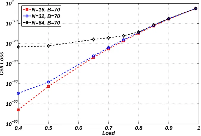
4.8 Cell loss versus load (ρ= 0.4. . .0.99) for N x N LB switch, buffer=70 cells, admissible uniform i.i.d traffic. . . 52
4.9 System loss versus load for N x N LB switch, overall load range ρ = 0.9. . .1.99, buffer = 70 cells, inadmissible traffic. . . 53
4.13 Buffer size versus switch size with loss probability 1E−12 and 1E−09,
for overall load of 0.99 (admissible uniform i.i.d traffic). . . 55
5.1 The considered LB switch . . . 59
5.2 The DTMC modeling input i . . . 63
5.3 The transient DTMC for packet level model . . . 66
5.4 The revised DTMC model of input 1 . . . 67
5.5 The DTMC of input 1; a new packet arrival . . . 71
5.6 The DTMC which fully characterizes input 1 of 3×3 LB switch . . . 74
5.7 The DPH substitution of off states for a pair with input 1 - output 0 . . . 75
5.8 The ON/OFF DTMC describing a pair with input i- output j . . . 76
5.9 The transient DTMC which characterizes a VOQ during a life cycle of a packet . . . 78
5.10 The modified graphs of the ON/OFF DTMC describing input 1 . . . 80
5.11 The DTMC which characterizes every input of 3×3 LB switch . . . 83
5.12 The DPH substitution of off states in terms of output 0 . . . 84
5.13 ON/OFF model of the input process with a simplified notation . . . 85
5.14 Packet loss as a function of buffer size; comparison between analysis and simulations . . . 91
5.15 Packet/cell loss of a specified path as a function of idle period . . . 92
5.16 Packet loss probability versus buffer size (study 1) . . . 94
5.17 Packet loss probability versus switch size (study 2) . . . 94
5.18 Packet loss versus buffer size . . . 95
5.19 Packet loss versus switch size . . . 96
5.20 Packet waiting time versus buffer size . . . 96
5.21 Packet waiting time versus switch size . . . 97
5.22 Packet loss as a function of buffer size . . . 97
5.23 Packet waiting time versus buffer size . . . 98
5.24 Dependence of the overall packet loss, packet loss on a path and cell loss versus buffer size . . . 99
5.25 Dependence of the overall packet loss, packet loss on a path and cell loss versus switch size . . . 100
5.26 Dependence of packet loss inside a path over buffer size . . . 100
5.27 Dependence of average packet traversing delay at the second stage versus switch size . . . 101
rival period 4 cells . . . 103
5.30 Dependence of packet reassembly delay on buffer size . . . 104
6.1 The considered LB switch . . . 109
6.2 Timing diagram . . . 111
6.3 Information processing and exchange at the centralized controller . . . 112
6.4 Analytical and simulations representation of joint packet loss probability versus threshold . . . 118
6.5 Dependence of joint packet loss probability versus threshold for various switch sizes . . . 118
6.6 Joint packet loss probability versus switch size . . . 119
6.7 Joint packet loss probability as a function of protocol threshold . . . 120
6.8 The NoLoss LB switching architecture . . . 122
6.9 Example of 4×4 NoLoss LB switch . . . 125
6.10 Sequence of controller operations during a time slot . . . 129
6.11 Dependence of joint packet loss as function of buffer size . . . 130
6.12 Joint packet loss dependence versus switch size . . . 131
Introduction
According to the latest statistics, the amount of users connected to the Internet is growing extremely fast every year. For instance, the World Internet Usage Statistics organization reports that during the period from 1992, when Internet was pulled to the general public, up to the present time the number of Internet users became 100 times larger. In addition to that, demand on the ”bandwidth-hungry” applications is increasing every year. Various types of applications represented in the modern network cover all the aspects of human life. In particular, the network resources are widely used in business, science, and mostly at entertainment. The number of internet users can be easily divided in both the regard to the time spent online and the amount/type of applications they use. Technological developments in both the electronics and telecommunications have extended broadband capacity of private networks from a limited ”Internet browsing” function to a fundamental entertainment capabilities while exploring services such as Video-on-Demand and IPTV.
1.1
The Context
In order to provide the increasing demand to the network resources novel technologies for realization of transmission medium as well as for the Internet routing are introduced.
attractive. In such a system, the packet scheduling decision is achieved by a separate block which is independent from all other system’s blocks. Although the on-chip control is not always considered to be simple, it gives the possibility to easily scale up the system without significant drop in performance.
In this thesis we focus on the representation of the various switching/routing architec-tures based on the distributed control. The initial part of this thesis, e.g. chapter 2, will show the technologies used for a scalable switch/router implementation. The main task of each network router can be simply reduced to routing and forwarding of incoming in-formation. It is considered that a router is operating in both control plane (the process of the most optimal interconnection decision is performed) and forwarding plane (where the information is actually sent). However, it is possible that due to internal router topology, the complete routing decision cannot be specified at the control plane at once. This rule is mostly related to the routers implementing non-deterministic or adaptive forwarding. In contrast to the assignment of a fixed traversing route, such routers can dynamically decide which hop(s) is(are) more preferable for optimal information forwarding. The main drawback of routers with non-deterministic routing can be the capacity expensive commu-nication overheads, which in some cases can be even larger than the amount of information transmitted. Additionally, such routers are a subject of extremely large traversing delays and low throughput.
In contrast, the forwarding decision which is performed in distributed routers with deterministic management can be specified after a decision making phase. The load-balancing (LB) switch can be attributed to such a category of routers. It was firstly presented in [16, 17, 40] where it is implementing extremely simple ingress-egress inter-connection scheme, realized in round-robin run of crossbars. In general LB switch is composed of three stages, each of the stages contains a certain amount of buffering. The interconnection between the stages is performed by means of crossbar switches which are synchronized to the rest of the system. Due to the fact that decision about packet forward-ing is deterministic at each time point, the system does not use any additional overheads for the forwarding decision phase. All these features deploy both extremely high scala-bility and good performance characteristics of the LB switch. All the positive features as well as novelty of the proposed approach makes the LB switch the main focusing point of this thesis.
in [15, 40, 46, 57, 75]. It is important to mention that some of the architectures to resolve packets mis-sequencing require extra control, introducing different overheads (commu-nication and computational), that basically increases the control complexity of the LB switch. However, keeping correct sequence of packets through the system avoids unnec-essary retransmissions of packets in the network protocol layer [10].
1.2
Problems, Solutions and Thesis Structure
The initially considered set of assumptions makes impossible to analyze the LB switch behavior under conditions existing in the real Internet router [23]. In particular the maximum system’s throughput (100%) can be reached only in the ideal case with infinite central stage buffers. Taking into account the fact that practical networking devices will always have a limited space for packet storage and forwarding, in the future we perform analysis only for LB switches with finite amount of buffering (Chapter 3).
The first attempt to analyze (by means of simulations) the central stage packet loss was performed in [65]. In contrast to this work we propose in [69] a novel mathematical model, which allows to evaluate central stage packet loss for any set of parameters N
removal.
In addition to the mathematical model, as a tool to better understand and optimize performance and/or reliability of the LB switch, the LB switch simulator was also exten-sively used. In contrast to the modelling, the simulation tool allowed to explore obtained results and get understanding of the future behavior of the system when conditions close to real, e.g. heavy-tailed traffic matrices or limited amount of buffering at the output, are applied (like it is presented in section 5.5.4).
In addition to the problem of cell and packet loss at the central stage buffers, the analysis reveals a set of novel issues related to the re-sequencing and reassembly units (RRU). In particular, the amount of memory resources at RRU that can be held by congested data cells is expanding with increase of the central stage packet loss. Due to the fact that the LB switch does not perform any control on the traffic transmitted form a stage to another one, the data cells of incomplete packets (dropped at the central stage) arrive to outputs and should be handled by the processor of RRU. As a result of such unreliable packet transmissions a certain number of memory locations in the buffer is wasted by the cells of incomplete packets waiting for reassembly.
State of the Art and Related work
solutions capable to provide good performance characteristics in real networks.
To start the discussion we refer to output buffer switches [36], which, at the moment are not of the great interest from the scalability prospectives. In spite of the fact, that switch is able to provide guaranteed throughput, the use of large memory speedup makes it non realizable for more than hundred of ports. Completely another interest is raised by input buffer switches where some scheduling decision algorithms are performed. To eliminate head-of-line blocking in the inputs, buffers with random access and virtual output queuing [36] structures get under the way. Apparently, input buffer switch requires scheduling algorithm in order to match and interconnect inputs with outputs. It is well known that both centralize controller or a distributed management schemes can be used to resolve ingress-egress matching problem. As our interest is given mostly to distributed-control algorithms (e.g. operating on per-port basis), next, we will present two particular implementations on the example of Parallel Iterative Matching (PIM) [62] and iSLIP [49] algorithms. We concentrate our attention on the input buffer switch defining two main implementation branches. The input buffer switches with fix routing schemes (like PIM and iSLIP) will be described first. However, the significant interest will be given also to representation of schemes with non-deterministic packet routing like presented in [8, 48, 54, 55].
As a completely different approach, the Time-driven switching (TDS) [7] deploys pipeline forwarding inside the network using global common time reference. Thanks to coordinated universal time, all the switches in the network are synchronized and use negligible amount of buffering for packet transmission. TDS scheduler reserves transmis-sion resources for a dataflow in advance, thus allowing packet header processing to be excluded.
the proposed designs. In addition, we introduce a novel problem of cell/packet loss inside the switch. This issue has strong dependency on the system stability and its performance.
2.1
Classification of Switching Architectures
By definition, a network switch is considered to be a device that performs transparent ingress-egress bridging at up to speeds of a hardware. Topologically each switch can be viewed as a network located in a box. All the systems making internal switching can be further classified as input or output buffered depending upon the position of buffers. As it was mentioned before, our main requirements are to find switching architectures being capable of scaling up to at least of thousands ports and support of minimum 10 Gb/s per port rate.
Although a switch using output queuing has better throughput and delay performance characteristics than switches using input queuing, the hardware costs can be enormous for large output buffer switches. Moreover, output buffer switches are fairly complex and require large speedups of transmission buffers due to simultaneous arrival of more than one input packet for the same output [36]. On the other hand, it has been also shown that the throughput of a switch with input queuing is only 0.586 of the full capacity. The main reason of this poor throughput is due to head of line (HOL) blocking where packets at the head of input queues contend for the same output while the packets destined for free outputs are waiting in a line. Due to the implementation simplicity and total costs, it is still feasible to build large switches using input buffering techniques. Some ingenious solutions were proposed to solve HOL blocking problem [50].
In particular, instead of using first-in-first-out (FIFO) policy in each input the vir-tual output queuing (VOQ) scheme creates per output queues at each input. In such a way each packet occupies a virtual queue corresponding to the output, and none of the packets are blocked. Moreover, input buffer switch requires common scheduler. In practice, scheduler’s complexity is in the strict relation with the system performance. Henceforward, our attention will be dedicated to algorithms distributing decision com-plexity among the ports, allowing the neglect of centralized control for an input buffered switch. In the following sections we will represent also the load-balancing [17, 18, 40] and Time-Driven [7] switching principles. In the upshot, some relevant to this thesis archi-tectures, like Metaring [21] and MetaNet [54, 55] and, switching architectures build upon Combinatorial Designs [71, 72], will be depicted. Table 2.1 presents the classification of the most space-time scalability appropriate solutions in the research.
Time
Space
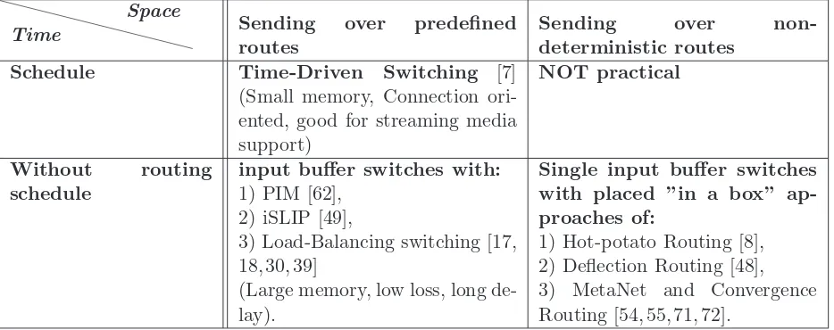
Sending over predefined routes
Sending over non-deterministic routes
Schedule Time-Driven Switching [7] (Small memory, Connection ori-ented, good for streaming media support)
NOT practical
Without routing schedule
input buffer switches with:
1) PIM [62], 2) iSLIP [49],
3) Load-Balancing switching [17, 18, 30, 39]
(Large memory, low loss, long de-lay).
Single input buffer switches with placed ”in a box” ap-proaches of:
1) Hot-potato Routing [8], 2) Deflection Routing [48], 3) MetaNet and Convergence Routing [54, 55, 71, 72].
Table 2.1: Potentially scalable switching architectures
A packet transferring with predefined route can be possible in the routers with schedulers or in the systems where predefined configuration is applicable. On the other hand, the architectures where packet traverses along a non-deterministic route can be present. De-flection routing [48] and MetaNet Convergence routing [54, 55], if to be positioned ”in a box”, can be a good example of a non-deterministic routing. Figure 2.5 shows the use of Hot-potato routing [8] and all the other non-deterministic routing-schemes located into a single input buffer router. Table 2.1 strictly differentiates and underline importance of these two routing approaches.
2.1.1 Distributed designs with fix routes
Parallel Iterative Matching [62]. The following matching algorithm was implemented in Input buffering switch, using memory with random access [62]. The algorithm finds conflict-free pairing of inputs to outputs, only for pairs with a queued cell to transmit between them. Parallel iterative matching uses parallelism, randomness, and iteration to accomplish matching efficiently. The operational steps during one iteration are the following (Figure 2.1). First unmatched input sends request to every output for which it has buffered cell. If unmatched output receives any request, it chooses one randomly to grant. The outputs notify each input whether its request was granted. Finally if an input receives some grants, it chooses one to accept and notifies that output. It’s possible that some inputs and outputs remain unmatched. In this case the algorithm runs another iteration excluding operations with previously matched inputs. The explicit schedule is built for each input-output pairings for each slot in a frame. Scheduler can be extended to allocate resources fairly when network is overloaded. Finally, distributed calculations make the system scalable.
1 2
2 4
4
Request Grant Accept
Figure 2.1: Parallel Iterative Matching: one iteration
rotating priority (”round-robin”) arbitration to schedule each active input and output. This fact improves performance, so for uniform traffic in can achieve 100% throughput with single iteration. In fact iSLIP is similar to round-robin matching algorithm with the difference that its not moving grant pointers unless grant is accepted. The operational idea is represented in Figure 2.2. It was found in [49] that forN×N switch it takes about
log2N iterations to converge. It has high throughput for uniform traffic. The algorithm is simple and for small switches arbiter can be placed on a single switch. For N > 1000 ports switch will have large computation overhead, and might not be highly scalable.
Figure 2.2: Representation of iSLIP matching algorithm
Figure 2.3: The basic LB switch
slotted. This implies that the only one cell can arrive and depart switch during the time slot. Finally each linecard is able to support strictly equal rate flows.
The operational idea behind the distributedN×N size architecture is to load-balance or spread uniformly the cells from the input along the VOQs of central buffering stage. Since every component is synchronized, input crossbar periodically interconnect each in-put to independent buffering units at the central stage. There, the cells positioned in the corresponding to the output port number VOQ. Later on, the VOQ will be served by the second crossbar switch to the output. Input and output crossbars configured simi-larly with the periodic round-robin connection pattern, linking input, central and output stages. The configuration is not based in the occupancy of the queues, both switching stages walk through a fixed sequence of configurations.
The basic LB switch is promised to be highly scalable. Due to predefined properties it should have a 100% throughput for a broad class of arrival admissible traffic (any traffic distributed uniformly between outputs) even without centralized scheduler. The basic scheme also promises to provide a low average delay even under heavy load and bursty traffic (mathematical representation can be found in [17, 18]). Absence of centralized control mechanism greatly reducing hardware complexity of the switch which makes it easier to implement. Therefore, this architecture was considered as a main candidate for our detailed investigation for the future.
2.1.2 Distributed designs with non-deterministic routes
The spatial reuse provides the ability to concurrently transmit over distinct segments of the ring. Hardware control signals are used to enable independent control functions in the network. Packets in the MetaNet can make short-cuts toward it destination (see Figure 2.4) in order to decrease routing distance. Another possibility is to make jumps on threads. Due to dynamic convergence routing MetaNet has no packet loss and capable of supporting real time traffic.
Figure 2.4: Tree embedded ring; short-cut (V N2−V N4) and jump (C−G)
Manhattan street network [48]. The Manhattan Street Network (MSN) [48] is a self-routing regular topology, originally proposed for local and metropolitan area network applications. An MSN is characterized as a two-connected regular mesh with the nodes connected as rows and columns. Each node consists of a 2× 2 crossbar switch that connects incoming links to outgoing links. The Clockwork Routing Scheme is a time-slotted system that enhances the MSN. It’s includes a simple routing mechanism employed at intermediate nodes that prevents resource contentions, requires no re-sequencing of packets at the destination node and has comparable throughput to conventional routing schemes.
Switch Controller
NO BUFFERS
Usually non-blocking switch fabric (e.g. crossbar)
Figure 2.5: Use of single input buffer switch for Hot-potato, MSN and MetaNet routing
2.1.3 Time-Driven switching
Time-Driven switching [7]. In Fractional lambda Switching (F λS), a concept of com-mon time reference (CTR) using UTC (coordinated universal time) is introduced [7]. A UTC second is partitioned into a number of time-frames. Time-frames are switched at every F λSnode with reference to the global CTR. A group ofkframes forms a time-cycle; lcontinuous time-cycles are grouped into asuper cycle. To enableF λS, time-frames are aligned at the inputs of every F λS switch before being switched. After alignment, the delay between pair of adjacent switch nodes is an integer number of time-frames. The
F λS, using a global time scheduler, controlling occupancy of time frames. That helps to make provisioning for the future packet transmissions. The architecture reduces packet overhead processing, make usefully bandwidth allocation and efficiently support real-time services.
2.2
The Load-Balancing Switching Architecture
In the previous section, a great deal of attention was given to the distributed switching systems as well as to some routers using distributed control. The property to scale is considered to be the central focusing reason for this thesis. In particular, we paid a great amount of interest to the newly proposed LB switching structure. In the above section, we presented some basic knowledge related to the architectural operation principles and assumptions.
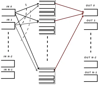
Figure 2.6: LB switch with single-stage buffering
complex switches with implemented feedback exchange links and which, correspondingly, require extra computation and communication overheads for proper functioning.
2.2.1 The architecture, assumptions and open issues
The basic single-stage buffering LB switch is shown in Figure 2.6 and consists of sets of buffers that are positioned in between of two identical crossbar switches [17, 40]. Each crossbar operates through similar predefined interconnection pattern in time according to the following rule:
j = (i+t) mod N, (2.1)
where N is the number of ports in the switch, i is an input(intermediate input at the central stage) number which is interconnected with intermediate input at the central stage (output). Time inside the switch is slotted and each stage assumed to be synchronized with other stages. The transmission of a packet (or a cell) between the stages could be done only in the boundaries of a time slot, i.e., only one packet during each time slot can arrive or depart. Each buffer in the central stage is organized as a set of N queues in a way that there is one queue (VOQ) associated with each output.
The operating idea behind the N-by-N switch size with a single-stage buffering ar-chitecture [17] is to load-balance packets from the inputs along the VOQs of the central buffering stage. Then, the packets are sent to the destination output ports. Arriving packets are switched instantly and there are no buffers inside the crossbars [17, 18].
The main purpose of this section is to highlight the initial LB switch features and to provide the proper background knowledge for the comparative analysis in this chapter further on.
idealized and several studies were built upon.
With this thesis, we will be calling packets of the same size as cells and, we assume them to be immediate multipliers of the variable size packets. For LB switch support of variable size packets the multi-stage buffering scheme can be used. Usually, input stage buffers are constructed in the similar manner like the central stage VOQs, in order the Head-of-Line blocking to be avoided [18, 40]. Another significant statement is relevant to line card synchronization. For each line card the common slotted time is used. Indeed, this assumption implies that the only one cell can arrive and depart switch during the time slot. Finally, each line card is able to support strictly equal rate flows. As one of the major assumptions to permit achievement of high throughput [39] for the initial single/multi-stage LB switch is traffic admissibility. Precise definition of this traffic type can be found in the section regarding input traffic matrixes.
The listed above fundamental assumptions can be found in each further work regarding LB switching. Definitely, recent schemes can use some specific assumptions due to their complexity (like symmetric interconnection pattern for crossbars); if there any of them will be found, they will be mentioned in the corresponding part.
Promises. Taking into consideration publications [16, 17, 39, 40] the LB switch is promised to be highly scalable (due to low scheduling complexity), and have 100% through-put for a broad class of arrival traffic like stationary, stochastic and weakly mixing inthrough-put sequences [38,53]. Absence of centralize control in initial schemes greatly reducing overall communication and computational overheads while providing cells arrival in their original order [39, 40]. It’s important to note that high throughput guarantees could be granted only in the case of infinite central stage buffers [18, 39] and assumptions of traffic admis-sibility. Further on, the degradation of throughput for the LB system with finite buffers will be examined in [65]. Initial LB scheme also assures to give a low average delay for the heavy traffic load under uniform, bursty and hotspot traffic [17, 39, 40]. Support of priority schemes and multicasting with fan-out splitting are realistic to implement in LB switch [39, 40]. Due to low hardware complexity, practical construction of the LB switch while using electronic components [40] (buffers and crossbars) is feasible [1, 32].
Recent modifications [15, 46, 57, 75] of the LB switch introduce additional overheads and make architectures more complex. However, the promises given to these architectures under highlighted conditions are equivalent (high scalability, low delay under various traffic matrices, high throughput). In following we would like to study the fulfillment of the guaranties when the size of the switch is considerably large (103 -104 ports).
ones.
Open issues
Cells mis-sequencing in the output. The first problem defined by early papers of C. S. Chang, N. McKeown and I. Keslassy is an issue of cells mis-sequencing experienced at output stage of the switch. A set of solutions were proposed. Conditionally, we distin-guish two different approaches to overcome the problem. The first set of algorithms are competing against cell mis-sequencing in the input and central stages. These algorithms use a special interconnection scheme to gain some feedback information about the cells in the input. Among the examples we highlight: the Padded Frames [34] algorithm used for initial scheme, the Mailbox Switch [15], the Concurrent Matching Switch [46] ,the frame-aggregated concurrent matching switch [47], the Contention and Reservation Switch [75], the two-stage switch with novel feedback mechanism [73], and the three-stage switch [74]. The second approach introduces algorithms using so called re-sequencing buffers in the output stage. As a rule, these operational algorithms are much simpler, however, hardware implantations require large buffering structures. The latter archi-tectures and algorithms are the Uniform Frame Spreading [39], First Ordered Frames First [40], and the Byte-Focal Switch [57].
Scalability. The initial architecture (see Figure 2.6) was promised to be scalable. Indeed, the system is not operating well mainly due to mis-sequencing problem [39, 40]. The proposed solutions as a rule promote some modifications of the system hardware or operational algorithms, bringing in extra communication and computation overhead and making system not scalable any more (like [46, 57, 75]). Being focused on the scalability issue as the main one, the next section will represent a comparative study between these novel architectures.
characterize the LB systems with variable size packets at least three parameters should be defined (for characterization of geometrically distributed packet length and inter arrival periods). According to the analysis performed in Section 5.1, the initial set of parameters of traffic patterns has a high influence on the overall performance of the system.
Throughput. In fact the throughput of the system is not always stable, and depends on the admissibility of incoming traffic. Mathematical analysis of the throughput and average delay in [17,40] presents practical interest for the future study. I. Keslassy in [31] had introduced the mathematical description of the interconnection capacity (and cor-respondigly the maximum possible throughput that interconnection can provide) related to the LB switch. The method allows the LB switch to be compared with ring, torus and hypercube interconnects. As a final result, it was proven in [31, 39] that for a given interconnection capacity, the load-balancing mesh has the maximum throughput.
Variable size packets support. Due to large variety of online applications, real Internet traffic use variable size packets. Since all the previous research is focused on the analysis of the LB switching architectures with fixed size data cells, the question of variable size packets support remains open. In the following sections we will consider this issue as one of the main focusing points for the future research.
Multicast and broadcasting of fixed and variable size packets. The amount of streaming Internet resources (like IPTV) has significantly increased recently. Tradi-tionally these resources were using multicast and broadcasting strategies to perform data distribution. In this context the support of multicast policy inside a network switch (like for instance in [12]) goes as the important requirement. The authors of [16, 29] argue that LB switch can multicast cells with fan-out splitting for first-come-first-served policy. By definition [29], ”the fan-out splitting implies transmitting cells to destination one at a time slot”. The proof is made for ATM switches which operating in the manner similar to cell-based LB switch.
The question of broadcasting and multicasting is still an open issue for the initial Birkhof-von Neumann switch [18, 40] as well as for Mailbox switch [15] and other resent architectures [46, 57, 75] using Round-Robin crossbars configuration principles described above.
size of the switch when the number of multicast flows O(logN) or smaller. Finding an appropriate scheduler for a given set of flows is NP-hard in general and depends on the amount of unicast and multicasting in the system.
Fault tolerance of the system and ways of practical realization. As it was shown in [31, 39, 40], the initial LB switch architecture is able to recover from the system failure in case of linecard missing during a time period of 50 ms. In order to redistribute the arriving traffic with equal rate at each link, some reconfiguration algorithms and two implementation designs (all-optical and hybrid optical-electronic architectures) were proposed by I. Keslassy et. al. in [39,40]. For scalability purposes, the authors of [1,32,39] propose subdivision of the LB switch architecture into groups (so calledhierarchical mesh implementation and mesh decomposition as a sum of matches). Each of newly proposed designs can be implemented using just optical components. However the designers can face the problem of extremely high complexity of all-optical buffers (in particular FIFO queues) [13, 14]. Practically these structures can be emulated with a set of simple 2×2 switches and fiber delay lines. For instance, in [14] the three-stage realization of optical FIFO queues was presented. It is noted that the queue with buffer of 2n−1 cells was realized by using 2n 2×2 switches with the total fiber length of 3·2n−1−2 meters, which is considered to be a complex solution for a single FIFO queue of size 2n−1.
2.3
LB Switch Designs Preventing Cells Mis-Sequencing
The amount of mis-sequencing occurred during traversing the switch has an important impact on the overall performance of the network [66]. This problem is also crucial for the LB switch operating with variable length packets, where unbounded amount of mis-sequencing can lead to throughput degradation and enlargement of average switch traversing delay. In general, cells will be mis-positioned if the related central stage VOQs are occupied at different levels.
First we introduce schemes where algorithms for preventing mis-sequencing at input and central buffer stages are implemented. Several algorithms use specific crossbar inter-connection scheme to provide some feedback information about the outstanding cells in the central stage. Such methods can have extra communication and computation over-head but usually provide good delay characteristics similar to the original LB switch. Finally, we conclude the discussion about the schemes which use re-sequencing buffers at the output buffer stage.
2.3.1 Uniform frame spreading
additional cell reordering hardware and is not using any re-sequencing buffers in the output. The main idea of the UFS is to spread equally cells to all the VOQs destined to the same output. The input stage of the switch composed from the N FIFO queues, so the buffering structure is the same as in the central stage. Arriving cells destined to the appropriate output are kept in the input buffers until there are N of them in the queue (make up afull frame). During the nextN time slots the cells are spread along the corresponding VOQs of the central stage. It is assumed that initially there are no cells in the central stage and the cells become head-of-line of the relevant VOQ. This policy is applied for each input, so finally each cell departs the switch in order.
In spite of the fact that this distributed algorithm shows good results for a heavy traffic load, it is evident that the throughput can be low in case of light load. If a frame is not full it is necessary to wait undefined time to complete a frame, this situation may cause starvation.
2.3.2 Padded frame algorithms
The the Padded Frames (PF)and improved PF (PF+)algorithms proposed in [34] are considered as a generalization of the previous scheme. In similar manner the multi-stage buffering scheme is used.
In the new algorithm the absence of full frame will not lead to starvation. The al-gorithm selects the largest nonempty queue with say F < N cells and inserts N −F
empty cells to obtain a padded frame. Right after, frames are spread between the central stage buffers as in the UFS scheme. After arrival to the output fake cells are immediately dropped. Definitely, this may create instability in the system during the light loads when the amount of padding is very high.
Analysis of traversing packet delay and throughput shows that UFS, PF as well as full ordered frames first (FOFF) algorithms are strongly dependent on incoming traffic pattern and the load of the switch. While considering admissible traffic [17, 39] with matrixes close to self-similar [44, 59], PF scheme shows the best delay characteristics, while the UFS scheme [39] has starvation problems under light loads and while small bursts are received. The modified versions of the original LB switch to prevent the cells out-of-order issue were proposed in [15, 46, 57, 75]. Following sections will explain the operating principles of these designs.
2.3.3 The mailbox switch
each other exactly once in every N time slots. The general assumptions for this design is similar to the one presented in Section 2.2.1. Buffers are called mailboxes, there are N
mailboxes each of it containsN bins with F cells (here ”cell” has meaning of a buffering unit) in it (each cell can store exactly one equal size packet). The switch uses a single FIFO queue for each input.
F I F O 1
N
1
N
C r o s s b a r C r o s s b a r
M a i l b o x
1 2 . . . F 1
N
C e l l
B i n
Figure 2.7: The Mailbox switching architecture [15]
The key idea of the mailbox switch is to use a set of symmetric connection patterns (Figure 2.8) to create a bidirectional link for transferring the information about the packet departure times using construction properties of the switch (each input and output is assumed to be implemented at the same line card). The information contains the value of virtual waiting time (VWT) Vi,j(t) for each traffic flow that is the departure time of
the last packet from input i to output j in the mailboxes. When a packet from i to j
becomes the head-of-line packet of a FIFO queue at time t, the mailbox switch locates the packet in the mailbox such that it will depart not earlier thant+Vi,j(t). Having this
timing information, the switch can schedule packets so that they depart in the order of their arrivals.
i
j
i
j i
j
Figure 2.8: Example of symmetric interconnection pattern [15]
1
N
1
N S - T D M s w i t c h
I - V O Q s V O Q s
S - T D M s w i t c h
Figure 2.9: The Contention and Reservation switch [75]
packet blocking will result in low throughput and large delay. In order to solve these problems the authors implemented search of empty cells with limited number of forward and backward tries [15].
2.3.4 The Contention and Reservation switch
In [75], a novel Contention and Reservation switch (CR switch) design was pro-posed to address the cell reordering problem (Figure 2.9). It is considered to be an improvement of the Mailbox switch (Figure 2.7) proposed in [75]. The basic assumptions about the packet size, synchronization and flow rate are similar to the initial scheme presented in (Section 2.2.1). The CR switch like the Mailbox switch uses symmetric in-terconnection pattern to provide feedback bidirectional links from central buffers to the connected input buffers. The idea behind this, is to use different operational modes for different input stage loading of the switch. The algorithm presents the combination of the good features of the UFS scheme under heavy load and Mailbox switch in the light load without throughput reduction.
2.3.5 The Concurrent Matching switch
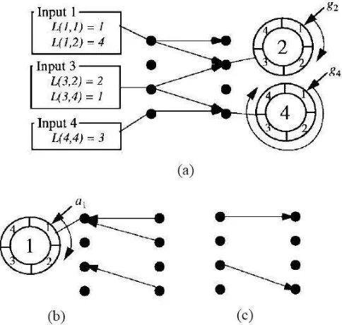
The Concurrent Matching switch (CMS) uses two identical stages of fixed opti-cal configuration meshes (Figure 2.10). The optiopti-cal mesh presents Space Division Mul-tiplexing (SDM) approach instead of Time Division MulMul-tiplexing (TDM) of crossbars. Input stage of the switch is implemented using VOQs structure. The intermediate inputs equipped with coordination slots and virtual counters (each line card maintains N2 vir-tual counters, one counter for each flow). The main assumptions are similar to the ones shown in the Section 2.2.1.
Incoming cells are buffered in input VOQs of corresponding line card. Instead of instant cell load-balancing among the second stage, first each input sends the request tokens cyclically to the central stage, so the counters in the central stage are updated immediately about the traffic state in the input. Right after each intermediate input is solving the matching problem (while using only local counters information). Based on the matching result, the grant tokens are sent to each input back and appropriate counters are decremented. Only after this step, the corresponding VOQs in the input are allowed to send cells to the intermediate inputs, where they are stored temporarily in the coordination slots. Finally, during the nextN time slots cells depart to the corresponding outputs of the switch.
V i r t u a l O u t p u t Q u e u e Zi , k
P a c k e t P a y l o a d
H e a d e r
F l o w S p l i t t e r
R e q u e s t t o k e n q u e u e s R
i , j
C o o r d i n a t i o n s l o t s R
j , k
V i r t u a l t o k e n c o u n t e r s
C i , k j
2.3.6 Re-sequencing in the multi-stage buffering scheme
In this section, we analyze the architectures that are overcoming cells mis-sequencing problem at the output stage. First we discuss the basic approach with re-sequencing outputs, showing difficulties related to hardware implementation. Similar to the UFS algorithm, examined in previous section, we will present a modified scheme, called first ordered frames first (FOFF), which bounds the amount of cells mis-sequencing, but still require output reordering. Finally, the novel Byte-Focal switch that is using virtual input queuing (VIQ) structure for output reordering will be presented.
In the original multi-stage buffering scheme [18] cells from the same flow in the input are spread in the round-robin mannerto the corresponding VOQs (Figure 2.11) and are served with the first come first served (FCFS) policy (same as FIFO). The advantage of it is a traffic mixing along the input VOQs with respect to their departure times. A jitter control mechanism is used to delay cells to some maximum predefined value at the first stage so that flows entering the second stage are simply equally time shifted flows of the original ones. A set of theorems presented in [18], with consideration of two types of scheduling policies (first come first served and earliest deadline first) demonstrate system implementation complexity comparable with FOFF re-sequencing algorithm, which is described next.
1
N S e c o n d s t a g e F C F S
F i r s t s t a g e F l o w
S p l i t t e r
J i t t e r C o n t r o l
q2
j , k
q1
i , j
A1
i , 1 , j
B1
i , 1 , j
A1
i , 1 B
2 j , k
C e n t r a l b u f f e r N
1
L o a d - b a l a n c i n g b u f f e r R e - s e q u e n c i n g a n d
o u t p u t b u f f e r
Figure 2.11: LB switch with multi-stage buffering [18]
The FOFF was described in [39, 40] and applied to the multi-stage buffering LB switch. The FOFF algorithm operates in the manner similar to the UFS but allows to sent a sequence of cells even if there are less than necessary to create a full frame. Every cycle of N time slots each input examines the availability of a full frame. Sending a full frame has a priority over the uncompleted ones. During the next N time slots cells of a frame are spread uniformly over the central stage [40]. If full frames are not available the algorithm checks other non-empty queues with number of cells K < N. During the next
1
N C r o s s b a r
V O Q 1 ( i , k )
C r o s s b a r V O Q 2 ( i , k )
V O Q 1 ( 1 , 1 )
V O Q 1 ( 1 , N )
V O Q 1 ( N , 1 )
V O Q 1 ( N , N )
V O Q 2 ( 1 , 1 ) i = 1
i = N
j = N j = 1
V O Q 2 ( N , N )
k = 1 R B V I Q ( i , j , k )
k = N V I Q ( 1 , 1 , 1 )
V I Q ( 1 , N , 1 )
V I Q ( N , N , N )
Figure 2.12: The Byte-Focal switch [57]
traffic load when the full frame cannot be created. But as it was shown in [39] the amount of mis-sequencing is always bounded. For that reason the output stage is equipped with output and re-sequencing buffers which remove remaining amount of mis-sequenced cells. Each output buffer usesN FIFO queues with size that is no less than N2+ 1 cells.
2.3.7 Byte-Focal switch
The novel Byte-Focal Switch [57] (Figure 2.12) is equipped with two sets of VOQs in input and central stage (V OQ1 andV OQ2 correspondingly) andVIQs, which are used as re-sequencing buffers at the output. At each output there areN sets of VIQs, each set is related to some input porti. Within each VIQ set, there are N logical queues with each queue corresponding to a second stage j as well. Cells from inputi designed to output k
via second stage inputj are finally stored inV IQ(i, j, k), and its obvious that the cells in the same V IQ(i, j, k) are in order. The advantage of using VIQs is that the complexity of finding and serving cells in sequence isO(1).
Since eachV OQ1(i) is made of a set of V OQ1(i, k)sthe way in which oneV OQ1(i, k) should be chosen among the others have to be considered (only one queue can transmit to the central stage during N time slots). Indeed, three solutions were proposed, among themthe round-robin scheme (A),the longest queue first, (B) and the dynamic threshold scheme (C) were shown in [57]. First solution gives fairness (A) for every queue but behave poorly with non-uniform traffic. Another two are able to handle problematic traffic but have extra computation overhead (B). The (C) scheme provides optimized delay performance results for a wide range of traffic patterns, packet lengths and packet length distributions.
and overheads. As mentioned, the solutions with re-sequencing in the input stage are considered to have extra computational and communication overheads. On the other hand, the architectures solving out-of-sequence issue with output re-sequencing can also have high hardware complexity like in [18] or due to the fact that large amount of buffers is used [57]. In the following section we will analyze all possible overheads and algorithmic complexity of all mentioned above schemes.
2.4
Evaluation of the System’s Scalability in Space and Time
The initial LB switch described in [17] has a simple control and considered to be a highly scalable solution. However, as a switching fabric it is proposed to use bufferless crossbar switches, which are known to be poorly scalable when the switch size is large(103 ports). Contrarily, LB switch has a predefined round-robin interconnection pattern and do not require all possible states interconnections from a crossbar. This fact gives a possibility to replace crossbars with less complex Clos [19], Benes [51] and Banyan network-based schemes in [15, 17, 64] together with Space Division Multiplexing switches (fixed mesh) in [35, 39, 42]. These ideas are introduced in Section 2.4.1.
In some newly proposed switches [15], [75], [46], [73] feedback links are used to prop-agate additional information about the state of the other stages of the switch. Take, for example, the Mailbox switch where information about cells departure times is transmitted from central stage to the input. As a rule, some extended controllers are used to process specific information. In fact, the computational and communication overhead can be a bottleneck for the large switches. In the section 2.4.2 we will derive some conclusions on the ability of such designs to scale up.
2.4.1 Scalability limitations regarding the basic scheme
requires only N matrixes for each input to be realized. Practically, the composition of (Nlog2N)/2 2 x 2 switches is required to buildN ×N Banyan network.
The way to implement large N x N symmetric (the condition (i+j) mod N = (t+ 1)mod N should hold true) TDM switches with number of ports N = 2k was presented
together with the Mailbox switch in [15]. EachN xN TDM switchN =pq consist of two stages. The first stage consists ofp q x q symmetric TDM switches and the second stage consists of q p x p symmetric TDM switches. The stages are connected by the perfect shuffle, i.e. the l−th output of the k−th switch at the first stage is connected to the
k−th input of the l−th switch at the second stage.
As an alternative to the TDM switches, authors of [30, 31] proposed to use a fixed optical mesh(sometimes with WDM). The crossbars are replaced with the two optical meshes where one mesh running twice as fast. It is assumed that the inputs, the output and the central buffers are implemented on the same line card. The packet traversing rate is equal to 2R/N [39]. Each input is simply multiplex (not only in time but also in space) incoming packets among the central buffers, in the similar manner like packets are demultiplexed at the output. For LB switch multiplexing and demultiplexing should be also uniform. The throughput characteristics of the LB switch while using different optical mesh interconnections are presented in [31].
2.4.2 Scalability of recent architectures, computation and communication overhead
The Mailbox switch
The Mailbox switchwas depicted in Figure 2.7. The main goal of the Mailbox switch is to service packets in order through the switch. In the following architecture the scalability can be limited by the following factors: (1) crossbars switches and (2) computational and communication overhead. As mentioned, the Mailbox switch uses symmetric interconnec-tion pattern in order to create a bidirecinterconnec-tional communicainterconnec-tion link between an input and output stage, since they usually implemented in the same line card. To service packets in order, the packet departure time is fed back to the input stage, so the next packet will have all the required information about the transmission time. Authors in [15] propose several strategies, which in fact have different computation and communication overhears. In the following we examine in the detail possible overhead which can have a switch with large number of ports (103-104) and different packet size.
Generic architecture. Generic Mailbox switch, while using symmetric interconnec-tion, feed back a VWT to the packet in the input stage. The virtual waiting time Vij(t)
central stage bins it is possible to calculate in advance packet service and departure times (since all the crossbar interconnections are deterministic and periodic). The operating phase for the Generic architecture is the following:
1 step Retrieve mails: According to current interconnection between output j and mail-box h(j, t), the transmission of the packet from corresponding bin j (of mailbox) is happening. The waiting time for the packets placed in some other mailboxes can be easily determined as soon as the placement is done.
2 step Send mails: The transmission of the packet from input i to mailbox h(i, t) and bin j (according to crossbar interconnection) occurs. The packet is not allowed to depart before t+Vij(t).
3 step Update VWTs: The flows that do not send mail during time slot t update their VWT for time slot t+ 1.
Depending on the arriving traffic if the arriving packet can find an empty cell in the mailbox (say at the position f, which is less than F-length of the buffer), than transmission is successful, otherwise packet will be blocked at the HOL position of the input stage. More precisely, for each placement of the packet inside the central stage bin, the interconnected input will receive log2(F N) bits of information. Moreover, at each input port i, the information aboutVij(t) for all outputs is kept.
Lets assume that the switch size is 103 ports and the equal size packets are L = 128 bits(16 bytes). As it is usually assumed that central stage buffer length should be at least slightly larger than the switch size, we will obtain that ǫ = log2(NF)/L = log2(103103)/100 = 20/128 = 0.156 or 15.6% of the overhead. Please note that the amount of the overhead will increase in case if buffers are larger than the value considered. The same one can apply to larger packet size (say 1500 B). Communication overhead can influence on the performance characteristics of the Mailbox switch also if feedback links are experiencing unexpected delays in information transmission. On the other hand, during this scenario Generic Mailbox switch doesn’t have any large computation overhead, since it needs only increment/update waiting time counters (up to N for each input) for the next packet transmission.
The Mailbox switch with cell indexes. In spite of the Generic approach which is not defining the value of the position f where the cell will be placed inside the bin, in approach with cell indexes switch tries to minimize value fij(t) such that the packet
will not depart earlier than t +Vij(t). In general fij(t) is called cell index of VWT
Vij(t). In addition tofij(t) a new counter gij(t) for flow (i, j) is introduced. In this case
all the information of fij(t) and gij(t) is kept in the input for all possible outputs(from
2 step Send mails: Packet from inputiis transmitted to specified mailbox together with
fij(t). Then the packet is placed to binj and to some cell in the rangemax(fij(t),1).
If placement was successful than the index is assigned (say f), otherwise f = 0 and error message transmitted to i output;
3 step Update VWTs: If the transmission was successful, than fij(t+ 1) can be easily
defined by f at time slot t and gij(t) is reset to N. Otherwise if transmission is not
successful than again fij(t+ 1) =fij(t) and gij(t+ 1) =gij(t)−1.
Lets make small investigations on the overheads of presented model. Presented ap-proach has smaller amount of communication overhead due to transmission of only cell indexes. Taking into account previous example (N = 103 ports, F = 103 cells and packet
L = 128 bits) we obtain ǫ = log2(F)/L = log2(103)/128 = 10/128 = 0.0781 or twice less than in previous example. On the other hand each input now have to keep track and update (every time slot) bothfij(t) andgij(t) counters (in general up to 2N values during
a time slot). Since that the computation overhead of the system will be doubled.
The Mailbox switch with a limited number of forward tries. In the previous approach it can happen that in order to find an empty cell for a packet from a flow several tries might be done. For each unsuccessful try the VWT will increase by N time slots (like collision). Accordingly if the collisions are happening quite often, packets will not occupy available capacity of mailboxes. In order to avoid that authors in [15] put a limit on additional waiting time δ in case of collision such that fij(t)∈min(fij(t) +δ, F). Please
note that δ is a maximum increment of the index of cell waiting time. For the presented case the overheads are similar like in previous approach. The implementation improves systems’ throughput and delay.
Mailbox switch with a limited number of forward and backward tries. The problem of finding empty cell can be solved by mean of backward tries(it is bounded by
Nδb time slots), e.g. if free cell position is looked not only in the forward but also in
the backward direction. The new constraint for cell indexes fij(t) is in the interval from
max(fij(t)−δb,1) to min(fij(t) +δ, F).
It is easy to see that the amount of communication and computation overheads do not change, since only the interval of fij(t) was changed. Based on [15], the last two
The Contention and Reservation switch
Next we examine the Contention and Reservation switch introduced in [75] that merge the advantages both of the Mailbox switch and the Uniform Frame Spreading. The CR switch is operating in two modes: the contention mode and the reservation mode.
The operating switch needs to send one bit of data to inform whether the transmission of contention packet was successful or not. The feedback information is sent from the central stage buffers to the inputs. The communication overhead of the system during a time slot is just one bit of information and not depend on the switch size. Taking into account previous example (N = 103 ports, F = 103 and packet size is L = 128 bits) we obtain ǫ= 1/L= 1/128 = 0.00781 or 0.781% of overhead. Communication overhead can be significant if transmission delays between the stages are large.
<
![Figure 2.10: The Concurrent Matching switch [46]](https://thumb-us.123doks.com/thumbv2/123dok_us/853983.2079747/41.612.201.429.431.673/figure-the-concurrent-matching-switch.webp)
![Figure 2.12: The Byte-Focal switch [57]](https://thumb-us.123doks.com/thumbv2/123dok_us/853983.2079747/43.612.132.499.74.274/figure-the-byte-focal-switch.webp)
![Figure 2.13: The Frame-Aggregated CM switching architecture [47]](https://thumb-us.123doks.com/thumbv2/123dok_us/853983.2079747/50.612.196.365.208.390/figure-the-frame-aggregated-cm-switching-architecture.webp)